Guidewire Antennas for MRI-Guided Vascular Interventions
Mark E. Ladd, Peter Erhart, Susanne C. Göhde, Jörg F. Debatin, Graeme C. McKinnon
Departement Medizinische Radiologie, MR-Zentrum, Universitätsspital Zürich, CH-8091 Zürich, Schweiz
Introduction
Becauseofitsexcellentsofttissue contrast, ability to image in an arbitrary plane, and lack of ionizing radiation, great interest has been shown in using MRI to guide vascular interventions. Before a catheter can be safely introduced, a guidewire needs to be placed. Unlike conventional X-ray fluoroscopy, however, the ability to quickly and reliably visualize thin objects like guidewires has proven to be difficult. One solution is the use of active receive antennas built into the guidewire tip (1).
A number of antenna configurations are possible, including simple loop, solenoid, center retum, etc. (2). In order to understand and optimize these antennas, a series of theoretical simulations and experimental measurements were performed. In addition, the effect of adding a passive signal source (e.g. water) 'internal to the guidewire was explored.
Methods
Biot-Savart modelling was used to calculate the magnetic field pattems of the following antenna types: single loop, crossed loop, 4-wire center return, and solenoid. From these field patterns, sagittal-like images with a slice thickness of 5 mm were simulated with the coils both parallel and perpendicular to the main magnetic field, B0, of the MR imager. The in-plane
resolution was 0.1 mm in both directions.
Prototype guidewires were constructed by Schneider Europe AG. Each guidewire was constructed with a coil approximately 60 mm long and 0.6 mm in diameter. After enclosing the guidewire in a Teflon sheath, the final outside diameter was 0.75 mm, small enough to fit into the lumen of a 5 French catheter.
Water doped with Gd-DTPA (Schering AG) was injected into the prototype guidewires äs an intemal, passive signal source.
Results
Fig. l shows a simulated image of a single loop guidewire with no signal source in the interior of the coil. The coil is parallel to B0. Fig. 2 shows the same
coil with an internal signal source.
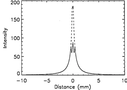
Fig. 3 shows the profiles of image intensity from left to right for both cases. The profiles show that the internal source not only increases the available signal, it also narrows the apparent line width of the guidewire.
Fig. L Simulated image of single loop guidewire
without internal signal source.
aamiafflB^pffifflflffif IBI^IBBBBi
Fig. 2. Simulated image of single loop guidewire
with internal signal source.
0
-10 - 5 0 5
Distance (mm) 10
Fig. 3. Profiles of image intensity across the above
images. Solid line = without intemal source, dashed
line = with internal source.
This is also desirable, since it provides better localization. If the internal source is a substance with a short relaxation time TI} then a third benefit is the
ability to scan with fast imaging sequences (short TR's).
Fig. 4 shows a magnified, experimental image of the [2] G.G. Hurst, et al.; Magn Reson. Med. 24, 343-357 single loop prototype taken with the coil parallel to B0. (1992)
Water/Gd-DTTPA was injected into the intenor of the coil. The 6 cm tip of the guidewire i s depicted quite well. Sequence parameters were TR 300 ms, TE 2.3 ms (fractional), flip angle 60°, FOV 20 cm, matrix 512x512, l NEX.
Fig. 4. Experimental image of single loop prototype guidewire parallel to BQ.
Conclusion
The selection of the appropriate guidewire coil depends on a combination of factors. The single loop, crossed loop, and center retum all perform better parallel to B0. The solenoid performs best orthogonal to B0.
Thus, depending on where the intervenüon is to be performed, one might choose one over the other.
A second factor is ease of mechanical construction. The single loop and solenoid are both easy to constmct. The crossed loop and center retum are more difficult because four long wires need to be kept straight and equidistant. This proved problematic in the prototypes.
The most deciding factor is the addition of a passive Signal source in the highly sensitive area near the center of the coil. This increases the SNR, reduces the line with, and with Gd-DTPA induced Tl shortening, permits the use of fast imaging.
Acknowledgments
This work was funded by General Electrical Medical Systems, Milwaukee, Wisconsin, and the Swiss National Science Foundation, Grant Nr. 32-43284.95.
References
[1] M.E. Ladd, et al.; "Proc., ISMRM, Fourth Meeting", 1736 (1996)
![Fig. 4 shows a magnified, experimental image of the [2] G.G. Hurst, et al.; Magn Reson](https://thumb-eu.123doks.com/thumbv2/123doknet/14895641.651377/2.1258.78.590.302.805/fig-shows-magnified-experimental-image-hurst-magn-reson.webp)