HAL Id: hal-02498444
https://hal.archives-ouvertes.fr/hal-02498444
Submitted on 8 Dec 2020
HAL is a multi-disciplinary open access
archive for the deposit and dissemination of
sci-entific research documents, whether they are
pub-lished or not. The documents may come from
teaching and research institutions in France or
abroad, or from public or private research centers.
L’archive ouverte pluridisciplinaire HAL, est
destinée au dépôt et à la diffusion de documents
scientifiques de niveau recherche, publiés ou non,
émanant des établissements d’enseignement et de
recherche français ou étrangers, des laboratoires
publics ou privés.
Oscar Caravaca Mora, Philippe Zanne, Lucile Zorn, Florent Nageotte, Natalia
Zulina, Sara Gravelyn, Paul Montgomery, Michel de Mathelin, Bernard
Dallemagne, Michalina Gora
To cite this version:
Oscar Caravaca Mora, Philippe Zanne, Lucile Zorn, Florent Nageotte, Natalia Zulina, et al..
Steer-able OCT catheter for real-time assistance during teleoperated endoscopic treatment of colorectal
can-cer. Biomedical optics express, Optical Society of America - OSA Publishing, 2020, 11 (3), pp.1231.
�10.1364/BOE.381357�. �hal-02498444�
Steerable OCT catheter for real-time assistance
during teleoperated endoscopic treatment of
colorectal cancer
O
SCARC
ARAVACAM
ORA,
1,3P
HILIPPEZ
ANNE,
1L
UCILEZ
ORN,
1F
LORENTN
AGEOTTE,
1N
ATALIAZ
ULINA,
1S
ARAG
RAVELYN,
1P
AULM
ONTGOMERY,
1M
ICHEL DEM
ATHELIN,
1B
ERNARDD
ALLEMAGNE,
2AND
M
ICHALINAJ. G
ORA1,41ICube Laboratory, CNRS, Strasbourg University, 4, rue Kirschleger - 67085 Strasbourg Cedex, France 2IRCAD - Hôpitaux Universitaires - 1, place de l’Hôpital - 67091 Strasbourg Cedex, France
3caravacamora@unistra.fr 4gora@unistra.fr
Abstract: When detected early, colorectal cancer can be treated with minimally invasive flexible endoscopy. However, since only specialized experts can delineate margins and perform endoscopic resections of lesions, patients still often undergo colon resections. To better assist in the performance of surgical tasks, a robotized flexible interventional endoscope was previously developed, having two additional side channels for surgical instrument. We propose to enhance the imaging capabilities of this device by combining it with optical coherence tomography (OCT). For this purpose, we have developed a new steerable OCT instrument with an outer diameter of 3.5 mm. The steerable instrument is terminated with a 2 cm long transparent sheath to allow three-dimensional OCT imaging using a side-focusing optical probe with two external scanning actuators. The instrument is connected to an OCT imaging system built around the OCT Axsun engine, with a 1310 nm center wavelength swept source laser and 100 kHz A-line rate. Once inserted in one of the side channels of the robotized endoscope, bending, rotation and translation of the steerable OCT instrument can be controlled by a physician using a joystick. Ex vivo and in vivo tests show that the novel, steerable and teleoperated OCT device enhances dexterity, allowing for inspection of the surgical field without the need for changing the position of the main endoscope.
© 2020 Optical Society of America under the terms of theOSA Open Access Publishing Agreement
1. Introduction
Colorectal cancer is the third most common cancer in the world in terms of incidence, and takes the second place in mortality worldwide [1]. The most common treatment approach for colorectal cancer is based on resection of the diseased section of the organ during open or laparoscopic surgery [2]. However, early detection allows for minimally invasive treatment options. In this case, early stage cancerous lesions are removed using flexible endoscopy procedures, including endoscopic mucosal resection (EMR) and endoscopic submucosal dissection (ESD) [3,4]. Unfortunately, these minimally invasive endoscopic treatment options are not commonly performed due to their complicated nature, requiring highly experienced clinicians to localize lesions while simultaneously manipulating the endoscope and other surgical tools [5]. An example of a solution addressing these challenges is the development of flexible interventional endoscopes with two insertable therapeutic instruments [6].
Similar challenges existing in laparoscopic procedures have been addressed by the introduction of robotized and teleoperated rigid endoscopic systems [7]. These systems are currently a standard of care in the treatment of prostate cancer and are at an early stage of adoption for colorectal cancer [2,8]. Compared to their rigid counterparts, robotization of flexible endoscopes
#381357 https://doi.org/10.1364/BOE.381357 Journal © 2020 Received 4 Nov 2019; revised 22 Dec 2019; accepted 27 Dec 2019; published 3 Feb 2020
carries additional challenges related to precise prediction of the endoscope’s positions and its manipulation in the confined space of the colon [9]. Such endoscopes have previously been fully robotized to allow a single operator to independently telemanipulate the flexible endoscope and two insertable therapeutic instruments with a joint control unit [10]. However, robotic-assisted flexible endoscopes are subject to the same diagnostic difficulty as standard endoscopy, which relies on the investigation of superficial mucosa with white-light followed by microscopic imaging of collected biopsy samples to confirm tissue status. Small tissue biopsy may easily miss early cancerous lesions and, in addition, may cause submucosal fibrosis that will negatively impact minimally invasive procedures such as ESD [11]. It is thus important to provide physicians with a minimally invasive tool for inspection of lesions during treatment.
Endoscopic OCT is a promising candidate to provide real-time information about lesion margins [12]. Preliminary results have demonstrated that OCT has the potential to differentiate healthy from diseased tissue in the digestive system [13], and a recent publication demonstrate the use of OCT and machine learning methodologies for accurate diagnosing of colonic tumors [14]. The ability of OCT to visualize tissue architecture including the submucosa is important to potentially stage cancer, identify lesion margins and guiding needle injection of saline during interventional endoscopic procedures such as EMR and ESD. However, similarly to other microscopic technologies like confocal endomicroscopy or endocytoscopy [15,16], it suffers from a small field of view per single measurement and scanning needs to be implemented to extend the imaging area [17]. Most of the current developments are focused on opto-mechanical solutions that target scanning of the distal part of the esophagus for the management of Barrett’s esophagus [18,19]. The most advanced solution based on a rigid balloon centering an OCT catheter is not optimal for the delineation of lesions during minimally invasive treatment. In order to inspect a larger field of view, a probe with three-dimensional scanning is often positioned in various locations of the organ using motion of the endoscope tip, which is not recommended during minimally invasive procedures because the endoscope is used to deliver surgical tools. In addition, OCT probes are usually inserted into the digestive system using a working channel of the endoscope that is also used for insertion of treatment instruments; as such it is impossible to perform intra-therapy analysis of the tissue. The majority of work related to monitoring of treatment using endoscopic OCT, so far, has thus been performed in the pre- or post-therapy modes [20–25]. In the digestive system, OCT has been used to assess the efficacy of esophageal treatment with radio frequency ablation [26]. The monitoring of radio frequency ablation treatment with endoscopic OCT has also been investigated for the management of cardiac arrhythmias using an OCT probe inserted into the steerable introducer through a percutaneous access point [27]. To enable real-time and intra-operative monitoring, multimodal catheters combining OCT with radio frequency ablation for the treatment of Barret’s esophagus [26,28] and cardiac arrhythmias [29,30] have been proposed.
Here, we present a novel steerable endoscopic OCT system for the inspection of a surgical field intraoperatively. The OCT catheter was designed to be inserted into a side instrument channel and has been fully robotized for compatibility with teleoperation of the robotized interventional flexible endoscope. Detailed analysis of the mechanical performance of the probe has been performed in the presence of different angles of bending of the catheter to minimize artefacts related to non-uniform rotational distortions [31–34]. Finally, we validated performance of the OCT enhanced robotized flexible endoscope in ex vivo phantom and in vivo swine experiments. 2. Methods
2.1. Steerable OCT catheter
The novel steerable OCT catheter is comprised of an internal optical fiber probe sheathed with a torque coil of 0.9 mm outer diameter and enclosed inside a transparent inner sheath (Pebax) of 1.62 mm outer diameter. To enable flexion of the catheter the inner sheath is inserted into a
steerable shaft with an outer diameter of 3.5 mm. The distal 20 mm of the transparent sheath is exposed to enable OCT imaging. The bending segment of the shaft is composed of cylindrical vertebrae that starts at 33.5 mm from the tip of the catheter and has a length of 27 mm. The bending motion within the range from -60° to 90° is actuated by two antagonist cables enclosed in the shaft (Fig.1). The catheter side-focuses the near infrared light to 1.3 mm outside the plastic sheath to a spot of 40 µm in size with an optical power of 9.6 mW. The proximal end of the steerable shaft is terminated with a motorized flexion actuator enclosed in a driver (FA, Fig.1) that pulls on the cables in an antagonist manner to change the bending angle. The optical probe and the sheath are threaded through the center of the driver towards the volumetric scanning actuator (RJ, Fig.1) which is composed of a rotary joint (MJXA-SAP-131-28-020-FA, Princetel, New Jersey) and a linear translation stage (SHT-08-C2BF1-A0F0B-AV0A0AA, igus GmbH).
Fig. 1. Schematic drawing and picture of the OCT steerable catheter connected to the OCT system (OCT) via volumetric scanning actuator (RJ) together with detailed schemes of instrument driver module (IM) with flexion actuator (FA) and distal bendable section of the catheter.
The scanning actuator is connected to an external custom OCT imaging console built around an Axsun OCT engine with a swept source laser centered around 1310 nm. The Axsun system is connected to a custom fiber-based Mach-Zehnder interferometer [35] with fiber polarization diversity balanced detection (PDD) connected to two balanced photodiodes in the Axsun system [36]. The use of the PDD allows for compensation of the intensity variations of interference signal caused by the rotation, bending and continuous motion of the optical fiber probe [37]. The system provides sensitivity of 97 dB, tissue penetration of ∼1 mm, an axial resolution of 5.6 µm (in air), and a repetition rate of 100 kHz.
2.2. OCT enhanced robotized interventional flexible endoscope
The robotized interventional flexible endoscope is based on a manual Anubiscope (Karl Storz) [6]. To improve maneuverability and triangulation during minimally invasive endoscopic procedures this endoscope has two additional side-channels dedicated to treatment instruments as shown in Fig.2[38]. In addition, the Anubiscope platform has a regular working channel and a fluid channel. The manual Anubiscope platform enables triangulation of the two instruments with the camera at the center. Robotization was added to provide telemanipulation and single user operation to control the motions of the main endoscope and the surgical instruments [38].
Fig. 2. (A) Schematic drawing of the robotized flexible interventional endoscope with the steerable OCT
catheter attached to a slave cart that is connected to user controllers for teleoperation of the device: instrument actuators (IM1, IM2), pullback scanning actuation (RJ), OCT system (OCT), endoscope processor (Endo P), endoscope light source (Endo LS). (B) Front view of the distal end of the robotized flexible interventional endoscope with steerable OCT catheter.
The OCT imaging system and the catheter scanning actuator are integrated into the robotized flexible endoscope cart (Fig. 2). The OCT display screen is placed next to the endoscopy display and the user can use a mouse and a keyboard to setup the OCT acquisition parameters. The steerable OCT catheter can be inserted into one of the instrument channels of the robotized endoscope (Fig. 2(B)). Once in the channel, the whole catheter together with its flexion driver can be rotated and translated by the motors located at the proximal end to add two degrees of freedom (Fig. 2(A)). The navigation and positioning of the OCT probe can then be teleoperated using one of the two master controllers in a similar manner to any other surgical tool integrated with the robotic system (Fig. 3).
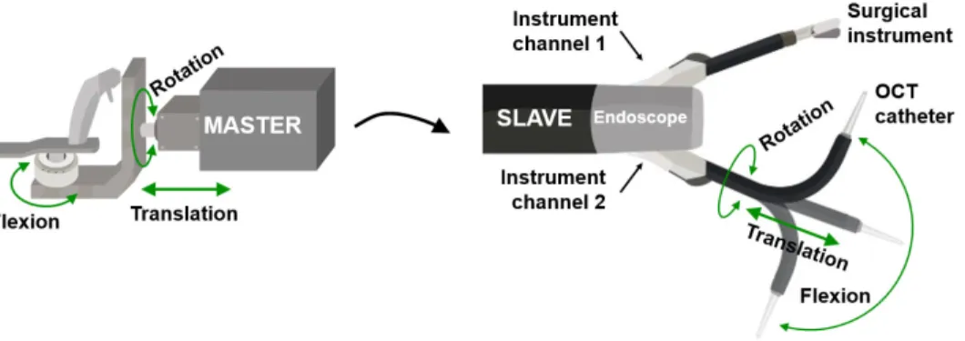
Fig. 3. Schematic drawing of transmission of motions from master controller (on the left) in teleoperation
mode to the distal tip of the steerable OCT catheter that enables its rotation, translation and flexion (slave unit on the right).
2.3 Non-uniform rotational distortion measurement
In a first step we tested the dependence of the non-uniform rotational distortion (NURD) with the bending angle of the steerable OCT shaft as well as the rotational speed of the OCT probe. To assess the NURD value we used a rectangular tube with known dimensions to measure four angles formed by the diagonals traced from the center of the sheath to each corner of the interior section as previously published (Fig. 4) [39]. Fig. 4(A) shows the dimensions and angles corresponding to the theoretical geometry and the actual 3D printed rectangular tube. ImageJ
Fig. 2. (A) Schematic drawing of the robotized flexible interventional endoscope with the steerable OCT catheter attached to a slave cart that is connected to user controllers for teleoperation of the device: instrument actuators (IM1, IM2), pullback scanning actuation (RJ), OCT system (OCT), endoscope processor (Endo P), endoscope light source (Endo LS). (B) Front view of the distal end of the robotized flexible interventional endoscope with steerable OCT catheter.
The OCT imaging system and the catheter scanning actuator are integrated into the robotized flexible endoscope cart (Fig.2). The OCT display screen is placed next to the endoscopy display and the user can use a mouse and a keyboard to setup the OCT acquisition parameters. The steerable OCT catheter can be inserted into one of the instrument channels of the robotized endoscope (Fig.2(B)). Once in the channel, the whole catheter together with its flexion driver can be rotated and translated by the motors located at the proximal end to add two degrees of freedom (Fig.2(A)). The navigation and positioning of the OCT probe can then be teleoperated using one of the two master controllers in a similar manner to any other surgical tool integrated with the robotic system (Fig.3).
Fig. 2. (A) Schematic drawing of the robotized flexible interventional endoscope with the steerable OCT
catheter attached to a slave cart that is connected to user controllers for teleoperation of the device: instrument actuators (IM1, IM2), pullback scanning actuation (RJ), OCT system (OCT), endoscope processor (Endo P), endoscope light source (Endo LS). (B) Front view of the distal end of the robotized flexible interventional endoscope with steerable OCT catheter.
The OCT imaging system and the catheter scanning actuator are integrated into the robotized flexible endoscope cart (Fig. 2). The OCT display screen is placed next to the endoscopy display and the user can use a mouse and a keyboard to setup the OCT acquisition parameters. The steerable OCT catheter can be inserted into one of the instrument channels of the robotized endoscope (Fig. 2(B)). Once in the channel, the whole catheter together with its flexion driver can be rotated and translated by the motors located at the proximal end to add two degrees of freedom (Fig. 2(A)). The navigation and positioning of the OCT probe can then be teleoperated using one of the two master controllers in a similar manner to any other surgical tool integrated with the robotic system (Fig. 3).
Fig. 3. Schematic drawing of transmission of motions from master controller (on the left) in teleoperation
mode to the distal tip of the steerable OCT catheter that enables its rotation, translation and flexion (slave unit on the right).
2.3 Non-uniform rotational distortion measurement
In a first step we tested the dependence of the non-uniform rotational distortion (NURD) with the bending angle of the steerable OCT shaft as well as the rotational speed of the OCT probe. To assess the NURD value we used a rectangular tube with known dimensions to measure four angles formed by the diagonals traced from the center of the sheath to each corner of the interior section as previously published (Fig. 4) [39]. Fig. 4(A) shows the dimensions and angles corresponding to the theoretical geometry and the actual 3D printed rectangular tube. ImageJ
Fig. 3. Schematic drawing of transmission of motions from master controller (on the left) in teleoperation mode to the distal tip of the steerable OCT catheter that enables its rotation, translation and flexion (slave unit on the right).
2.3. Non-uniform rotational distortion measurement
In a first step we tested the dependence of the non-uniform rotational distortion (NURD) with the bending angle of the steerable OCT shaft as well as the rotational speed of the OCT probe. To assess the NURD value we used a rectangular tube with known dimensions to measure four angles formed by the diagonals traced from the center of the sheath to each corner of the interior section as previously published (Fig.4) [39]. Figure4(A) shows the dimensions and angles corresponding to the theoretical geometry and the actual 3D printed rectangular tube. ImageJ was used to measure QA, QB, QC and QD angles in acquired OCT images (Fig.4(A)). The error between the theoretical angle and the measurement was computed for each angle. The mean absolute error (MAE) of the four angles was used as the indicator of the NURD [32]. NURD is given as MAE (STD), where the STD value represents the standard deviation [40]. The angular position was changed with a step of 15° over full flexion of the OCT catheter and confirmed using a protractor. The mean spacing for the angle of flexion was measured to be 15.93° with a standard deviation of 4.64°. To find the optimal rotational speed of the optical probe for volumetric imaging, the frame rate given in fps (frame per seconds) was increased in 15 steps up to 125 fps, which correspond to 7500 revolutions per minute (rpm) for each angular position, and at least 160 OCT frames were collected for each speed. The speed was controlled in a closed loop with the iPOS3604 VX driver from Technosoft [41]. The frame with the size corresponding to the (expected) average speed of rotation was chosen for the NURD analysis. The NURD performance of the steerable OCT probe was compared to the performance of a standard non-steerable catheter [32].
Fig. 4. (A) Theoretical geometry of a rectangular tube used to measure the rotational distortion where QA, QB, QC, and QD are the angles to measure. (B) Picture of an actual 3D printed target with visible roughness on shorter sides and residues of a support material in the lumen. (C) OCT probe inserted into the rectangular target.
2.4. In vivo testing in a swine colon
In preparation for an in vivo animal experiment, we first validated the mechanical interaction and performance in the colon model LM107C [42]. The endoscope, together with the steerable-OCT probe of the pre-clinical system, was inserted in the colon phantom. A series of local OCT examinations was performed in a teleoperation mode by a trained user with extensive experience operating the robotized flexible interventional endoscope.
Once performance and safety of the system were validated in ex vivo experiments, the teleoperated robotized flexible endoscope with a steerable OCT catheter was tested in vivo in a swine (Yorkshire, >20kg). The study protocol was approved by the Institutional Ethical Committee on Animal Experimentation, and animals were managed in accordance with French laws for animal use and care as well as European Community Council. The animal was anesthetized and before the procedure the bowel was cleaned by rinsing of the colon. The OCT steerable tool was inserted into the instrument channel of the endoscope and the driver was fixed
in the proximal end of the endoscope. The cautery tool was inserted in the other channel of the endoscope. The robotized endoscopic system was turned on and all degrees of freedom were calibrated before the procedure [38]. Following calibration, both instruments were retracted to their most proximal position and the distal side channels were folded. The endoscope light source and processor were turned on and the scope was manually inserted into the colon by a trained physician using white light endoscopic images. Once in position, the OCT system and catheter scanning was started, and scope side channels were opened. Using master controllers and the white light endoscopy images, the physician navigated the main endoscope and placed the steerable OCT probe in contact with the tissue to obtain OCT cross-sectional images of the mucosa. OCT images were displayed in real-time on the second screen next to the endoscopic image. After the imaging procedure was finished, both instruments were again retracted to their most proximal positions and the channels were closed for removal of the endoscope. Following the procedure, the swine was euthanized.
3. Results
3.1. NURD analysis
Figure5(A) shows a picture of the distal bending section of the steerable catheter set to an angle of 74°. OCT images were acquired at each angle of bending to measure the rotational distortion for a frame rate range of 8.33 fps to 125 fps in steps of 8.33 fps (500 rpm, Fig.5(B)). The steerable catheter presented higher NURD in the angles close to the straight position for lower frame rates (Fig.5(C)). As the frame rate was increased the rotational distortion was reduced, without dependence on the angle of flexion (Fig.5(D)).
Fig. 5. (A) Steerable tool placed in the position of 74° of angle of flexion. (B) Rotational distortion versus angle of flexion for the frame rates of 16.67, 33.33, 83.33 and 125 fps. Exemplary OCT cross-sections obtained with the steerable OCT catheter showing (C) very high NURD at 17 fps and (D) very low NURD at 125 fps. Yellow arrows point to areas with lower intensity in OCT cross-sections most likely caused by 3D printing material discontinuities and residues of a support material in the inner lumen injected during 3D printing process of a hollow target that caused shadowing of the OCT light.
Figure6(A) shows the rotational distortion for each bending angle as a function of the frame rate. Following the first peak at 16.67 fps the NURD decreases until the second peak at 60 fps. Beyond 60 fps the distortion is significantly reduced and is independent of the bending angle. A similar performance can be observed in Fig.6(B) that shows a comparison of the average NURD in the steerable catheter with that of a regular non-steerable catheter. The lowest NURD corresponds to a frame rate of 116.67 fps (7000 rpm) with a value of 2.32 (1.77)° in the non-steerable catheter, while in the case of the steerable catheter the minimum distortion was found at 125 fps (7500 rpm) with a value of 4.99 (3.26)°.
Fig. 6. (A) Rotational distortion versus frame rate for every selected angle of flexion. (B) Distortions of the
steerable catheter averaged for all selected angles and distortions of the regular catheter versus frame rate.
3.2 Mechanical performance
Fig. 7 shows the ascending colon model LM107C [42] used to test the mechanical interaction of the OCT instrument integrated into the robotized flexible endoscope in an environment similar to that intended for clinical use. The external view of the ascending colon model and the robot can be observed. The light of the video endoscope is visible through the wall of the phantom (Fig. 7(A)). Using the endoscopic camera, the OCT instrument inserted in the left instrument channel is steered to investigate the inner lumen of the colon phantom and different areas around a pedunculated polyp including its base (Fig. 7(B)) and distal side (Fig. 7(C)). Fig. 7(D) shows an example of the high flexion of the OCT instrument during exploration of a sessile polyp.
Fig. 7. (A) Colon model (LM107C) with inserted robotized endoscope. Teleoperated steerable OCT device
and biopsy forceps can be seen in white light endoscopy during examination of the pedunculated phantom polyp base (B) and back (C), and over a sessile phantom polyp (D).
3.3 In vivo swine testing
Following insertion of the interventional endoscope in the colon, the OCT probe was advanced in the side instrument channel until visible in the white light endoscopic camera (Fig. 8). The probe was navigated by a surgeon trained in operation of the robotized flexible endoscope (Fig.
Fig. 6. (A) Rotational distortion versus frame rate for every selected angle of flexion. (B) Distortions of the steerable catheter averaged for all selected angles and distortions of the regular catheter versus frame rate.
3.2. Mechanical performance
Figure7shows the ascending colon model LM107C [42] used to test the mechanical interaction of the OCT instrument integrated into the robotized flexible endoscope in an environment similar to that intended for clinical use. The external view of the ascending colon model and the robot can be observed. The light of the video endoscope is visible through the wall of the phantom (Fig.7(A)). Using the endoscopic camera, the OCT instrument inserted in the left instrument channel is steered to investigate the inner lumen of the colon phantom and different areas around a pedunculated polyp including its base (Fig.7(B)) and distal side (Fig.7(C)). Figure7(D) shows an example of the high flexion of the OCT instrument during exploration of a sessile polyp. 3.3. In vivo swine testing
Following insertion of the interventional endoscope in the colon, the OCT probe was advanced in the side instrument channel until visible in the white light endoscopic camera (Fig.8). The probe was navigated by a surgeon trained in operation of the robotized flexible endoscope (Fig.8(A)). During navigation the steerable catheter was translated, rotated and bent without problems using one of the user controllers. Once positioned in contact with the tissue, mucosa and submucosa were visualized in real-time with the frame rate of 50 fps (Fig.8(B)). The two concentric rings in the center of OCT cross-sectional images represent the inner and outer borders of the plastic sheath of the OCT catheter with the outer diameter of 1.62 mm. Due to the small size of the probe only the section of the colon circumference that is in contact with the probe is visualized and only part of the OCT radial scans show the tissue. For better visualization, Fig.8(B) shows the zoom of the section of the OCT image where tissue is in contact with the probe. The OCT data is
Fig. 7. (A) Colon model (LM107C) with inserted robotized endoscope. Teleoperated steerable OCT device and biopsy forceps can be seen in white light endoscopy during examination of the pedunculated phantom polyp base (B) and back (C), and over a sessile phantom polyp (D).
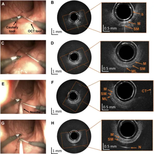
represented in an 8-bit grayscale image. No issues appeared with the operation of the probe and its maneuvering did not influence the quality of imaging. The OCT steerable catheter position was adjusted without the need for motion of the full endoscope, allowing maneuvering of the other interventional tool around the area of interest (Figs.8(A)–8(D)) as well as insertion of a needle using a standard working channel (Fig.8(E)) and injection of methylene blue (Fig.8(G)–8(H)), which is a standard step during ESD procedures.
Fig. 8. Results obtained during experiments in the swine bowel in vivo. (A, C) Screenshots from the white light endoscopic camera of the robotized endoscope showing a cautery tool and the steerable OCT catheter in two position. (B, D) Corresponding OCT cross-sections with layered bowel architecture comprising mucosa (M), submucosa (SM) and muscle (ML) visible in zoomed areas. (E) Screenshots from the white light endoscopic camera showing insertion of the needle using the endoscope’s working channel. (F) Corresponding OCT cross-section with visible reflection from the cautery tool (CT) that was just above the OCT catheter in (E). (G) Needle injection of methylene blue to elevate submucosa. (H) Corresponding OCT cross-section showing mucosa and submucosa layer, followed by the methylene blue clear to near-infrared radiation and strong reflection from the needle (N). In the center of all OCT cross-sections plastic transparent sheath is visible as two concentric rings (S).
4. Discussion
The development of a custom steerable OCT instrument capable of real-time tissue characterization could be used for enhancing the performance of the robotically controlled flexible colonoscope. NURD analysis was performed in order to characterize the rotational distortion given by the regular and steerable catheters. NURD was measured according to the speed of rotation in both catheters. The angle of flexion was measured only for the steerable OCT device. The regular catheter was analyzed in the straight position as it is not steerable. The results presented show how the distortion can be reduced by changing the speed of rotation. Similar curves of the behavior of the distortion were obtained for both catheters showing resonant like dependence with two maxima in the NURD values. Given that the same optical probe was used for both catheters, this behavior can be attributed to a torque coil property. This is an important finding since usually the speed of rotation is determined based on the number of points required for high quality sampling. The inclusion of this methodology could be important in the process of optimization for any endoscopic OCT device.
The quality of images obtained with the steerable OCT catheter can be further improved by optimization of the optical design of the probe and increase of incident power. In the current design, the outer sheath introduces distortions that decrease the lateral resolution [43]. We also used a field assembly fast connector with pre-polished ferrule (FS-FAOC-SCA-SM-P) for proximal termination, which contributed to an overall transmission of the probe of 87%. The choice of mechanical splicing is an interesting low-cost solution, which simplifies the catheter manufacturing procedure and removes the need for specialized equipment. The incident power used in this study was lower in comparison to other endoscopic OCT catheters previously used in the digestive [44] and cardiovascular systems [45], with the range of incident powers between 13 mW and 40 mW and corresponding sensitivities of 105 dB and 98 dB.
In comparison to around 10 cm pullback length available in non-steerable catheters, the proposed steerable catheter provides only 2 cm of pullback. This length was chosen based on the perception of the user when teleoperating the device in the colon phantom. The mechanical interaction test allowed verification of the user ability to manipulate the OCT device as another surgical instrument of the endoscope. The 20 mm sheath length is closer to the length of the normal surgical instrument and at the same time allows for pullback scanning of 20 mm. This aids in imaging of lesion sizes of less than 20 mm, the most difficult to diagnose in the case of colorectal cancer [46]. However, this limitation can be overcome using additional degrees of freedom provided by steerability and robotization of the OCT probe.
To accommodate for the pull wires that bend the catheter, the outer diameter of the steerable device is equal to 3.5 mm. This diameter is currently too large for compatibility with the standard flexible endoscope, in which the outer diameter of the largest available channel is 2.8 mm. As such, this design is limited to use with interventional endoscopes. Other more advanced methods of catheter bending such as those based on soft materials such as shape memory effect catheterization [47,48], concentric tubes [49,50], conducting polymers [51,52], hydraulic pressure driven catheters [53] could be investigated to steer an OCT probe, to further decrease the outer diameter and enable use with other endoscopes adopted into the standard of care.
5. Conclusion
We have presented a novel steerable and robotized endoscopic OCT for real-time assistance during teleoperated endoscopic treatment of colorectal cancer. The NURD analysis shows the dependency of the distortion as a function of the speed of rotation and angle of flexion in the steerable catheter, a methodology that is proposed as part of the optimization process for steerable OCT catheter design. The mechanical interaction test in a colon phantom, as part of the training procedure and sheath size selection has been described. The in vivo swine test demonstrated
the feasibility of steering the OCT device by teleoperation. Mucosa and submucosa layers were visualized by OCT image acquisition in real-time. Rotation, flexion and translation of the device inside the in vivo colon lumen enabled real-time OCT inspection of a larger field of view intra-operatively without the need for changing the position of the main endoscope.
Funding
Fondation ARC pour la Recherche sur le Cancer; ATIP-Avenir; IdEx Strasbourg University. Acknowledgments
The authors would like to thank David Gavarrete Carballo for his collaboration with the graphic illustrations.
Disclosures
The authors declare that there are no conflicts of interest related to this article. References
1. “Global Cancer Observatory,”http://gco.iarc.fr/.
2. T. Matsuda, K. Yamashita, H. Hasegawa, T. Oshikiri, M. Hosono, N. Higashino, M. Yamamoto, Y. Matsuda, S. Kanaji, T. Nakamura, S. Suzuki, Y. Sumi, and Y. Kakeji, “Recent updates in the surgical treatment of colorectal cancer,”Ann. Gastroenterol. Surg.2(2), 129–136 (2018).
3. S. Tanaka, H. Kashida, Y. Saito, N. Yahagi, H. Yamano, S. Saito, T. Hisabe, T. Yao, M. Watanabe, M. Yoshida, S. Kudo, O. Tsuruta, K. Sugihara, T. Watanabe, Y. Saitoh, M. Igarashi, T. Toyonaga, Y. Ajioka, M. Ichinose, T. Matsui, A. Sugita, K. Sugano, K. Fujimoto, and H. Tajiri, “JGES guidelines for colorectal endoscopic submucosal dissection/endoscopic mucosal resection,”Dig. Endosc.27(4), 417–434 (2015).
4. T. Kaltenbach and R. Soetikno, “Endoscopic Resection of Large Colon Polyps,”Gastrointest. Endosc. Clin. N. Am.
23(1), 137–152 (2013).
5. K. Niimi, M. Fujishiro, and K. Koike, “Endoscopic Submucosal Dissection (ESD),” in Advanced Colonoscopy (Springer, 2014), pp. 39–51.
6. B. Dallemagne and J. Marescaux, “The ANUBISTMproject,”Minim. Invasive Ther. Allied Technol.19(5), 257–261
(2010).
7. V. R. Patel, A. S. Tully, R. Holmes, and J. Lindsay, “Robotic radical prostatectomy in the community setting - The learning curve and beyond: Initial 200 cases,”J. Urol.174(1), 269–272 (2005).
8. S. Roy and C. Evans, “Overview of robotic colorectal surgery: Current and future practical developments,”World J. Gastrointest. Surg.8(2), 143 (2016).
9. B. P. M. Yeung and P. W. Y. Chiu, “Application of robotics in gastrointestinal endoscopy: A review,”World J. Gastroenterol.22(5), 1811–1825 (2016).
10. A. De Donno, L. Zorn, P. Zanne, F. Nageotte, and M. de Mathelin, “Introducing STRAS: A new flexible robotic system for minimally invasive surgery,” Proc. - IEEE Int. Conf. Robot. Autom., 1213–1220 (2013).
11. S. Oka, S. Tanaka, I. Kaneko, R. Mouri, M. Hirata, T. Kawamura, M. Yoshihara, and K. Chayama, “Advantage of endoscopic submucosal dissection compared with EMR for early gastric cancer,”Gastrointest. Endosc.64(6),
877–883 (2006).
12. M. J. Gora, J. S. Sauk, R. W. Carruth, K. A. Gallagher, M. J. Suter, N. S. Nishioka, L. E. Kava, M. Rosenberg, B. E. Bouma, and G. J. Tearney, “Tethered capsule endomicroscopy enables less invasive imaging of gastrointestinal tract microstructure,”Nat. Med.19(2), 238–240 (2013).
13. A. Sergeev, V. Gelikonov, G. Gelikonov, F. Feldchtein, R. Kuranov, N. Gladkova, N. Shakhova, L. Snopova, A. Shakhov, I. Kuznetzova, A. Denisenko, V. V. Pochinko, Y. Chumakov, and O. Streltzova, “In vivo endoscopic OCT imaging of precancer and cancer states of human mucosa,”Opt. Express1(13), 432–440 (1997).
14. Y. Zeng, S. Xu, W. C. C. Jr, S. Li, Z. Alipour, H. Abdelal, D. Chatterjee, M. Mutch, and Q. Zhu, “Real-time colorectal cancer diagnosis using PR-OCT with deep learning,” Theranostics (2019).
15. C. L. Leggett and E. C. Gorospe, “Application of confocal laser endomicroscopy in the diagnosis and management of Barrett’s esophagus,” Ann. Gastroenterol. 27(3), 193–199 (2014).
16. J. East, J. Vleugels, P. Roelandt, P. Bhandari, R. Bisschops, E. Dekker, C. Hassan, G. Horgan, R. Kiesslich, G. Longcroft-Wheaton, A. Wilson, and J.-M. Dumonceau, “Advanced endoscopic imaging: European Society of Gastrointestinal Endoscopy (ESGE) Technology Review,”Endoscopy48(11), 1029–1045 (2016).
17. M. J. Gora, M. J. Suter, G. J. Tearney, and X. Li, “Endoscopic optical coherence tomography: technologies and clinical applications [Invited],”Biomed. Opt. Express8(5), 2405 (2017).
18. M. J. Suter, P. A. Jillella, B. J. Vakoc, E. F. Halpern, M. Mino-Kenudson, G. Y. Lauwers, B. E. Bouma, N. S. Nishioka, and G. J. Tearney, “Image-guided biopsy in the esophagus through comprehensive optical frequency domain imaging and laser marking: a study in living swine,”Gastrointest. Endosc.71(2), 346–353 (2010).
19. “NinePoint Medical - See more deeply,”http://www.ninepointmedical.com/.
20. I. J. M. Levink, H. C. Wolfsen, P. D. Siersema, M. B. Wallace, and G. J. Tearney, “Measuring Barrett’s Epithelial Thickness with Volumetric Laser Endomicroscopy as a Biomarker to Guide Treatment,”Dig. Dis. Sci.64(6),
1579–1587 (2019).
21. A. J. Trindade, P. C. Benias, S. Inamdar, C. Fan, A. Sethi, N. Fukami, A. Kahn, M. Kahaleh, I. Andalib, D. V. Sejpal, and A. Rishi, “Use of volumetric laser endomicroscopy for determining candidates for endoscopic therapy in superficial esophageal squamous cell carcinoma,”United Eur. Gastroenterol. J.6(6), 838–845 (2018).
22. C. L. Leggett, E. Gorospe, V. L. Owens, M. Anderson, L. Lutzke, and K. K. Wang, “Volumetric Laser Endomicroscopy Detects Subsquamous Barrett’s Adenocarcinoma,”Am. J. Gastroenterol.109(2), 298–299 (2014).
23. O. M. Carrasco-Zevallos, C. Viehland, B. Keller, M. Draelos, A. N. Kuo, C. A. Toth, and J. A. Izatt, “Review of intraoperative optical coherence tomography: technology and applications [Invited],”Biomed. Opt. Express8(3),
1607 (2017).
24. O. O. Ahsen, K. Liang, H.-C. Lee, Z. Wang, J. G. Fujimoto, and H. Mashimo, “Assessment of chronic radiation proctopathy and radiofrequency ablation treatment follow-up with optical coherence tomography angiography: A pilot study,”World J. Gastroenterol.25(16), 1997–2009 (2019).
25. M. Keenan, T. H. Tate, K. Kieu, J. F. Black, U. Utzinger, and J. K. Barton, “Design and characterization of a combined OCT and wide field imaging falloposcope for ovarian cancer detection,”Biomed. Opt. Express8(1), 124 (2017).
26. W. C. Y. Lo, N. Uribe-Patarroyo, K. Hoebel, K. Beaudette, M. Villiger, N. S. Nishioka, B. J. Vakoc, and B. E. Bouma, “Balloon catheter-based radiofrequency ablation monitoring in porcine esophagus using optical coherence tomography,”Biomed. Opt. Express10(4), 2067 (2019).
27. C. P. Fleming, K. J. Quan, and A. M. Rollins, “Toward guidance of epicardial cardiac radiofrequency ablation therapy using optical coherence tomography,”J. Biomed. Opt.15(4), 041510 (2010).
28. D. Herranz, J. Lloret, S. Jiménez-Valero, J. L. Rubio-Guivernau, and E. Margallo-Balbás, “Novel catheter enabling simultaneous radiofrequency ablation and optical coherence reflectometry,”Biomed. Opt. Express6(9), 3268 (2015).
29. X. Zhao, X. Fu, C. Blumenthal, Y. T. Wang, M. W. Jenkins, C. Snyder, M. Arruda, and A. M. Rollins, “Integrated RFA/PSOCT catheter for real-time guidance of cardiac radio-frequency ablation,”Biomed. Opt. Express9(12), 6400
(2018).
30. H. Wang, W. Kang, T. Carrigan, A. Bishop, N. Rosenthal, M. Arruda, and A. M. Rollins, “In vivo intracardiac optical coherence tomography imaging through percutaneous access: toward image-guided radio-frequency ablation,”J. Biomed. Opt.16(11), 110505 (2011).
31. O. O. Ahsen, H.-C. Lee, M. G. Giacomelli, Z. Wang, K. Liang, T.-H. Tsai, B. Potsaid, H. Mashimo, and J. G. Fujimoto, “Correction of rotational distortion for catheter-based en face OCT and OCT angiography,”Opt. Lett.
39(20), 5973 (2014).
32. Y. Kawase, Y. Suzuki, F. Ikeno, R. Yoneyama, K. Hoshino, H. Q. Ly, G. T. Lau, M. Hayase, A. C. Yeung, R. J. Hajjar, and I.-K. Jang, “Comparison of nonuniform rotational distortion between mechanical IVUS and OCT using a phantom model,”Ultrasound Med. Biol.33(1), 67–73 (2007).
33. N. Uribe-Patarroyo and B. E. Bouma, “Rotational distortion correction in endoscopic optical coherence tomography based on speckle decorrelation,”Opt. Lett.40(23), 5518 (2015).
34. G. van Soest, J. G. Bosch, and A. F. W. van der Steen, “Azimuthal Registration of Image Sequences Affected by Nonuniform Rotation Distortion,”IEEE Trans. Inf. Technol. Biomed.12(3), 348–355 (2008).
35. Wolfgang Drexler, J. G. Fujimoto, and N. Graf, Optical Coherence Tomography, 2nd ed. (Springer, 2010). 36. “OCT Swept Laser Engines — Axsun Technologies,”https://www.axsun.com/oct-swept-lasers.
37. A. M. D. Lee, H. Pahlevaninezhad, V. X. D. Yang, S. Lam, C. MacAulay, and P. Lane, “Fiber-optic polarization diversity detection for rotary probe optical coherence tomography,”Opt. Lett.39(12), 3638–3641 (2014).
38. L. Zorn, F. Nageotte, P. Zanne, A. Legner, B. Dallemagne, J. Marescaux, and M. De Mathelin, “A Novel Telemanipulated Robotic Assistant for Surgical Endoscopy: Preclinical Application to ESD,”IEEE Trans. Biomed. Eng.65(4), 797–808 (2018).
39. M. L. Dufour, C.-E. Bisaillon, G. Lamouche, S. Vergnole, M. Hewko, F. D’Amours, C. Padioleau, and M. Sowa, “Tools for experimental characterization of the non-uniform rotational distortion in intravascular OCT probes,” in (International Society for Optics and Photonics, 2011), 7883, p. 788339.
40. H. Rabinowitz and S. Vogel, The Manual of Scientific Style (Elsevier Inc., 2009).
41. “iPOS3604 VX Intelligent Drive (144 W, CANopen / EtherCAT),” https://www.technosoftmotion.com/en/intelligent-drives-and-motors/ipos-line/ipos3604/ipos3604-vx.
42. K. C. LTD, “Colonoscopy (Lower GI Endoscopy) Simulator Type II LM-107 : KOKEN CO.,LTD.,” http://www.kokenmpc.co.jp/english/products/life_simulation_models/medical_education/lm-107/index.html. 43. J. Xi, L. Huo, Y. Wu, M. J. Cobb, J. H. Hwang, and X. Li, “High-resolution OCT balloon imaging catheter with
astigmatism correction,”Opt. Lett.34(13), 1943 (2009).
44. D. C. Adler, C. Zhou, T.-H. Tsai, J. Schmitt, Q. Huang, H. Mashimo, and J. G. Fujimoto, “Three-dimensional endomicroscopy of the human colon using optical coherence tomography,”Opt. Express17(2), 784–796 (2009).
45. T. Wang, T. Pfeiffer, E. Regar, W. Wieser, H. van Beusekom, C. T. Lancee, G. Springeling, I. Krabbendam, A. F. W. van der Steen, R. Huber, and G. van Soest, “Heartbeat OCT: in vivo intravascular megahertz-optical coherence tomography,”Biomed. Opt. Express6(12), 5021–5032 (2015).
46. Participants in the Paris Workshop, “The Paris endoscopic classification of superficial neoplastic lesions: esophagus, stomach, and colon: November 30 to December 1, 2002,”Gastrointest. Endosc.58(6), S3–S43 (2003).
47. T. Couture and J. Szewczyk, “Design and experimental validation of an active catheter for endovascular navigation,” J. Med. Devices, Trans. ASME12(1), 011003 (2018).
48. P. Dario, R. Valleggi, M. Pardini, and A. Sabatini, “A miniature device for medical intracavitary intervention,” in
Proceedings. IEEE Micro Electro Mechanical Systems(Publ by IEEE, 1991), pp. 171–175.
49. P. E. Dupont, J. Lock, B. Itkowitz, and E. Butler, “Design and control of concentric-tube robots,”IEEE Trans. Robot.
26(2), 209–225 (2010).
50. Y. Baran, K. Rabenorosoa, G. J. Laurent, P. Rougeot, N. Andreff, and B. Tamadazte, “Preliminary results on OCT-based position control of a concentric tube robot,” in 2017 IEEE/RSJ International Conference on Intelligent
Robots and Systems (IROS)(IEEE, 2017), pp. 3000–3005.
51. S. Guo, T. Fukuda, K. Kosuge, F. Arai, K. Oguro, and M. Negoro, “Micro catheter system with active guide wire,” Proceedings - IEEE International Conference on Robotics and Automation1, 79–84 (1995).
52. A. Della Santa, A. Mazzoldi, and D. De Rossi, “Steerable microcatheters actuated by embedded conducting polymer structures,”J. Intell. Mater. Syst. Struct.7(3), 292–300 (1996).
53. Y. Haga, Y. Muyari, T. Mineta, T. Matsunaga, H. Akahori, and M. Esashi, “Small diameter hydraulic active bending catheter using laser processed super elastic alloy and silicone rubber tube,” in 2005 3rd IEEE/EMBS Special Topic