Publisher’s version / Version de l'éditeur:
ASHVE Journal, pp. 1-6, 1952
READ THESE TERMS AND CONDITIONS CAREFULLY BEFORE USING THIS WEBSITE.
https://nrc-publications.canada.ca/eng/copyright
Vous avez des questions? Nous pouvons vous aider. Pour communiquer directement avec un auteur, consultez la
première page de la revue dans laquelle son article a été publié afin de trouver ses coordonnées. Si vous n’arrivez pas à les repérer, communiquez avec nous à [email protected].
Questions? Contact the NRC Publications Archive team at
[email protected]. If you wish to email the authors directly, please see the first page of the publication for their contact information.
NRC Publications Archive
Archives des publications du CNRC
This publication could be one of several versions: author’s original, accepted manuscript or the publisher’s version. / La version de cette publication peut être l’une des suivantes : la version prépublication de l’auteur, la version acceptée du manuscrit ou la version de l’éditeur.
Access and use of this website and the material on it are subject to the Terms and Conditions set forth at
Thermal performance of frame walls
Handegord, G. O.; Hutcheon, N. B.
https://publications-cnrc.canada.ca/fra/droits
L’accès à ce site Web et l’utilisation de son contenu sont assujettis aux conditions présentées dans le site LISEZ CES CONDITIONS ATTENTIVEMENT AVANT D’UTILISER CE SITE WEB.
NRC Publications Record / Notice d'Archives des publications de CNRC:
https://nrc-publications.canada.ca/eng/view/object/?id=e9598088-b1f1-4f38-8c43-a9f54e5c6f33 https://publications-cnrc.canada.ca/fra/voir/objet/?id=e9598088-b1f1-4f38-8c43-a9f54e5c6f33
Ser
TH1
N21r2
no.
5
c. 2
BLDG
'JATIONAL RESEARCH COUNCIL
CANADA
THERMAL PERFORMANCE OF
FRAME WALLS
'""""lk2F0
by
G. 0 . Handegord and N. B. Hutcheon
Reprint of a paper presented at tlie 58th Annual Meeting of
THE A ~ I E H I C : ~ V SOCIETY OF HEATING A N D ~ E K T I L A T I N G E:XGISEEHS. January 28 to 30, 1952
Research I'ayer No.
5
of the
DIVISION OF BUILDING RESEARCH
Ottawa
Thermal Performance
of
Frame
Walls
By G. 0 . Handegord":, Ottawa, and N. B. Hutcheon'i':i:,
Saskatoon, Canada
I N THI.: STIII)Y of the thermal per- formance of the exterior walls of buildings under winter conditions.
-
certain assumptions have been made to permit the application of simple theory based on uni-directional heat flow perpendicular to the wall. This has resulted in a n approach to wall analysis from an overall average-
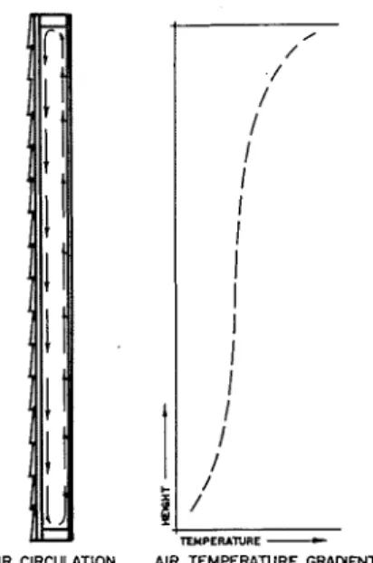
point of view, conditions being as- sumed to be uniform in the plane of the wall. Little attention has been given to departures from these uni- form conditions resultine from the u i ~ ~ f l u e n c e of convective heat transfer in walls wit11 air spaces.Fig. 1 illustrates the possible ef- fects of convection in the a i r suace of a simple wall. Air in the space in contacl- with the warm side will become heated and will rise, increas- ing in temperature as it flows up- ward. Air next LO the cold side of the space will lose heat and will fall, becoming progressively cooler at it descends. The circulation of a i r tlius established within the suace will result in a vertical variation in a i r temperature adjacent to the two 1)ounding surfaces which, for pur- poses of discussion, may be repre- sented I)y the curve in the figure.
--
'Assistant Research OlTicer. Division of Suild- ing Research, NrrIionnl Rc.retr~ch Corrvcil of Cntmdrr.
**Professor of Mechanical Engineering. Uni- versity of Saskatchewan. Member of ASHVE.
Presented at the 58th Annual Meeting of THI:
. ~ M I ! I ~ I C A N SOCII'.L.Y Dl' HEATIKC. A N D VI:N.I.I-
I.ATINCI ESCINI:I:RS. St. Louis, hlo., January I ? > ? .
SUMMARY
-
A preliminary study has been made of the ef- fects of convection in insulated and uninsulated walls containing air spaces. Data are presented which illustrate the vertical var- iation in temperatures and heat flow rates existing in frame walls, when the insulation is ide- ally applied, and when openings occur at the top and bottom of insulations installed to form two air spaces.AIR CIRCUUTION AIR T E M P E m R E G W W T
Fig. 1-Convection in air spaces
If it is assumed that ambient a i r temperatures a r e uniform over the wallt and that film resistances a r e
constant with height, tlic rate of heat flow into tlie wall will b e propor- tional to the air-to-air temperature difference across the inside sheath- ing. T h e rate of heat flow into the wall will therefore decrease with height. Similar r e a s o ~ l i ~ i g may he applied to demonstrate that the rate of Ileal flow out of the wall, across the outside sheathins, ~ v i l l tlecrease f r o m top to hottom.
I t is m o r e th'xn likcly that ambient a i r teml~eratures on lie warm sidc of a wall will also increase with Iieight. howeler, thus tending LO pro-
duce a still greater variation in air space tempcratures. I n addition. the film coefficient for natural convection from I~eateci surfaces increases witit height u p to 2 ft and varies a s ttie
5/41 power of the temperature dif- ference, a s sl~own by Wilkes and Peterson7. This r ariation ill film re-
sistance may also contribute to in- creased variation in the rate of heat tlow into the wall.
A still more serious condition may exist in walls insulated with foil cwrtains o r blanket-type insulations where m o r e than one interior a i r space is formed. When such insula- tions a r e installed in practice. it is unlikely that they a r e always sealed to surrounding structural members. particularly at tlie top and bottom. Even very small o p e r ~ i ~ ~ g s will permit
'Exponent numerals refer to Reierences.
Preprinted from ASHVE J o u n ~ l r . SIICTION. Iletrtitrg, Piping & A h Covdiliotring Printed in U.S.A.
@
J
S E C T I O N
O U R N A L
Controlled Heater Thermostat
W A R M R O O M
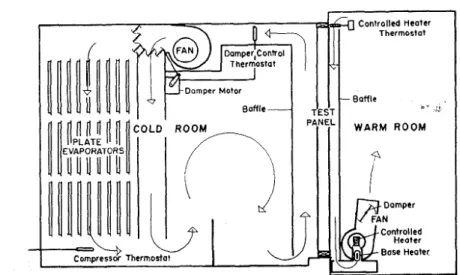
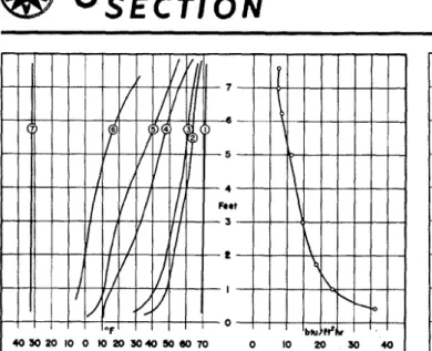
Fig. 2-Cross sectional view of wall panel test apparatus
air circulation between the two spaces since most of the air move- ment adjacent to a heated or cooled surface takes place within a fraction of an inch. If such a circulation exists, the intermediate membrane serves only as an interceptor of ra- diant lieat, and is essentially by- passed by convection. Depending on the extent to which radiant heat en- ergy is absorbed and transmitted tlcross the spaces, sheathing temper- atures will be lower than if no in- sulatio~l were uresent and air circula- tion may be increased. 111 such cases? an even greater vertical heat flow variation may be experienced.
In addition to these possible ef- fects, the presence of gaps in inter- mediate membranes will result in an increase in overall heat transfer. This effect has been demo~islrated by Rowley et al-or blanket type insulations, an increase of 53 per- cent in overall heat transfer being reported when intentional gaps
1 in. in height were left at the top and bottom of the insulation.
The present project was initiated by the Division of Building Research of the Nationd Research Council of
Canada, in cooperation with the Uni- versity of Saskatchewan, to determine the importance of convection effects in standard frame walls with air spaces. The work is being carried out at the Prairie Regional Station of the Division at Saskatoon and this paper presents the resl~lts obtained to date.
Test Apparatus
A cross-sectional view of the test apparatus employed is illustrated in Fig. 2. It consists ol a cold room- warm room combination in which panels up to S ft in height and 7 ft in width may be subjected to steady state heat flow conditions. The re- frigeration equipment for the cold room includes a nominal 5-ton, single-stage, water-cooled condellsing unit using Freon 22 as the refrigerant. Three banks of nine plate-type evapo- lators are installed in the cold room. arranged in a unit as shown in Fig. 2. With this equipment, temperatures al)proacllil~g -40 F iilay be main- lained in the cold room. with a warm room temperature of 70
F.
Forced circulation of air is pro- lided over both sides of the test panel in the direction of natural air movement. This air flow is confined
hy a baffle 011 each side so that more
uniform velocities over the panel sur- faces are ~)rovided. On the warm side, fans and heating equipment are mounted on this baflle and the whole assembly is hung from an overhead track so that it may be swung away to pro\ide access to the test panel. Control ol air temperature in the cold room is accoinplished by on-off operation of the condensing unit ill accordance with the temperature of the air leaving the evaporator. cou- pled with a modulatil~g by-pass damp- er arrangement responding to tlle tem- perature of the air leaving the panel surface. This control arrangement
results in air temperature over the panel being maintained to within 1
F.
T e m ~ e r a t u r e control in the warm room is provided by on-off operation of electric heaters supplemented by a manually-coiltrolled base heater.A
sensitive bi-metallic thermo-regulator "
is used as a controller, operating the heaters through an electronic relay. The base heater is adjusted manually using a variable voltage transformer. Air temperatures a r e co~ltrolled to within 1/2 17 with this arrangement.
Copper-constantan thermocouples are employed for all temperature measurements, using a precision po-
tentiometer. Heat meters a r e used to
determine heat How rates, the thermo- pile emf being recorded with a chart recorder. I n order to use this instru- ment for the purpose, a constant- temperature bias thermocouple is included in the circuit. All thermo- couwle and heat meter leads are carried outside the apparatus and connected to a master switchboard.
A
track is provided on the baffle covering the warm side of the panel in which a sliding heat meter support may be moved by an external cord.his
support carries the heat meterby four spring loaded polystyrene rods which press the meter firmly against the wall surface when the baffle is in place. 111 this way a
single heatmeter is employecl to trav. erse the height of the wall.
Test P r o c e d n r e
A single, basic wall panel 8 ft in height and 5 standard stud spaces in
width was used throughout the tests. The various insulations tested were installed onlv in the three center stud spaces of this panel. Measurements were confined to the center space with the two adjacent spaces serving as guard areas. The 4- by 8-ft plaster- board sheet covering these stud spaces \\,as secured with wood screws so that it could b e removed to alter or re- place the insulation for the different tests.
In conducting a test on each sample wall, air temperatures on the warm and cold sides of the panel were brought to the desired level and were maintained at this point until constant temperature conditions pre-
J
S E C T I O N
O U R N A L
vailed throughout the wall. Under these steady state conditions, a heat- meter traverse was made, the meter indications being recorded for a half tiour period a t each location. A record of this duratio~i .irras found necessary to provide a good value for the average heat flow, in view of the substantial fluctuations which oc- curred iri readings at some positio~is.
At the mid-poirit of the test ruu. temperatures at approximately 50 locatioris throughout the wall were measured a ~ i d recorded.
Air velocities over the panel sur- faces were adjusted to reduce vertical air temperature gradients to an ac- ceptable minimum. The velocities under these coriditions were approx- imately 500 fpm on the cold side and 250 fpm on the warm side. These air flow conditions were maintained constant throughout all tests.
Description of Wall Testecl
The basic wall panel used through- out consisted of %-in. plasterboard, 2- by 4-in. studding spaced 16 in. on cer~ters (actual dimensions 1%- by 3Y8-in.), 25/32- by 10-in. spruce shiplap sheathing, building paper, and 6- by 1/2-in. bevel cedar siding. The exterior siding and sheathing and irlterior plasterboard werc secured with wood screws rather than riails. and the siding was given one prime coat and two finish coats of whitc exterior paint to reduce air infiltra- tion. 111 addition, the joints between
framing arid exterior fi~iish were sealed with masking tape. All spaces between the pallel a ~ i d the test opeli- i ~ l g were packed with wood fiber irisulation.
A total of eight differelit wall
-
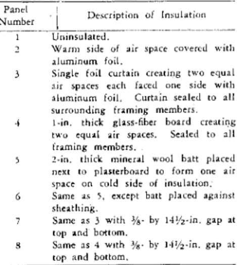
constructions was studied. Only lour different lorms ol irisulatior~ were used, but further variatiolis werc introduced in certain details of appli- cation. The various pa~iels are listed a s follows:Panel
Number .
I
Description o i In~ulation- - ~
I Uninsulated.
1 Warm side of air space c o ~ e r c d with a l u m ~ n u m foil.
3 Single foil curtain creating two equal nir spaces each faced one side with aluminum foil. Curtain senled to nll surrounding framing members.
.i I - i n . thick glass-fiber board creating two equal air spaces. Senled to nll framing members.
5 ?-in. thick mineral wool batt placed next to plasterboard to form one air space on cold side of insulation.
6 Same as 5 , except batt placed agninsl sheathing.
i Same as 3 wit11 '/s- by I.l',/z-in. gap at top and bottom.
8 Snme ns 4 wlth by I.f%-in. gap nt top and bottom.
The 1-in. glass-fiber board insula- tion installed in walls 4 and 8 was used to simulate a blanket insulation since its dimensions and its location in the wall were more strictly defined.
Test Results
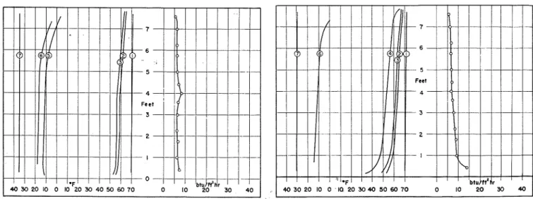
Figs. 3 to 10, inclusive, represent a graphical presentation of the test
results. Each of the figures illus- trates the vertical temperature varia- lion at different planes throughout
he wall, and the corresponding varia- tion ol heat flow into the wall. 111 all figures, the followi~ig numbering systeni has bee11 used to identify the temperature curves.
C u ~ \ r
Nurnbcr
I
1.ocat1on. . . . .-- -.-. . . .
1 \V:;l;lrm side air 1 in. from wall surl:icc.
1 Inside surface of plasterboard.
j Outside surface of plasterboard.
-i Air space, % in. from plasterboard.
5 Air space, %, in. from sheathing. 6 Inside surface of sheathing.
7 Cold side air 2 in. from \\.all surface.
I t should be ~ioted that the thermo- couples in the air space were placed at geometric locations rather than in accordance with air flow lines. For this reason they did not indicate precisely the variation in temperature of the circulating air. I t is possible that the teml)eratiirc gradients shown for these locations illustrate less severe conditions than actually oc- curred.
The heat flow rates given were obtained from observed heatmeter millivoltages using the conversion data provided by the manufacturer of the instrunlent, without further cali- bration.
Heat Flow into Walls with Air Spaces
111 all the walls tested in which the ji~terior finis11 was exposed to an
Fig. 3-Temperature and heat flow variation in Wall N o . 1- Fig. 4-Temperature and heat flow variation in W a l l N o . 2-
O U R N A L
S E C T I O N
L 1
Fig. 5-Temperature and heat flow variation in W a l l No. 3- insulated with single foil curtain creating two air spaces. Foil sealed to surrounding framing members
Fig. 6-Temperature and heat flow variation in W a l l No. 4-
simulared blanket-type insulation. One-inch board, creating two air spaces, sealed to surrounding framing members
air space, tlie rate of heat flow into tlie wall decreased with increasing height. This general feature was in keeping with the simple analysis pre- sented previously in the paper. This same variation was exhibited to a lesser degree by Wall No. 5, aside from the increased heat flow rate measured at the 4\-ft level. It was found on examination after test, that the sealing strip at the junction of the two 4,-ft batt lengths had become detached, and it is likely that some infiltration of air from the outer air space occurred at this discontinuity in the insulation.
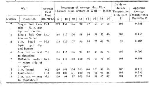
Table 1 is presented to facilitate comparison of the various walls as
to vertical heat flow \-ariation and overall average values. In preparing this table, the mean rate of heat flow into each wall was calculated from the curves of Figs. 3 to 10 and the heat flow rates at different heights xvere expressed as percentages of this value. Tliese percentages are sholvn in the table for the various walls, arranged in order of decreasing mag- nitude in heat flow variation. I t will be noted, however, that the heat flow
into the bottom region ol Walls No.
6 and 8 was a greater percentage of the average than f o r Wall No. 3,
altliough the overall variation for these walls was not as extreme. At)-
parent overall transmittance values
were also calculated by dividing the mean heat flow rate by the inside to outside air temperature difference and multiplying by a factor of 1.25 to bring them to closer agreement with accepted values. This factor for heat~neter readings on frame walls has bee11 proposed also by Prof. E. R.
Queer in a private communication. It will be noted that the transmittance for the uninsulated frame wall is thus brought very close to the ac- cepted value for such a construction. The t~a~lsniittances thus found are given in Table 1. together with the corresponding air-to-air temperature differcnccs. Although ambient con- ditions were not exactly duplicated in all the tests, inside to outside tem- perature differences were sufficiently close to permit somc general com- parisons to be made.
Table 1-Percentage Variation in Rate of Heat Flow with Height for Walls with Air Spaces
It has been proposed by Prol. F. A.
Joy, also in a private communication, that the conversion factors to be applied to heatmeter readings may vary with the resistance of the ma- terial between the heatmeter and the first air spacc encountered in the wall. In view of the doubt which exists on this point it is necessary to consider lleatmeter readings carefully, even for comparative purposes. when there has been some change in the arrangement of material on which the heatmeter has been placed. This will apply particularly to the reading
I
\Y'a l l I ~ i e i i s i
1
Perc;ntage of Average Heat Flow Dist;lnce From h t t o n l o f W a l l - Inclles~
1
E
1
Number
1
Insulation Btu/ft?l,r 61
18 j 301
-12 1 > 4 j 661
78;
90-
7 Single Foil Cur- 15.1 2 2 9 131 106 90 '77 6-1 53 50 I 0 3 0.183
tain - Y8-in. gap top a n d bottom
3 Single Foil Cur- 12.0 159 117 100 98 98 98 83 46 105 0.143
tain - Sealed
8 1-in. board - 1.1.5 173 126 107 96 84 77 69 70 98 0.185
Y8-in. gap top
a n d bottom
6 ?-in. batt - nest 7.9 165 115 106 94 87 83 80 71 102 0.096
to sheathing 2 Reflective surface 16.2 146 117 110 108 96 91 76 56 108 0.188 - warm side of air space 4 1-in. board 9 . 3 130 108 104 l o r l o r 102 89 59 106 0.110 1 Uninsulated 21.1 120 104 101 100 98 96 93 88 103 0.256
5 ?-in. batt - next 6.4 109 98 97 103 lflS 98 97 89 10-1 0.077
to plasterboard -. .. -- - l:$i~
1
hpparent Temperature Difference F Average Tmnslnittance Btu/ft'l~r I:O U R N A L
S E C T I O N
o b ~ a i n c d lo r the Wall No. 5 arrange- menl, in which the mineral ~ v o o l batt was placed against the back of thc plasterboard. T h e other arrangement which might be questioned is that o l
Panel No. 2 ; in all other cases there was a normal a i r space immediately hehind the plaslerboard.
The effect of substituting a reflec- tive foil for one of the surfaces 1)ounding a n air space in an uninsu- lated wall resulted in a decrease in the overall heat transferred. but at the same time increased the varia- tion in heat flow lrom top to bottom. T h e apparent transmiltance at the bottom o l the wall. was in lact, in- creased to. a value greater than the average ~ransmittance fo r the unin- sulated wall.
Wall No. 3. representing a wall with a single-foil curtain insulation, exhibited a greater vertical variation in heat flow than all other walls except f o r Wall KO. 7 in which this same insulation was installed with gaps top and bottom. These results, when considered togelher with the ~'erformance of Wall No. 2. suggest that the effects o l convection are more ~ x o n o ~ i n c e d i n walls insulated with reflecti~ e insulation. This feature is to 1)e expected when il is considered that reflective insulalion reduces radi- ant heat transler to a minimum so that convective transfer predominates. Walls insulated with such materials will therefore exhibit the characleris-
tics of conveclive heat transler to a greater degree.
T h e effect of gaps a t the top a n d bottom o l an intermediate membrane in the air space was to increase the extent o l heat flow variation over that for similar ~valls in ~ v h i c h n o such openings euisted. In the case o l the foil curtain insulation. thesc g a p s r e s u l t e d in a n increase of 68 percent in t h e average heal flow inlo the wall while f o r the simulated 1)lanket-type insulation the increase was al)l)roximately 30 percent. T h e average transmittance values for the
two I\ alls ha! ing improperly sealed
irisulations were al)prouimately equal. lio\\ ever.
In any consideration of the effecls of openings in intermediate mem- l ~ r a n e s in walls. the influence of gaps in exterior o r interior coverings is also suggested. It would b e espectcd h a t openings such as these would have a still greater influence on thc thermal characteristics of a wall. F o r example, in Walls No. 7 and 8. openings at the top and bottom o l the exterior sheathing would result
in cold outside a i r being induced into the wall b y chimney action a n d the inside finish ~vould offer the o n l j prolection against outside weather. it is not LOO unlikely that such gaps
\\ill exist' in some cases since thc trend in recent years has been to increase the I~ermeability of outside portions of the wall to reduce the
possibility of condensation.
(;ails in intcrior coverings fre- cluently r e s u l ~ in practice from the installation of electrical outlets, and im1)rol:er sealing a r o u n d windo\vs a n d doors. The effects of induced circulatioii may b e even more serious in these cases since the a i r entering the wall will contain a considerable amount of moisture. These features, although not covered i n the experi- mental work presented, a r e neverthe- less closely associated with convec- tion in ~valls.
T h e location o l semi-thick batt-type insulation appears to affect both the variation in heat flow with height and the overall average transmittance. From a comparison of t h e test results f o r Walls No. 5 and 6, placement of such iilsulation a t the warm side of the air space h a s advanlages from both points of view. The lower average transmit~ance f o r Wall NO.
5
canno1 be readily explained and suggests thal more extensile investi- gation of this phenomenon is re- quired.Because ol the estremc variations ill heat flow resulting from convec- lion, transmittance values obtained 1)y application of small heatmeters at single points on a wall m a y be quite incorrect in the case of walls with a i r spaces. Full appreciation should be given L O ~ h e s e dislurbing effects iri
assessing performance data for hol- lo\v walls.
Fig. 7-Temperature and heat flow variation in Wall N o . 5- Fig. 8-Temperature and heat flow variation in W a l l N o . 6-
insulated with ?-in. mineral wool batt-air space o n cold side of insulated with 2-in. mineral w o o l batt-air space on warm
@ J
S E C T I O N
O U R N A L
Fig. 9-Temperature and heat flow variation in W a l l No. 7- Fig. 10-Temperature and heat flow variation in W a l l No. 8-
insulated with qingle foil curtain creating two a i r spaces-3/R-i". simulated blanket-type insulation-1 in. board crea'ting two air gap t o p a n d bottom spaces-%-in. g a p t o p and bottom
Temperature Distribution in
Walls with Air Spaces
T h e temperature of the inside sur- faces of walls is a n important feature to b e co~lsidercd ill the assessment of wall performance. Such temperatures are closely associated with the prob- lems of surface condensation and dust markirtg, since both result from a lowering of surface temperature. Usually the temperature of the wall surface is calculated on the basis o l simple theory employing the resist- ance concept. Since this method is based on the assuntption of uni-direc- tional heat flow, considerable error results when it is applied to walls with a i r spaces. Calculation of inside surface temperatures in the usual way, based on a surface film coeffi- cient of 2.7 a s given in
THE
GUIDE'for a velocity of 250 f p m and using the average overall transmittance values from Table 1 provides values in all cases which a r e higher than those found by test, even f o r the upper portions of the walls. T h e variations i n temperature drop f r o m a i r to surface a s given by the dif- ferences between curves 1 and 2 ill Figs. 3 to 1 0 indicate in a general way the n i a r k d deviations in a i r film conductances with height.
*Hk!A'rlNc V~:N.I.II.ATING A I K CONDITIONING GUIDE, p~~bfi~hed by THE AMIRICAK SOCIIXY 01:
HEATING A N D VENTILATING ENGINEERS, , 6 2
\Vorth St., New York 13, N . Y .
I n all cases, inside surface tem- peratures varied a great deal more than u o u l d be expected, temperatures over the lower portions of the walls being c o ~ ~ s i s t e n t l y low. I11 the case o l Wall i\rTo. 7, the effect of improper sealing of the foil curlaill resulted in a surface temperature of approxintatr- ly 35 1: at the 6-in. level. Under such
co~lditions. condensatio~l 011 this area
\vould result if humidities on the \ + a r m side exceeded 27 percent a t 7 0
F.
Temperatures of the inside surfacc of the exterior sheathing in the walls studied also departed widely from thc u ~ l i f o r m conditiolis usually assumed. a s may be noted i n Figs. 3 to 10. T h c temperatures of this surface a r e closely associated with the p r o b l e n ~ of corldetlsation withi11 ivalls and are. therefore, of co~isiderable importance ill ariy analysis of wall performance.
111 general. sheathing temperatures varied with height ill a similar m a n - ner to temperatures of the inside finish and it is obi-ious that wide cliscrel)aticies will exist betweell nctu- a1 values and values calculated h y
simple theory.
Co~~r:lusions
From the results obtained in this p r e l i ~ n i n a r y study of air spaces i n
\\rails it i s coi~clucled that:
1. The convective action within a i r spaces in walls has a much greater inflli- cnce on the temperature distribution and heat flotc pattern than is usually assumed. 2. Tlle variations in heat flow and tenl- peratwe resulting from convection appear to be Inore pronounced in walls containing reflective insulation than in similar walls I~aving normal surfaces.
3. Inlproper sealing of blar~lret-type iri- snlation. or reflective-cnrtain insulation, in- stalled so a s to create multiple air spaces, Inay result in an increase in both vertical heat flow variation a n d in overall trans- nlittance.
1. Preselitly accepted tlleory based on the assnlllption of uni-tiirectional heat flow is entirely inadequate for calculatior~ of tclllperatures ill hollow walls.
5. The use of snlnll heat-flow nieters to c\.oluate the overall tratlsn~ittance of walls tilay lead to et.roneolls results itnlczs a ~>onlplete vertical ~raverse is taken.
Acknowledgnlents
T h e authors wish to express their appreciation for the assistanre given them by M r .
R. R.
Solvaso~l, Assist- ant Research Officer of the National Research Council, in various pllases of the work.References
1. Radiation and Convectioll Across Air Spaces in F r a n ~ e Collstr~~ction, by C. R.
Wilkes and C. hI. F. Peterson (ASHVF.
'I'RAXSAC'~'IOSS, VO~. 43, 1937, p. ,151).
2. ASIlVE RESEARC:H REI~ORT No. 840
- Over-rill Heat Transmission Coefficients Obtained b y Tests a n d Calculation, by F.
R. Rowley, -4, R. .4lgren, and J. I,.
Rlackshaw (ASHVE Tn.ixs~c:~rloxs, Vol.