Publisher’s version / Version de l'éditeur:
Canadian Geotechnical Journal, 12, 1, pp. 13-22, 1975-02
READ THESE TERMS AND CONDITIONS CAREFULLY BEFORE USING THIS WEBSITE.
https://nrc-publications.canada.ca/eng/copyright
Vous avez des questions? Nous pouvons vous aider. Pour communiquer directement avec un auteur, consultez la
première page de la revue dans laquelle son article a été publié afin de trouver ses coordonnées. Si vous n’arrivez pas à les repérer, communiquez avec nous à [email protected].
Questions? Contact the NRC Publications Archive team at
[email protected]. If you wish to email the authors directly, please see the first page of the publication for their contact information.
NRC Publications Archive
Archives des publications du CNRC
This publication could be one of several versions: author’s original, accepted manuscript or the publisher’s version. / La version de cette publication peut être l’une des suivantes : la version prépublication de l’auteur, la version acceptée du manuscrit ou la version de l’éditeur.
Access and use of this website and the material on it are subject to the Terms and Conditions set forth at
Damping in dynamic structure-foundation interaction
Rainer, J. H.
https://publications-cnrc.canada.ca/fra/droits
L’accès à ce site Web et l’utilisation de son contenu sont assujettis aux conditions présentées dans le site LISEZ CES CONDITIONS ATTENTIVEMENT AVANT D’UTILISER CE SITE WEB.
NRC Publications Record / Notice d'Archives des publications de CNRC:
https://nrc-publications.canada.ca/eng/view/object/?id=0d7078d4-231a-4541-ad71-d6a30fa83cad https://publications-cnrc.canada.ca/fra/voir/objet/?id=0d7078d4-231a-4541-ad71-d6a30fa83cad
Damping in Dynamic Structur~Foundation
Interaction
J. H. RAINER
Division ofBrrilditlg Resenrch, Nntionrrl Research Council of Cntlndn, Ottn~vn, Cnnndn KIAOR6
Received February 6 , 1974 Accepted July 30, 1974
Two methods of calculating the damping ratio for structures on compliant foundations are presented. One method employs the calculation of the system damping ratio from the dynamic amplification factor, the other the modal damping ratio from energy considerations. The numeri- cal results for both methods are compared and interpreted. Three sources of damping are considered: inter-storey damping, radiation damping, and foundation material damping. The numerical results demonstrate that with the introduction of compliant foundations the damping ratio of the system can be larger or smaller than that of the corresponding fixed-base structure. Material damping in the foundation soil has been shown to contribute significantly to the over-all damping ratio.
Deux methodes de calcul du facteur d'amortissement des structures sur fondations deformables sont presentees. Une methode emploi le calcul du facteur d'amortissement du systeme B partir du facteur d'amplification dynamique, I'autre le facteur d'amortissement modal bast sur des considerations Cnergetiques. Les resultats numeriques obtenus par les deux mtthodes sont compares et interprites. On considere trois sources d'amortissement: l'amortissement interetage, I'amortissement par radiation et I'amortissement par le mattriau de fondation. Les resultats numiriques dtmontrent que, par suite de I'introduction d'une fondation deformable, le facteur d'amortissement du systeme peut &tre plus grand ou plus petit que celui d'une structure correspondante sur une base fixe. On montre que I'amortissement dans le sol de fondation contribue de f a ~ o n importante au facteur d'amortissement global.
[Traduit par la Revue]
Introduction
Dynamic structure-foundation interaction is of importance in the prediction and interpreta- tion of earthquake and wind effects in structures with compliant foundations. It is particularly significant when structures such as nuclear power plants, high-rise buildings, and towers are founded on moderately or highly compres- sible soils such as till, sand or clay.
Dynamic structure-foundation interaction de- pends on the properties of the structure (in- cluding the foundation elements) and those of the underlying soil. These properties can be expressed by the two most important param- eters affecting dynamic response: natural fre- quency and the damping ratio of the system. The natural frequency is a measure of the degree of 'tuning' of the structure to the char- acteristics of a dynamic disturbance, whereas damping of the system is a measure of the cnergy dissipated and thus is the main param- eter that limits the maximum response. Natural frequencies can be determined simply from the mass and stiffness properties of the structure and the underlying soil; ihis applies to fixed-
base structures as well as to those on compliant foundations. Thc literature on dynamic struc- ture-foundation interaction includes work by Parmelee (1967), Rainer ( 1971 ), Sarrazin et
al. (1972), Meek and Veletsos (1972), Jen- nings and Biclak (1973); and of Roesset et al. (1973) who compared various methods of de- termining modal damping for soil-structure sys- tems. The study now reported tends to support their findings. Although the finite element mcthod can be cmployed with great refinement to the solution of problems of structure-ground interaction (for example, Isenberg and Adham 1972), the application is complex and does not lend itself readily to generalizations. It is hoped that the simpler approach and the numcrical results now presented may advance undcrstanding of the phenomenon.
The present study is limited to incorporating the various sources of damping in a single system damping ratio. Having such a system damping ratio greatly simplifies the response calculations for structures with foundation flexibilities. The complex mathematical com- putations for interaction structures car1 then be Can. Geotech. J . , 12, 13 (1975)
14 CAN. GEOTECH. J. VOL. 12, 1975 replaced by the relatively simple methods avail-
able for single-degree-of-freedom systems. Structural damping, radiation damping, and material damping of the foundation soil are considered. The numerical results obtained from the two methods are compared and in- terpreted. The methods presented are judged to be suitable for design applications for struc- tures having shallow foundations.
Damping in Single-degree-of-freedom Systems (Fixed Base Structure)
The damping ratio h in the single-degree-of- freedom structure may be characterized by the ratio of the damping coefficient C to the critical damping coefficient of the structure C,,:
Critical damping is defined by the relation
[2l C,, = 2 h f i
where k = spring stiffness and m = mass of structure. From the differential equation of motion of a single-degree-of-freedom system subjected to a harmonic base motion with frequency W, the dynamic response factor for
relative displacement of the mass is (for ex- ample, Jacobsen and Ayre 1958):
( ~ 1 ~ 0 ) ~ [31 Ts = [(1 - (w/wo)2)2
+
(2aw/wo)2]1/2 At the undamped resonance frequency w,, themagnitude M , of the dynamic response factor
T,v is related to the ratio of critical damping h
by
With the resonance frequency and the ratio of critical damping known, the response of this typc of oscillator to an arbitrary input such as an earthquake can be found from response calculations or a response spectrum (for ex- ample, Wiegcl 1970).
Damping in Structure-Ground Interaction Systems
General Clzmacte~~istics of Single-storey Interaction Systems
When a single-degree-of-freedom system is placed on a compliant foundation, the follow- ing changes occur:
( 1 ) the fundamental frequency of the sys- tem decreases from that of the fixed-base structure;
( 2 ) energy is removed from the compliant system by the foundation medium during a dynamic disturbance owing to the propagation of waves into this support medium and is com- monly called geometric or radiation damping;
( 3 ) energy is dissipated in the foundation
soil medium by intergranular friction and is commonly called material damping.
When the interaction system shown in Fig. l a is subjected to a base disturbance, the mass inl will undergo a total relative displacement u
composed of the following components : ( 1 )
relative horizontal foundation displacement u,,, ( 2 ) rocking displacement hB, and ( 3 ) inter-
F I X E D h 0 a
REFERENCE
/-TI
FIG. 1. (a) Single-storey structure-ground inter- action system, ( b ) multi-storey structure-ground interaction system.
RAINER: STRUCTURE-FOUNDATION INTERACTION
F R E Q U E N C Y . R A D I S E C
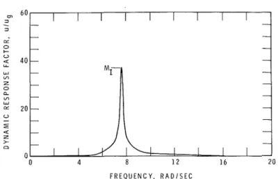
FIG. 2. Dynamic response factor for total relative displacement of top mass.
storey structural displacement us, so that
From the differential equations of motion the dynamic amplification factor for this system can be derived for a harmonic forcing function as presented by Parmelee (1967) and Rainer (1971).
An example of the variation of this factor is plotted in Fig. 2.
Damping Determined from Dynamic Response Factor
As for the single-degree-of-freedom fixed- base structure, damping for the system with a compliant base can be characterizcd by the system damping ratio hl defined as
wherc M I is the magnitude of the dynamic response factor T at the fundamental frequency
w of the interaction system (illustrated in Fig.
2 ) . A relation similar to Eq. [6] was previously employed in the derivation of an equivalent single-degree-of-freedom system for relative displacement in flexible-base systems (Rainer 197 1 )
.
If X, Y, and Z are the dynamic amplifi- cation factors for absolute base displacementu n
+
u,, base rocking 9, and inter-storey dis-placement us, respectively, the dynamic ampli- fication for the total relative displacement of the top mass is
C ~ I
T = ( X - l ) + l r Y + ZValues of M I , the dynamic magnification factor at the fundamental resonance frequency of the flexible system, werc calculated for the set of structural parameters given in Table 1. From these values the system damping ratios
hI were computed and are presented in Tables
3 to 7. In these calculatio~ls the dynamic foun- dation properties for a circular footing given by Bycroft (1956) were employed.
Modal Dampirzg Determined from Energy Considerations
A second method of determining the damp- ing ratio was presented by Novak ( 1 9 7 4 ) and by Roesset et al. (1973). It consists of computing the ratio of the total energy AE dis- sipated in the system to the maximum potential energy E for a particular mode of vibration:
For the interaction structure thc total energy dissipated, AE, during one cycle vibration of a given natural mode is 2T times the summation of the work done by the modal displacements
u n , 129, and u, against the corresponding darnp-
ing forces. As the maximum potential energy in the system is equal to the maximum kinetic energy, the damping ratio h13 of mode j for the entire structure is given by (Novak 1974) :
CAN. GEOTECH. J. VOL. 12, 1975 TABLE 1. Structure and foundation properties Variable Structure group 1
m, 1000 m I 4000 I' 20 12 80 W o 10 X 1, 2,5 G 15 200 P 110 Vs 800
Structure group 2 Units 100 000 Ib sz/in. 100 000 lb sz/in. 60 ft 80, 120, 160 ft 20 rad/s 2, 5 % of critical 66 280 p.s.i. 120 lb/ft3 1600 ft/s
where C is the damping coefficient for various structure. As the fundamental mode shape for
modal coordinates. relative displacement has not changed signifi-
cantly in going from the fixed-base s?ructuie to Determination of Datnping Coeficients 1
the interaction structure, the modal damping The determination of damping coefficients
coefficient C, will have remained substantially required in the numerical evaluation of the
unchanged with the introduction of base flexi-
'Ystem
ratio ' 1 from Eq'151
and the bility. A multi-storey interac- modal damping ratio Xe from Eq. [8] is nowpresented. Inter-storey damping, radiation tion system is illustrated in Fig. l b . damping, and material damping in the founda- Radiation
tion are considered. In general, the damping factor c,, due to
radiation damping, is part of the complex Inter-storey Damping
stiffness Q, for the foundation (Veletsos and Single-storey Structures. For single-storey
structures the damping coefficients C, can be Verbic 1973) :
found from the relation 1121 Ql = K1 (kl
+
ia,~,)Multi-storey Structur.es. As the damping ratio due to relative displacement of a multi-degree- of-freedom structure is usually expressed as a modal damping ratio, the energy dissipated by the structure is determined here from a defini- tion of the modal damping ratio of Eq. 191; C,.,. is determined from Eq. 121. The modal mass M is given by
where x i is the amplitude of the fixed-base mode shape of the structure and tni is storey mass. The corresponding modal stiffness K can be determined from the resonance frequency of the fixed-base structure f,,
The fixed-base frequency is chosen because the damping ratio for inter-storey displacement is generally known or assumed for the fixed-base
where: the subscript j = h, 0 for horizontal motion and rocking of the foundation, respectively;
K j = static stiffness of footing o n an elastic = half-space;
kj
= dynamic spring factor; cj = dynamic damping factor; a, = non-dimensional frequency= wr/V,;
w = frequency, rad/s;
r = radius or equivalent radius of footing;
V, = shear wave velocity of ground;
i = , / - I
The factors kj and cj are functions of coeffi- cicnts that have been calculated and presented for various foundation shapes by, among others, Bycroft (1956), Kobori et al. (1966), Veletsos and Wei (1971 ) , and Veletsos and Verbic (1974), for footings resting on an elastic half- space.
RAINER: STRUCTURE-FOUNDATION INTERACTION 17 structures can also be determined from coeffi-
cients presented by Beredugo and Novak (1972) and Novak (1973, 1974).
For circular foundations 32(1
-
v)Gr[''I
K ,
= 7-
8v (Bycroft 1956)where G = shear modulus, r = radius, and
v = Poisson's ratio for the foundation material. The damping coefficient that represents the energy radiated or dissipated for any particular degree of freedom j is then
Material Damping in the Foundation
Damping in the foundation soil material arises from the energy dissipated through inter- granular friction and reveals itself in a hyster- etic load deformation curve for the soil (Fig.
3 ) . Such a load deformation curve is charac- teristic of viscoelastic materials. The energy dissipated per cycle, A W, may be expressed as a fraction of the total strain energy W by means of the damping ratio D, as employed by Hardin and Drnevich (1972a, b)
.
By making use of the correspondence principle in the theory of visco-elasticity, Veletsos and Verbic (1973) arrived at a most useful ap- proximation: for values of a , up to about two the damping coefficient ( due t o material be- havior may be added linearly to the coefficient
FIG. 3 . Stress-strain ellipse for viscoelastic mate- rial.
cj representing energy radiation from the vibrat- ing foundation:
Veletsos and Verbic (1973 ) defined [ as
it follows then that the total foundation damp- ing coefficient cjt is
This relation enables one t o incorporate the contribution of material damping i n the same manner as was done for radiation damping in the previous sections.
As the material energy dissipation depends to a major degree on the strain levels to which the soil-is sugiected. it is necessarv to obtain the damping data corresponding t o the re- quired loading conditions. For example, for an evaluation of the foundation damping coeffi- cient under wind-induced vibrations the enerev V , dissipated under low levels of strain would usually be desired. For earthquake conditions a strain level approaching that of failure may be needed. These damping parameters can be obtained from appropriate laboratory or field tests or from semi-empirical methods, as for example those outlined by Hardin and Drnevich
(19726).
Numerical Examples
Single-storey Structures on Flexible Foundations
For structure group 1 having parameters given in Tables 1 and 2 the system damping ratio
x13
was calculated using Eq. [8] for struc- tural damping ratios of 1, 2, and 5 % of criti- cal. The results are presented in Table 3. The magnitudes of energy dissipated for horizontal base displacement, rocking, and inter-storey structural displacement are shown in columns W,,, W", and W,, respectively. The associated damping coefficients c,, are also given. Finally, the modal damping ratioxE
obtained from Eq. [8] and the corresponding interaction sys- tem damping ratio A, obtained from the dy- namic amplification factor, Eqs. [6] and [7], are presented.The same method of calculation was used to find the modal and system damping ratio for
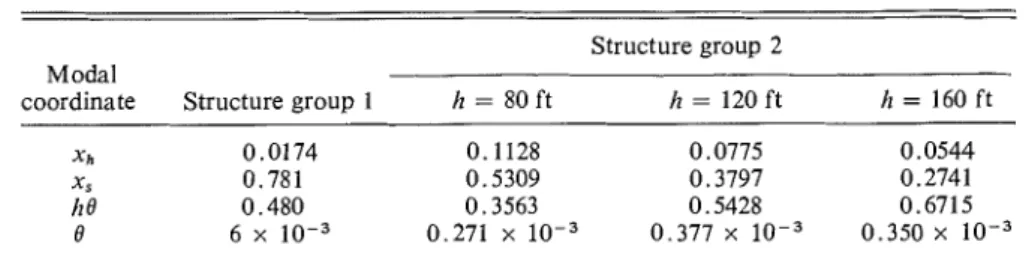
CAN. GEOTECH. J. VOL. 12, 1975 TABLE 2. Mode shapes from eigenvalue calculation
-
-Structure group 2 Modal
coordinate Structure group 1 h = 80 ft h = 120 ft h = 160 ft
xh 0.0174 0.1128 0.0775 0.0544
X s 0.781 0.5309 0.3797 0.2741
/I e 0.480 0.3563 0.5428 0.6715
8 6 x 0.271 x 0.377 x 0.350 x
TABLE 3. System damping for structure group I
A AE (%)
(%) ch Wh W , * W, Wh
+
w,
+
W , Xm,ui2 from Eq. [S] AI (%)1 0.61 84 0 490 574 6460 0.57 -
2 0.61 84 0 980 1064 6460 1.06 1.04
5 0.61 84 0 2440 2524 6460 2.49 2.50
'Rocking damping is finite, but is assumed to be negligible.
structure group 2 whose propertics are also given in Tables 1 and 2. These represent mas- sive, stubby structures such as nuclear reactors. Again, the modal damping ratio hE computed from Eq. [8] and the corresponding system damping ratio, hl, obtained from the dynamic amplification factor are presented in Table 3 for purposes of comparison.
Multi-storey Structures on Flexible Foundations
To determine the damping ratio of the multi- storcy interaction system the transfer function approach may be employed, as for the single- storey structure above. Only the energy method, Eq. [8], is used, however, to calculate the damping ratio of multi-storey structures.
The modal damping ratio for the funda- mental mode is calculated for a structure whose characteristics were determined from ambient vibration measurements (Rainer 1973); struc- tural and foundation parameters have been given by Eden et al. ( 1973). The energy dis- sipated at the base in the form of rocking and radiation damping in the horizontal direction has been determined from theoretical results for rectangular footings (Kobori et al. 1966). For the experimentally determined mode shapes of ub = 0.24, 0 = 0.00184, us = 1, and modal mass xmixi2 = 246 000 lb s2/in., the amounts of energy dissipated in the horizontal and rock- ing base motion and inter-storey displacement are shown in Table 5, which also presents the
modal damping ratios hB calculated from Eq. [8] for an inter-storey damping ratio h of 1, 2, and 5 % .
It may be observed from Table 5 that the computed modal damping ratio hE is substan- tially less than the fixed-base modal damping ratio of h = 5% and slightly less for h = 2 % .
For h = 1 % an increase in system damping
may be seen to be due to the influence of the flexible foundation.
Material Damping in the Foundation
T o illustrate the influence of foundation material damping on the system damping ratio, two assumed levels of material damping are chosen: D = 3 % and D = 15 %
,
and the same value of D is used for horizontal motion as well as for rocking. The structure group 2 and foundation properties of Tables 1 and 2 are used; results without foundation material damp- ing are presented in Tables 3 and 4.The results of the calculations for hE with foundation material damping are presented in Tables 6 and 7. Energy dissipated due to material damping is designated Wov and W,," for rocking and horizontal motion, respectively.
Discussion
A comparison of the system damping ratio
k from the dynamic response factor and modal damping ratio hE from the energy method, Eq. [8], is presented in Tables 3 and 4 for the case without foundation material damping, and in
TABLE 4. System damping for structure group 2 ~1 1
E
A,(%) ‘4 (%)
Case h wo Wh we h W, (Wh
+
We+
Ws) Zrn,u? from from dynamicCAN. GEOTECH. J. VOL. 12, 1975
TABLE 5. Modal damping ratios for multi-storey structure
AE
(73
A ( )
wh
x lo4we
x lo4 W , x lo4 from Eq. [811 4.55 3.31 0.80 1.77
2 4.55 3.31 1.61 1.93
5 4.55 3.31 4.03 2.43
TABLE 6. System damping for structure group 2 with foundation material damping o f D = 0.15
(wh
+
+
ws A~(x)
A[ (%) Case A whc W e c+
Whc+
Wac) from from dynamicNO. ) x lo4 x lo4 x lo4 Eq. [8] response function
TABLE 7. System damping for structure group 2 with fomdation material damping of D = 0.03 Case No. AE (73 from Eq. 181 At (73 from dynamic response function 4.6 5.7 4.0 4.6 3.5 3.9
Tables 5 and 6 for the case with material damping. Throughout the range of parameters considered the comparison between the values of AZ and A, is quite favorable, with a maximum deviation of about 15 to 20% for the low structures considered. This difference decreases as the structures become taller and foundation damping becomes smaller.
The discrepancy in the computed damping ratios may be explained as follows. First, the energy method for computing hE uncouples the modal amplitudes from the damping effects, thereby slightly over-estimating the modal am- plitudes that are associated with high damping coefficients. This is particularly pronounced for low structures where the energy dissipated by the horizontal base motion dominates the other sources of damping, as is evident from Tables
3 and 4, and 5 and 6. The values of he from the energy method will therefore be smaller than A,
from the dynamic response factor. Second, the transfer function at the fundamental resonance frequency also contains small components of the other modes (Novak 1974). This tends to overestimate the damping ratio computed by Eq. [61.
Examination of the values for transfer func- tion amplitude peaks M Z / M , and the resulting damping ratios A, in Table 3 shows that the system damping ratio can be substantially rc- duced in comparison with fixed-base structural damping A. The reduction in system damping ratio is larger for higher values of damping, as is evident from a comparison of the results for
A = 2 % and A = 5 % in Table 4. Furthermore, the system damping ratio becomes smaller the
RAINER: STRUCTURE-FOUNDATION INTERACTION 21
taller the structure. This can be explained by means of the energy method of computing the modal damping ratio. As the modal damping ratio computed from Eq. [8] depends on the sum of the contributions from the various sources of damping, a change in any one of the damping coefficients will affect this damping ratio. Consequently, when the contributions of energy dissipation from material damping and radiation damping are low, structures that have large fixed-base structural damping ratios may experience a substantial reduction in damping ratio when they are founded on compliant bases. On the other hand, for structures having small structural damping ratios an increase in system damping ratio can be expected with the introduction of a compliant base. This effect is illustrated quantitatively by the numerical re- sults for the single-storey structure as well as for the multi-storey building (Tables 3-7).
The results obtained from the energy method illustrate the following principle in a quantita- tive manner: With a compliant foundation, the inajor contribution to the over-all system damp- ine shifts from the structure to the foundation. U
In order to achieve or maintain satisfactory levels of system damping (as is desirable for limiting the response of structures to dynamic loads) adequate sources of damping in founda- tions have to be provided. The damping ratio present for any particular problem can be de- termined to a reasonable degree of accuracy by the energy method outlined herein.
Another important result that emerges from the numerical calculations is that, for the struc- tures considered, the large damping coefficient
CII associated with horizontal base motion yields relatively modest contributions to the total energy dissipated and hence does not
result in large over-all system damping ratios. The reason is that for moderately tall structures the modal amplitude of horizontal base dis- placement is small, compared with the other degrees of freedom. As ihe energy dissipated per cycle is the product of dainping coefficient and the square of the modal amplitude, this product is greatly affected by a small modal base displacement and will, in general, be smaller than the large damping coefficient would lead one to expect. For a structural con- figuration, however, where the ratio of base modal amplitude to rocking and structural dis-
placement amplitudes becomes relatively large, significant contributions to system damping can be expected from the horizontal base com- ponent.
For the multi-storey example an examination of the relative magnitudes of the damping energies Wn, Wo, and W, shows that structural damping is a relatively small proportion of the total damping energy. Consequently, system damping is essentially governed by foundation damping. This is reflected in the results shown in Table 5, where the damping ratios change from 1.77 to 2.43% while the structural damp- ing ratio h varies between 1 and 5 % .
The inclusion of foundation material damp- ing has substantial influence on calculated system damping, as is evident in comparing the results in Table 4 with those of Tables 6 and 7. For the relatively high material damping ratio assumed, D = 0.15, Table
G
shows that thesystem damping ratios hI are substantially larger than their counterparts in Table 4, in which foundation material damping was not included. Similar results, but less pronounced, can be observed in Table 7 for the smaller assumed value of foundation material damping ratio, D = 0.03. An examination in Tables 4, 5 and 6 of the magnitudes of each of the con- tributions to the total energy dissipated indi- cates that energy dissipated as a result of material damping in base rocking is the major contributor when material damping is increased. This is a desirable and welcome trend, since the rocking component is responsible for a large portion of the total kinetic energy of the system in the denominator of Eq. [8]. Without the corresponding damping mechanism in the rocking displacement, the over-all system damp- ing ratio may be considerably smaller than the structural damping ratio, as is illustrated by the results of Table 4.
Conclusion
Two methods of calculation have been pre- sented for determining the over-all damping ratio of structures on compliant foundations. The first makes use of the amplitude of the resonance peak of the dynamic response fuiic- tion for the system; the other is an approximate procedure using energy considerations. Com- parison of cumerical results for a series of single-storey structures demonstrates that the
22 CAN. GEOTECH. results of the energy method compare favor- ably with those obtained by means of the dy- namic response function approach. The energy method of determining damping ratio has also been applied to multi-storey structures; and a procedure for incorporating the contributions of foundation material damping has been de- scribed and illustrated by numerical examples. The numerical results show that the introduc- tion of foundation flexibilities changes the sys- tem damping ratio. Depending on the structural configuration and the degree of foundation material damping present, increased or de- creased system damping ratios can be realized. Quantitative evaluation of the system damping ratio is of importance in determining the re- sponse of structures and foundations to dy- namic disturbances such as earthquakes and wind. The energy method described enables one to pcrform this calculation in a relatively simple manner.
This paper is a contribution from the Division of Building Research, National Research Council of Canada, and is published with the approval of the Director of the Division.
BEREDUGO, Y. O., and NOVAK, M. 1972. Coupled horizon- tal and rocking vibration of embedded footings. Can. Geotech. J. 9(4), pp. 477-497.
BYCROFT, G. N. 1956. Forced vibrations of a rigid circular plate on a semi-infinite elastic space and on an elastic stratum. Philos. Trans. R. Soc. Lond., Series A, 248, Math. Phys. Sci. pp. 327-368.
EDEN, W. J., MCROSTIE, G . C., and HALL, J. S . 1973. Measured contact pressure below raft supporting a stiff building. Can. Geotech. J. 10(2), pp. 180-192. HARDIN, B . O . , ~ ~ ~ D R N E V I C H , V. P. 19720. Shearmodulus
and damping in soils: measurement and parameter effects. J. Soil Mech. Found. Div., A.S.C.E., 98(SM6), pp. 603-624.
1972b. Shear modulus and damping in soils: design
J. VOL. 12, 1975
equations and curves. J. Soil Mech. Found. Div., A.S.C.E., 98(SM7), pp. 667-692.
ISENBERG, J., and ADHAM, S. A. 1972. Interaction of soil and power plants in earthquakes. J. Power Div., A .S.C .E., 98(P02), Proc. Pap. 9242, pp. 273-29 1. JACOBSEN, L. S., and AYRE, R. S. 1958. Engineeringvibra-
tions. McGraw-Hill Book Co., Inc., New York, N.Y. JENNINGS, P. C., and BIELAK, J . 1973. Dynamics of
building-soil interaction. Bull. Seism. Soc. Am. 63(1), pp. 9-48.
KOBORI, T., MINAI, R., and KUSAKABE, K . 1966. Dynami- cal ground compliance of rectangular foundation. Proc. 16th Jap. Nat. Congr. Appl. Mech., pp. 301-306. MEEK, J . W., and VELETSOS, A. S. 1972. Dynamic analysis
and behavior of structure-foundation systems. Dep. Civ. Eng., Rice Univ., Houston, Texas, Str. Res. Rep. No. 13.
NOVAK, M. 1973. The effect of embedment vibration on footings and structures. Proc. 5th World Conf. Earth- quake Eng., Rome, Pap. No. 337.
1974. Effect of soil on structural response to wind and earthquake. J. Earthquake Eng. Struct. Dynam. 3(1), pp. 79-%.
PARMELEE, R. A. 1967. Building-foundation interaction effects. J. Eng. Mech. Div., A.S.C.E. 93(EM2), Proc. Pap. 5200, pp. 131-152.
RAINER, J. H . 1971. Structure-ground interaction in earth- quakes. J. Eng. Mech. Div., A.S.C.E., 97(EM5), Proc. Pap. 8422, pp. 1431-1450.
RAINER, J . H. 1973. Determination of foundation flexibilities ofstructures. Proc. 5th World Conf. Earth- quake Eng., Rome, Proc. Pap. No. 254.
ROESSET, J., WHITMAN, R. V., and DOBRY, R. 1973. Modal analysis for structures with foundation interac- tion. J. Struct. Div., A.S.C.E.,99(ST3),pp. 399-416. SARRAZIN, M. A., ROESSET, J. M., and WHITMAN, R. V. 1972. Dynamic soil-structure interaction. J. Struct. Div., A.S.C.E., 98(ST7), pp. 1525-1544.
VELETSOS, A. S., and VERBIC, B. 1973. Vibration of vis- coelastic foundations. J. Earthquake Eng. Struct. Dynam. 2, pp. 87-107.
1974. Basic response functions for elastic founda- tions. J. Eng. Mech. Div., A.S.C.E., 100(EM2), Proc. Pap. 10483, pp. 189-202.
VELETSOS, A. S . , and WEI, Y. T. 1971. Lateral and rocking vibrations of footings. J. Soil Mech. Found. Div., A.S.C.E., 97(SM9), pp. 1227-1248.
WIEGEL, R. L. (Editor). 1970. Earthquake engineering. Prentice Hall, Inc., Englewood Cliffs, N.J.