READ THESE TERMS AND CONDITIONS CAREFULLY BEFORE USING THIS WEBSITE. https://nrc-publications.canada.ca/eng/copyright
Vous avez des questions? Nous pouvons vous aider. Pour communiquer directement avec un auteur, consultez la première page de la revue dans laquelle son article a été publié afin de trouver ses coordonnées. Si vous n’arrivez pas à les repérer, communiquez avec nous à PublicationsArchive-ArchivesPublications@nrc-cnrc.gc.ca.
Questions? Contact the NRC Publications Archive team at
PublicationsArchive-ArchivesPublications@nrc-cnrc.gc.ca. If you wish to email the authors directly, please see the first page of the publication for their contact information.
NRC Publications Archive
Archives des publications du CNRC
This publication could be one of several versions: author’s original, accepted manuscript or the publisher’s version. / La version de cette publication peut être l’une des suivantes : la version prépublication de l’auteur, la version acceptée du manuscrit ou la version de l’éditeur.
Access and use of this website and the material on it are subject to the Terms and Conditions set forth at
Vibration and possible building damage due to operation of
construction machinery
Ferahian, R. H.; Hurst, W. D.
https://publications-cnrc.canada.ca/fra/droits
L’accès à ce site Web et l’utilisation de son contenu sont assujettis aux conditions présentées dans le site LISEZ CES CONDITIONS ATTENTIVEMENT AVANT D’UTILISER CE SITE WEB.
NRC Publications Record / Notice d'Archives des publications de CNRC:
https://nrc-publications.canada.ca/eng/view/object/?id=115cf619-a12c-438b-a42d-50076c6eb545 https://publications-cnrc.canada.ca/fra/voir/objet/?id=115cf619-a12c-438b-a42d-50076c6eb545
A N A L yZEa
Vibration and Possible Building DamageDue to Operation of Construction Machinery R. H. Ferahian, Research Officer, Building Physics Division, Division of Building Research, National Research Council of Canada, Ottawa
and
W. D. Hurst, City Engineer and Commissioner of Buildings Winnipeg, Manitoba.
During construction or maintenance of build- ings and roads, the operation of construction machinery and vehicles causes vibrations in near- by structures. Complaints of damage to structures resulting from these vibrations are frequent, par- ticularly when the vibration experienced is judged by occupants to be severe. This paper deals with the vibrations caused by the operation of ma- chinery during the maintenance of roads in the city of Winnipeg, Manitoba. Members of the Division of Building Research, National Research Council of Canada, at the request of Mr. W. D. Hurst, conducted the investigation with the col- laboration of the interested authorities in the city of Winnipeg. The purpose of this study was to determine the levels of vibrations and to examine the possibility of their causing damage to build- ings.
Description of Buildings Tested
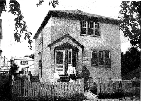
Building No. 1 (Figure l ) , was approximately 60 years old, a timber duplex with a basement. It had a foundation wall composed of 7- x 8- x 25- inch concrete blocks extending five feet below grade. The timber construction was of the con- ventional type with the walls eight inches thick from the interior plaster to the exterior stucco. Building No. 2 (Figure 2 ) , was the cenbal house of a new (not yet occu ied) three-unit row. Its eight-inch reinforced concrete foundation wall was five feet deep with one foot above grade. It was carried on 14-inch reinforced concrete piles driven to refusal. The exterior wall incorporated four-inch face bricks; the party wall was eight-inch brick. The rest of the frame was of conventional timber construction.
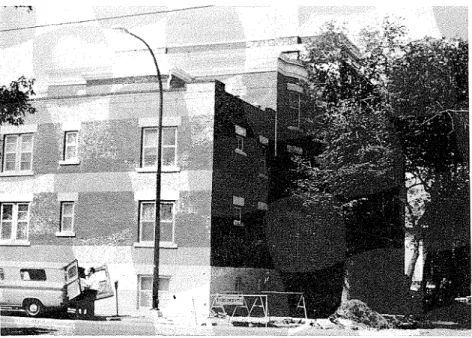
Building No. 3 (Figure 3 ) was a 60-year-old apartment block. It was composed of three sections, namely, four stories and a basement, three stories and a basement, two stories and a basement. The comer of the last section was instrumented. The construction was of brick bearing walls with concrete block foundation walls (similar to those of building No. 1 ) . It was carried on 16-inch timber concrete piles extending to glacial till 45 feet below grade (38 feet below the footings). The section comprising the four stories and basement was carried on an additional four 26-inch diameter concrete caissons belled at the glacial till.
R e p r i n t e d f r o m t h e P r o c e e d i n g s o f t h e 1968 P u b l i c Works C o n g r e s s a n d Equipment Show
Figure 1. Building No. 1-Duplex (110 Robinson St.)
Figure 2. Building No. 2-Row Housing (2/117 Robinson St.)
Figure 3. Building No. 3-Apartment Building (404 Qu'Appelle St.)
Soil and Foundation Conditions in Winnipeg
The city of Winnipeg is built upon sedimentary lake deposits dating back to the Pleistocene period when the area was inundated by a vast body of water called Lake Agassiz. The limestone bedrock is 60 to 70 feet below ground level. Table I shows soil properties outside building No. 1. The strata deeper than eight feet below the surface are approximate.1
TABLE I
SOIL PROPERTIES OUTSIDE BUILDING NO. 1
Unconfined
Depth Compression Molsture
ft
.
Description Strength, k.s.f. Content, %0-1 Black top soil
-
-
1-3 Black silty soil
-
-
3-4 Light to chocolate 4.4 37
brown silty clay-stiff; gypsum crystals
4-5 Light to dark brown 3.1 31
clay-stiff
5-6.5 Light to dark brown 2.0 39
mottled clay-medium
6.5-8 Dark brown mottled 2.4 41
silty clay; gypsum crystals
Subsequent soil strata to depth of 65 ft. are as followsl:
-
approximately 20 ft. of dense, chocolate-colored clay-
approximately 20 ft. of dense blue clay-
2 ft. of boulders and ground-up limestone-
2 ft. of medium-dense glacial till-
5 to 10 ft. of dense glacial till-
limestone bedrock at depth of approximately 65 ft.Winnipeg clays are notorious for shrinkage on drying and subsequent swelling and heaving when wetted after rainfalls2. Drying shrinkage cracks sometimes extend to depths greater than 10 feet. The amount of heave is practically independent of the weight of the building and its effect is very similar to that of unequal settlements of buildings. It leads to cracked base- ment floors and walls, partition walls and exterior walls.
The foundations of heavy buildings in Winnipeg are generally carried by caissons extending to bedrock. Medium-size buildings have spread footing foundations extending to the layers of chocolate-colored or blue clay. Some- times they are carried on wooden or reinforced concrete piles driven to refusal at the medium-dense glacial till. Foundations of heavy and medium- size buildings are thus naturally extended to depths unaffected by shrinkage with its resulting heaving action. This is not true for ordinary residential construction, where the foundation is carried to approximately five feet be- low grade. Thus, the majority of houses in Winnipeg, e.g. building No. 1,
are subjected to considerable differential movements in their foundations after extended dry periods. Sometimes the resultant cracks are attributed by the complainants to vibrations caused by machinery or traffic.
Instrumentation and Experimental Procedure
Conclusions of many researchers, especially in the field of blasting vi- brations3, have indicated that particle velocity is the most useful indicator of the onset of damage. Consequently, it was decided that only particle velocities would be monitored in this investigation.
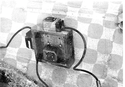
Vibration observations were made with a velocity-sensitive moving coil transducer with a natural period of 2.5 sec. (MB, Type 120). The trans- ducers were connected through appropriate amplifiers to the galvanometers in a multi-channel recording oscillograph that had direct-writing photo- graphic paper. The transducer pickups were attached to mounting brass pans, which were then screwed to the wall. Figure 4 shows three pickups mounted on the foundation wall to measure the velocities in three mutually perpendicular directions.
Building No. 1 was instrumented on the front foundation wall in two places: one foot above the basement slab and six inches above grade. The front wall was also instrumented one foot above the second-floor slab. All three components of motion were examined in earlier tests, but later only the vertical and longitudinal (perpendicular to plane of the wall and axis of the street) were recorded as the transverse component was invariably much smaller than the other two components. It was also noted that the vibrations on the foundation wall were usually greater at grade level than those a t lower levels. Consequently, building No. 2 was only instm- mented on the foundation wall six inches above grade and also on the front wall one foot above the second-floor slab. The pickup for the vertical velocity at the second station was placed on the window sill. The foundation wall (along Qu'Appelle Ave.) of building No. 3 was instrumented at its southeast comer one foot above grade.
Figure 4. Typical Transducer Installofion
The vibrathns caused by the following machinery were recorded at a few distances from the buildings:
1. Mobile rubber-tired pavement breaker, model G-400 as manufactured by Arrow Manufacturing Company, Denver, Colorado. (Hammer weight 1100 Ibs., approximate drop 10 feet).
2. Crawler loader, model 977h as manufactured by Caterpillar Tractor Company of Peoria, Illinois. (Weight 38,600 Ib)
.
3. Hydraulically operated rubber-tired back-hoe, Hopto model 345A-TM as manufactured by Warner and Swasey Company, Cleveland, Ohio.
(Weight 36,000 lbs.)
.
4. Vibratory roller, model BTVR as manufactured by Western Products, Milwaukee, Wisconsin. (Nominal two-ton capacity, weight 3600 lbs., rated vibration frequency 1200-1600 vibrations per minute).
5. Vibratory plate compactor, model VPG16OKB as manufactured by Wacker Corporation, Hartford, Wisconsin. (Four h.p. at 4000 r.p.m., rated at 5000 blows per minute).
6. Air-operated jack hammers.
7. Loaded concrete transit mixer truck, Jaeger model 7% H mixer mounted on Ford T850 truck with tandem rear axles. (Weight approximately 56,000 pounds including eight cubic yards of concrete).
Recordings were made of the vibrations resulting from driving the con- crete mixer truck at various speeds down Robinson Avenue and over a wooden ramp three inches in height placed across the road to simulate the worst-of bumps ordinarily experienced on urban streets when vehicles pass over depressions or potholes. These vibrations were compared with those caused by a family car (Chevrolet). Also recorded were vibrations due to
footsteps, jumping on floors, slamming doors, and pulling down an elm tree outside building No. 3.
Wave Forms
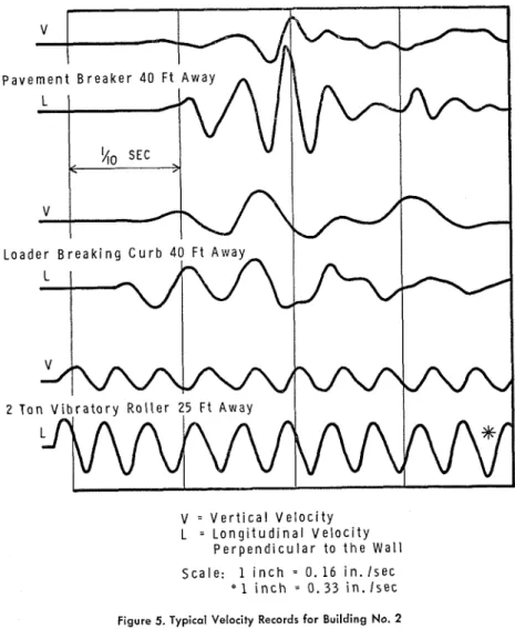
The form of some typical disturbances is illustrated in Figure 5. These records show the particle velocities for the foundation wall of building No. 2. It can be seen from these traces that the vertical velocities are usually less, than the longitudinal ones. Sometimes the two velocities are of the same order of magnitude. Consequently, only the longitudinal velocities will be presented in the subsequent discussion.
The wave forms of vibrations caused by the machines in question can be assigned to either of two categories: akin to single shot vibrations or to
V = V e r t i c a l V e l o c i t y
L = L o n g i t u d i n a l V e l o c i t y
P e r p e n d i c u l a r t o t h e W a l l S c a l e : 1 i n c h
-
0. 1 6 i n . l s e c* 1 i n c h
-
0 . 3 3 i n . I s e ccontinuous vibrations. Examples of-the &st category are the vibrations caused by pavement breakers and the majority of the vibrations arising from the loader breaking the curbs or. sidewalks. These wave forms are very similar to those produced by blastinga. The vibration is mainly concentrated
in one or two initial pulses followed by a quickly damped wave train. TABLE I1
ESTIMATED MAXIMUM ACCELERATIONS AND FREQUENCY
RANGE FOR BUILDINGS NOS. 1 AND 2
Acceleration, Frequency
Source of Vibration %g Range, Hz
'
Pavement breaker Loader breaking curb %ton vibratory roller Vibro-plate compactor and
jack hammers Tr&c heavy light Jumpinf indoors Heavy ootsteps Slam door
'Hz-Hertz, the unit of frequency. "90 Hz most common.
130 Hz noted sometimes.
It is equivalent to cycles per second.
TABLE I11
VIBRATIONAL VELOCITIES MEASURED ON THE FOUNDATION WALL FOR BUILDING NO. 3
Velocities, in./sec. Vertical Perpdic-ulur
Source of Vibration to wall
Pavement breaker 3% ft. away (full drop
of blade) 0.301 0.601
Loader removing curb 12 ft. away 0.15 0.752
Loader unloading in truck 0.02 0.05
Pulling down elm tree stump, 12 ft. away, stump dimensions: 3 ft, diameter
at base and 11 ft. high 0.02 0.113
Push and pull tree 0.01 0.024
Footsteps on sidewalk 0.01 0.01 6
Slam door 0.020 0.02"
lacceleration
-
90% g, where g is the acceleraition of gravity;frequency 70 Hz.
Zacceleration
-
35% g at-
70 Hz.3acceleration 10% g at
-
50 Hz. (This high acceleration peak was caused by the snapping of a 3-in. diameter root.)4frequency
-
10 Hz.6acceleration
-
10-20% g; frequency 60-150 Hz.Examples of continuous vibrations are those produced by a 2-ton vibratory loader and the vibra-plate compactor. The vibrations caused by the con- crete mixer b c k when driven over the three-inch ramp were very much like the central traces of Figure 5. The wave forms due to jumping, slam-
ming doors, or pulling down trees were more complex with a profusion of higher frequencies (Tables I1 and 111). Accelerations and displacements can be obtained by differentiating or integrating these traces respectively.
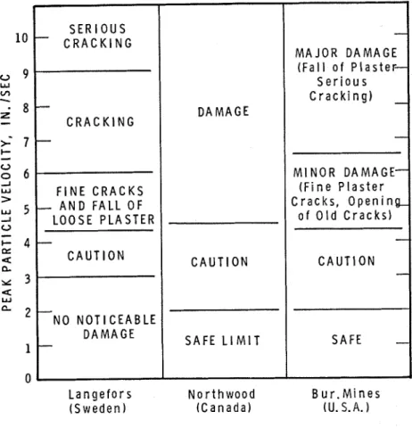
Proposed Criteria for Limiting Damage and the Observed Vibration Levels Figure 6 shows criteria for damage as related to the particle velocity from different researchers. In Canada3 the velocity corresponding to the threshold of damage is taken at three inches per second. As mentioned earlier, those vibrations that are akin to the single shot vibrations could be treated in a manner similar to that for blasting vibrations. As the operation of machinery producing such vibrations is usually in areas of high occupancy, and the subsequent vibrations are generally not monitored, it therefore seems reasonable to specify a lower threshold of damage. It is proposed here
M A J O R D A M A G E S e r i o u s C r a c k i n g )
l o
U 9 W v,-
Z-
2:
5
U3
W >5
d U-
I- E u CL Y 3 4 W*
1
0
M I N O R D A M A G E ( F i n e P l a s t e r C r a c k s , O p e n i n o f O l d C r a c k s ) C A U T I O N14
L a n g e f o r s N o r t h w o o d ( S w e d e n ) ( C a n a d a ) S E R I O U S-
C R A C K I N G8 -
C R A C K I N G 7 - F I N E C R A C K S-
A N D F A L L O F L O O S E P L A S T E R 4 - C A U T I O N -NO N O T I C E A B L E D A M A G E-
B u r . M i n e s (U. S.A. D A M A G E C A U T I O N S A F E L I M I Tto use 1.5 inch per second. There is evidence that damage is not a function of the number of applications of the stress cycle provided this number lies well below the fatigue life of the material" Prudence dictates, however, that for continuous vibrations due to the operation of construction machinery the proposed threshold of damage be made equal to one inch per second.
D l S T A N C E F R O M FRONT WALL, FT L
-
-
-
-
-
B u i l d i n g No. 1 D u p l e x v-
v I-
.
I . ' v I-
v-
-
v-
.
-
-
I .-
.
C )-
-
$ 2 '2-
4-
-
-
+
-
-
+
- C o n c r e t e B l o c k-
F o u n d a t i o n W a l l I+
LEGEND v A r r o w P a v e m e n t B r e a k e r IV L o a d e r B r e a k i n g C u r b v2= A r r o w P i v e m e n t B r e a k e r V i b r a t o r y R o l l e r 25 F t a n d 2 T o n V i b r a t o r y R o l l e r A w a y . V i b r o - P l a t e 25 F t F r o m B u i l d i n g C o m p a c t o r 1 0 F t A w a y I L o a d e r B r e a k i n g C u r b s 2 T o n V i b r a t o r y R o l l e r ID L o a d e r D u m p i n g+
V i b r o - P l a t e C o m p a c t o r 4 J a c k H a m m e r s 02 J a c k H a m m e r s 0 B a c k H o e ( H o p t o ) D i g g i n gFigure 7. Vibrational Velocities Caused by the Operation of Construction Machinery
3
I
-
--
v-
B u i l d i n g N o . 2 R o w H o u s i n g-
-
v 40-
v25 I 'J V : v I-
-
-
I v t--
v 3.
.
d-
I 0.
-
+
+
-
-
-
-
-
--
-
R - C F o u n d a t i o n W a l l-
o n C o n c r e t e P i l e sI
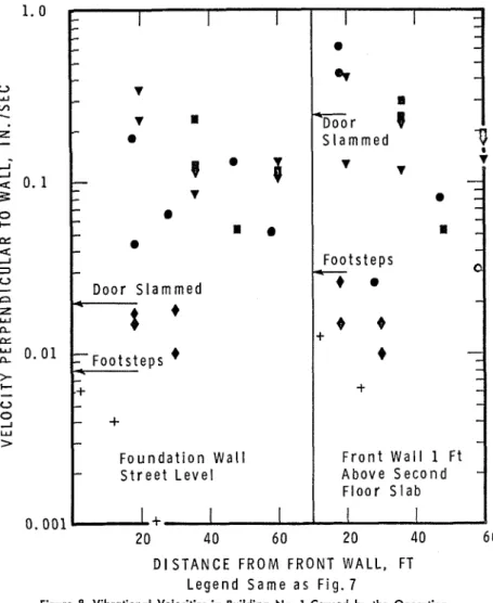
Figure 7 shows the longitudinal velocities recorded on the foundation walls (six inches above grade) for buildings one and two for a few distances from the source of disturbance. It can be deduced from this figure that: 1. the velocities are nowhere higher than one inch per second;
2. the vibrations caused by the pavement breaker and loader when break- ing sidewalks or curbs, and the 2-ton vibratory roller are usually of comparable magnitudes;
3. the vibrations generally are less the greater the distance of the machinery from the buildings;
D l S T A N C E F R O M F R O N T W A L L , FT L e g e n d S a m e a s F i g . 7
Figure 8. Vibrational Velocities in Building No. 1 Caused by the Operation of Construction Machinery
4. vibration amplitudes for the two different buildings are usually of com- parable magnitudes and never different by more than one order of magnitude;
5. the simultaneous use of machines produces vibrations of amplitudes smaller than the sum of the amplitudes due to the use of the machines separately.
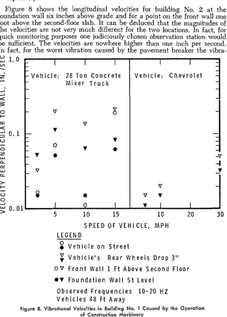
Figure 8 shows the longitudinal velocities for building No. 2 at the foundation wall six inches above grade and for a point on the front wall one foot above the second-floor slab. It can be deduced that the magnitudes of the velocities are not very much different for the two locations. In fact, for quick monitoring purposes one judiciously chosen observation station would be sufficient. The velocities are nowhere higher than one inch per second. In fact, for the worst vibration caused by the pavement breaker the vibra-
0 w 1 . 0 L A 1 Z
-
-
-
I
I
II
I
-
-
-
-
- V e h i c l e : 28 T o n C o n c r e t e V e h i c l e : C h e v r o l e t-
-
-
M i x e r T r u c k-
-
-
--
v
8
-
v
v
-
-
-
-
-
-
v
-
-
0v
-
a
l- v
a
-v
-
-I
v
-
v
-
-
v
8
a
v
v
I 0 I 'I I I S P E E D O F V E H I C L E , M P H L E G E N D V e h i c l e o n S t r e e t V e h i c l e ' s R e a r W h e e l s D r o p 3 "o v
F r o n t W a l l 1 F t A b o v e S e c o n d F l o o ra v
F o u n d a t i o n W a l l S t L e v e l O b s e r v e d F r e q u e n c i e s 1 0 - 2 0 H Z V e h i c l e s 4 8 F t A w a yFigure 8. Vibrational Velocities in Building No. 1 Caused by the Operation of Construction Machinery
tions recorded are removed from the proposed threshold of damage of 1.5 inch per second by a factor of 2.5. Even for the 2-ton vibratory roller the worst vibrations are removed from the proposed threshold of damage of one inch per second by a factor of approximately 2. It s b d d be noted, however, that to be on the safe side this vibratory roller should not be used at distances closer than 10 feet from the buildings. In fact, for these smaller distances vibro-plate compactors are usually utilized.
Table I11 presents the recorded velocities and the corresponding ac- celerations (deduced from the maximum slopes of the traces) for the founda- tion wall of building No. 3. Even at short distances from the building, the velocities were nowhere greater than one inch per second. The high acceleration accompanying the use of the pavement breaker indicates, however, that it might well be more prudent not to use the full drop of the blade for distances less than 10 feet from the building.
The vibrational velocities caused by slamming doors, heavy footsteps, and jumping indoors (Tables I1 and I11 and Figure 8 ) are comparable to s0m.e of the worst recorded vibrations. In fact, the accompanying accelera- tions would be higher than those caused by the operation of the con- struction machinery. The corresponding displacements are, however, much smaller because of their higher frequencies. Displacements could be esti- mated approximately from the velocities or accelerations by dividing by 2srf and (2srf) respectively where f is the frequency in Hz.
Finally, Figure 9 shows the worst vibrations caused by the 28-ton con- crete mixer truck being driven over a three-inch ramp at 1 5 m.p.h. are only 0.2 inch per second at 10 to 20 Hz. This is much lower than the 1 to 1.5 inch per second proposed threshold of damage. The gaximum velocity produced by a Chevrolet under comparable conditions is of the order of 0.02 inch per second, i.e., l/lOth of those caused by the 28-ton concrete mixer truck (see also Table 111).
Conclusions
Vibrational velocity levels in buildings due to the operation of con- struction machinery similar to those described in this study at similar distances from buildings, and for similar foundations, would be less than one inch per second. It has been found1 that vibrational levels are, in fact, smaller for frozen ground conditions in winter. In addition, previous studies on blasting vibrations3 show that the thresholds of damage are virtually the same for houses on till or rock. I t is believed, therefore, that it would be highly improbable that damage to buildings similar to those tested could be caused by the judicious operation of similar construction machinery or traffic nearby.
References
(1) Sutherland, H. B., "A Study of the Vibrations Produced in Structures by Heavy Vehicles," Proceedings of the Thirtieth Annual Meeting of the
Highway Research Board, December 1950, p. 406-419 (DBR 27).
( 2 ) Hamilton, J.
J.
and G. 0. Handegord, "House Basements on PrairieClays," Canadian Builder, Vol. XIV, No. 9, September 1964, p. 28 (DBR Housing Note 20).
( 3 ) Northwood, T. D. et al., "Building Vibrations and Building Damage,"
The Engineer, Vol. 215, No. 5601, May 31, 1963, p. 973-978 (NRC
7485).
(4) Steffens, R. J., "Some Aspects of Structural Vibration," Proceedings of
the Symposium on ' V V i a t w n . i n Civil Engineering," Imperial CoE
lege of Science and Technology, London, April 1965, Published by Butterworth, page 7.
Acknowledgments
The author's thanks are here extended to Mr. Denis Wasylyniuk, Di- vision of Building Research, National Research Council; and to Mr. Magnus Bayne, Design Engineer, and Mr. Ronald V. Houghton, Construction En- gineer, Engineering Department, City of Winnipeg, for their assistance on the project.