Highly Elastic Polyrotaxane Binders for Mechanically
Stable Lithium Hosts in Lithium-Metal Batteries
Dong-Joo Yoo, Ahmed Elabd, Sunghun Choi, Yunshik Cho, Jaemin Kim,
Seung Jong Lee, Seung Ho Choi, Tae-woo Kwon, Kookheon Char, Ki Jae Kim,*
Ali Coskun,* and Jang Wook Choi*
specific capacity reaches 2060 mAh mL−1 or 3860 mAh g–1, and the thermodynamic redox potential is as low as −3.04 V versus standard hydrogen electrode (SHE). Nevertheless, the inherent drawbacks of the Li-metal anodes such as continuous electrolyte decomposition and dendrite growth over cycling still pose formidable challenges, rendering the given tech-nology to linger at a research stage.[2]
A variety of approaches have been introduced to resolve the aforementioned issues and increase Coulombic efficiency (CE) of the Li-metal anodes. Some of those approaches include artificial SEI layers,[3] selective Li deposition,[4] elec-trolyte additives,[5] high concentration salts,[6] solid electrolytes,[7] and polymer electrolytes.[8] In spite of substantial improvement with these approaches, there still remains some limitations for practical applications that require certain levels of areal current density and capacity.
Among the reported strategies, the inte-gration of 3D conductive network acting as a host for Li storage has been proved to offer reliable operation with Li-metal anodes. One of the mechanisms in alleviating the Li dendrite growth by 3D con-ductive networks is the reduction of effective current density. For a given electrode area, the 3D network lowers the effec-tive areal current density, a critical parameter in determining the magnitude of dendrite growth in correlation with Sand’s Despite their unparalleled theoretical capacity, lithium-metal anodes suffer
from well-known indiscriminate dendrite growth and parasitic surface reactions. Conductive scaffolds with lithium uptake capacity are recently highlighted as promising lithium hosts, and carbon nanotubes (CNTs) are an ideal candidate for this purpose because of their capability of percolating a conductive network. However, CNT networks are prone to rupture easily due to a large tensile stress generated during lithium uptake–release cycles. Herein, CNT networks integrated with a polyrotaxane-incorporated poly(acrylic acid) (PRPAA) binder via supramolecular interactions are reported, in which the ring-sliding motion of the polyrotaxanes endows extraordinary stretchability and elasticity to the entire binder network. In comparison to a control sample with inelastic binder (i.e., poly(vinyl alcohol)), the CNT network with PRPAA binder can endure a large stress during repeated lithium uptake–release cycles, thereby enhancing the mechanical integrity of the corresponding electrode over battery cycling. As a result, the PRPAA-incorporated CNT network exhibits substantially improved cyclability in lithium–copper asymmetric cells and full cells paired with olivine-LiFePO4, indicating that high elasticity enabled by mechanically
interlocked molecules such as polyrotaxanes can be a useful concept in advancing lithium-metal batteries.
The advent of all electric vehicles and drones has driven the bat-tery community to actively conduct research on rechargeable batteries with high energy and power densities.[1] In regard to these rechargeable batteries, the lithium (Li)-metal anodes have gained increasing attention, as they offer attractive properties in terms of specific capacity and operation voltage. The theoretical
D.-J. Yoo, Dr. S. Choi, Y. Cho, J. Kim, Prof. K. Char, Prof. J. W. Choi School of Chemical and Biological Engineering and Institute of Chemical Processes
Seoul National University
1 Gwanak-ro, Gwanak-gu, Seoul 08826, Republic of Korea E-mail: [email protected]
A. Elabd, Prof. A. Coskun Department of Chemistry University of Fribourg
Chemin de Musee 9, Fribourg 1700, Switzerland E-mail: [email protected]
S. J. Lee, Dr. T.-w. Kwon Graduate School of Energy
Environment, Water, and Sustainability (EEWS)
Korea Advanced Institute of Science and Technology (KAIST) 291 Daehak-ro, Yuseong-gu, Daejeon 34141, Republic of Korea Dr. S. H. Choi
Department of Chemical and Biomolecular Engineering Korea Advanced Institute of Science and Technology (KAIST) 291 Daehak-ro, Yuseong-gu, Daejeon 34141, Republic of Korea Prof. K. J. Kim
Department of Energy Engineering Konkuk University
120 Neungdong-ro, Gwangjin-gu, Seoul 05029, Republic of Korea E-mail: [email protected]
http://doc.rero.ch
Published in "Advanced Materials 31(29): 1901645, 2019"
which should be cited to refer to this work.
time.[9] Another mechanism is to guide Li deposition into the pores of a 3D network by implementing nucleation seeds[10] or functionalization of carbon surface.[11]
From a structural viewpoint, the 3D network[12] lies between bare Li foil and intercalation-based graphite used in the con-ventional lithium-ion batteries (LIBs); the Li is stored inside an open framework, but the open space is much larger compared to the ionic channels in the conventional intercalation-based battery materials. In terms of electrochemical performance, the introduction of a 3D carbon host enhances the cycle life compared to bare Li-foil electrodes, but inevitably sacrifices the energy density due to its volume occupation. Therefore, one important consideration is to maintain the gravimetric and volumetric capacity as close as possible to that of a bare Li foil.
To address this energy density issue, we chose carbon nano-tube (CNT) as the unit element of a 3D conductive network. Among the various network components, the CNTs are par-ticularly advantageous because they offer large specific surface area from 1D nanomorphology and high electronic conductivity based on the sp2 carbon configuration. Their 1D structure is also useful in forming a percolation network[13] in such a way that the given film can be electronically connected with a minimal content of the base unit. Despite these conspicuous advantages, bare CNT network with a limited CNT density suffers from mechanical instability after a substantial amount of Li uptake (Figure S1, Supporting Information). Further-more, repeated Li uptake–release causes stress in the CNT host network and destroys its structural integrity after many cycles. The recognition of this shortcoming has prompted us to focus on polymeric binder that bridges the CNTs. In particular, we focused on the elasticity of a binder in order to dissipate the stress generated during Li uptake–release.
A similar concern has been raised in the area of silicon anodes that undergo immense volume change during cycling, and the usefulness of elastic polymeric binders has been lately recognized.[14] Particularly, the issue of the mechanical stability of an electrode gave birth to a binder design incorporating “molecular pulley” that facilitated high elasticity. The pulley binder contained a small portion (≈5 wt%) of polyrotaxane (PR), in which ring components were threaded onto a linear back-bone and their moving ranges were determined by the length of the backbone as well as the ring content. Remarkably, the ring-sliding motion of the PR endowed unprecedented stretchability and elasticity to the entire polymer network, resulting in an improved mechanical stability of the corresponding electrode in response to the volume change of its active components.
With this design opportunity in mind, here, we report that the extraordinary elasticity of a pulley binder reinforced the integrity of a CNT network when applied as a Li-host scaffold in Li-metal anodes. Significantly, the pulley binder-mediated CNT network was sustainable even when the amount of Li deposi-tion exceeded the porosity of the network (6 Ah g–1
cnt) at current densities up to 6 mA cm–2 (18 A g–1
cnt). The effect of the bind-er’s elasticity was clearly revealed in the reversibility of charge-discharge cycles in comparison with the bare Li metal and its inelastic binder counterparts. The present investigation high-lights the importance of the mechanical stability of Li-hosting frameworks and suggests that elastic binders constituting
“breathing” interconnects are the critical elements in those electrode platforms. Simultaneously, this study underlines unique advantages of polymeric binders based on mechanically interlocked molecules such as polyrotaxanes in emerging bat-tery electrodes suffering from poor mechanical stability.
Figure 1a schematically illustrates the structure of polymeric
binders used in the present study. While poly(vinyl alcohol), PVA, is a long chain polymer functionalized only with –OH groups, the PR-linked polyacrylic acid (denoted as PRPAA) had a composition such that 5 wt% of PR was covalently attached to 95 wt% of polyacrylic acid (PAA). Each PR containing func-tionalized α-cyclodextrin (α-CD) rings threaded onto a poly-ethylene glycol (PEG) chain was crosslinked to PAA through ester bond formation between the 2-hydroxypropyl moieties of α-CD rings and the carboxylic acid groups of PAA (Figure S2, Supporting Information). The detailed synthetic scheme can be found in Figure S3 in the Supporting Information. In spite of the crosslinking of α-CD rings to the PAA chains, the rings can still freely slide along the thread, effectively dissipating the mechanical stress exerted on the polymer network owing to high stretchability and elasticity without breaking of the polymer film.[15] In addition, the entropic repulsion between the rings imparted sufficient resilience for recovery of the original film structure upon delithiation.
For the preparation of the CNT network, CNTs dispersed in ethanol were vacuum-filtrated using a polypropylene (PP) sepa-rator. This process was adopted with a view to control the thick-ness of a network in an accurate fashion, since the thickthick-ness of the network is closely related to the areal capacity of an elec-trode. For reference, 1 mAh cm–2 of a pure Li layer is translated to 4.85 μm in terms of thickness. The accurate thickness con-trol is also associated with the durability and safety of a cell, as overdeposition of Li metal can worsen the cyclability by adding a considerable stress to the cell and causing side reactions. For the high affinity with polymeric binders, carboxylic acid-functionalized CNTs were used for the CNT networks engaging binders and these CNTs were denoted as fCNT (f: function-alized). The diameter of an individual fCNT was ≈9 nm, and its film had a specific surface area of 203.9 m2 g–1 (Figure S4, Supporting Information). Depending on the binders incorpo-rated, the CNT films were named as bare CNT, fCNT–PVA, and fCNT–PRPAA for simplicity.
According to scanning electron microscopy (SEM) analy sis, the CNTs were well dispersed in all of the three cases (Figure 1b–d; Figure S5, Supporting Information). After a careful scan over the entire electrode areas, any aggregation of PVA and PRPAA binders could be hardly found, reflecting the good dispersion of the fCNTs with these binders. The bare CNT network with a mass loading of 0.33 mg cm–2 was 6 μm thick, and those with the fCNT–PVA and fCNT–PRPAA networks were also 5−6 μm thick (Figure 1e). In order to investigate the binding state of the CNT networks, X-ray photoelectron spec-troscopy (XPS) analysis was conducted (Figure 1f). In contrast to the bare CNT network, the fCNT–PVA and fCNT–PRPAA networks exhibited a pronounced peak corresponding to O 1s orbital, which originated from the COOH functional group on the CNT surface, in addition to the OH and COOH functional groups of PVA and PRPAA polymers, respectively. Specifically, the broad peak in the range of 530.7–534.8 eV was attributed
to the superposition of peaks assigned to OCO (531.6 eV), COH (532.5 eV), and OCO (534.2 eV) in both cases of the fCNT–PVA and fCNT–PRPAA networks.[16]
The impact of the binders on the electrode adhesion was quantitatively assessed by 3M tape peeling test (Figure 1g). To focus on the cohesion strength among CNTs, the peeling test was conducted by stripping 3M tape attached to the CNT net-work that was fixed to a stainless-steel substrate on the other side (Figure S6, Supporting Information). According to this test, while the bare CNT network showed a lower peeling force
of 9.3 mN on average, the average values of the fCNT–PVA and fCNT–PRPAA networks increased to 57.5 and 80.1 mN, respectively. Considering the average peeling force of the fCNT network without binders was 38.2 mN (Figure S5d, Supporting Information), the high average values of the fCNT–PVA and fCNT–PRPAA networks were attributed to the hydrogen bonds between the fCNTs and the binders.
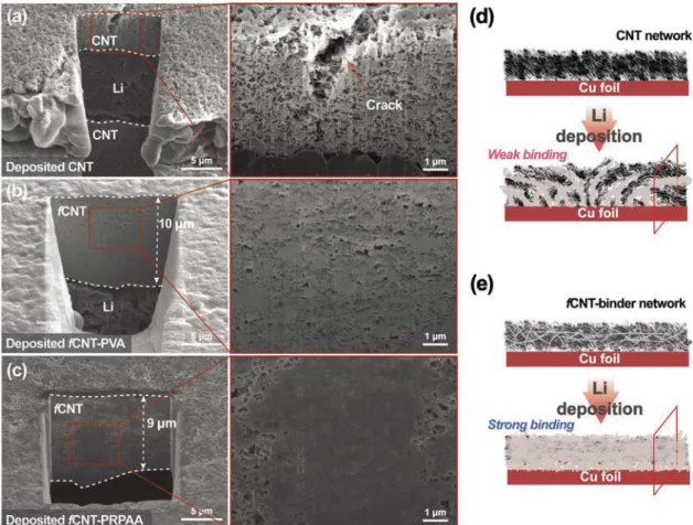
The ability of the polymeric binders in maintaining the CNT network structure during Li uptake was investigated by cross-sectional SEM analysis (Figure 2). For a bare CNT network,
Figure 1. a) Schematic illustration of structure of binders. a–d) Top view SEM images of bare CNT network (b), fCNT–PVA network (c), and fCNT–
PRPAA network (d), and e) their cross-sectional SEM images. f) XPS spectra in O 1s branches of all the CNT networks. g) Peeling force versus displace-ment profiles for all the CNT network films.
it was observed that upon Li plating with an areal capacity of 1 mAh cm–2 (3 Ah g–1
cnt), the Li dendrite growth imposed substantial stress on the CNT network (Figure 2a), eventu-ally ripping off the CNT network (the scheme in Figure 2d). Figure 2a illustrates the case where the ruptured CNT layer was loaded on the Li dendrite layer. A crack generated from the pres-sure of Li dendrites grown underneath was also observed as a result of stress propagation (see the arrow in Figure 2a). From the top-view SEM images (Figure S7, Supporting Information), the Li dendrites tore the CNT network apart because the CNT network could not absorb Li efficiently in its void space owing to the low mechanical stability of the bare CNT network.
By contrast, the Li-plated fCNT–PVA and fCNT–PRPAA networks showed a conspicuously smaller amount of Li layer between the Cu foil and the CNT network (Figure 2b,c). This result was due to the fact that after the Li was grown from the Cu foil and reached the CNT network, it was deposited more efficiently into the network. It was noted that the Li was first deposited onto Cu foil surface and then into the pores within CNT network. This observation equally means that the elec-trical contacts between the CNTs were maintained throughout the Li plating process due to the binder effect under the same stress levels exerted from the Li growth (Figure 2e). The distinct filling of Li in the CNT networks was more clearly observed in the higher magnification SEM images in Figure 2a–c. After Li
stripping, most of the internal Li was removed and the Li on the Cu foil was also stripped (Figure S8, Supporting Informa-tion). The reversible filling and removal of Li was observed in the binder-contained CNT networks in the scale of hundreds of micrometer (Figure S9, Supporting Information).
The elastic properties of the binders were revealed from stress–strain analysis. As shown in Figure 3a, while the PVA film ruptured at only 68% strain, the PRPAA film endured its film integrity up to 570% strain by taking advantage of the ring-sliding motion of the PRs. The strain recovery for many cycles was also tested since it is related to the binder’s reli-ability over repeated Li uptake–release cycles. When subjected to stretch–recovery cycling with a 50% strain limit, the PVA film recovered only 19% of the original dimension on average for 30 cycles (Figure 3b; Figure S10, Supporting Information). By contrast, even under an increased strain limit of 100%, the PRPAA film restored 60% on average for the same number of cycles (Figure 3c) due to its high elasticity. The high elasticity of PRPAA could also be observed when integrated with the CNT network. When the composite films were stretched until cracks were formed (Figure S11, Supporting Information), the fCNT– PVA network showed fairly clear disconnection of the CNTs inside the cracks, whereas the CNT network in the fCNT– PRPAA remained uninterrupted in the crack and bridged all void space.
Figure 2. a–c) Cross-sectional SEM images of bare CNT network (a), fCNT–PVA network (b), and fCNT–PRPAA network (c) after 1st Li plating.
d,e) Schematic illustration of Li plating into bare CNT network (d) and fCNT-binder network (e). Current density = 1 mA cm–2 (3 A g–1
cnt). Areal
capacity = 1 mAh cm–2 (3 Ah g–1
cnt).
Figure 3d schematically illustrates the operation mechanism of PRPAA in contrast with that of PVA during the repeated Li plating–stripping cycles. For PVA, it could not withstand the tensile stress after a certain amount of Li uptake, resulting in a rupture of the CNT network and electrical disconnection. In stark contrast, the PRPAA maintained the network integ-rity and electronic conductivity to a greater extent of Li uptake due to the high elasticity of PRPAA. The elasticity of PRPAA also made the network more robust over long-term of Li deposi-tion–extraction cycles.
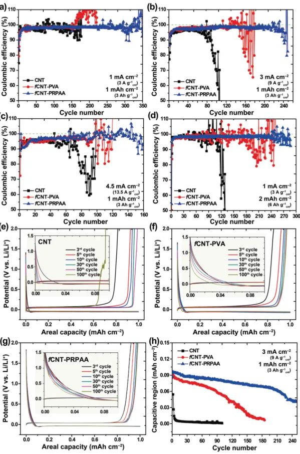
Coulombic efficiency, which is herein defined as the delithi-ation capacity over the lithidelithi-ation capacity, is considered as an indicator of plating–stripping reversibility and thus represents the degree of structural stability of a CNT network. In practical operation of a full cell, the CE value determines the amount of excess Li required in the cell design and is thus critical for the energy density of the given cell. By noting that Li dendrite growth becomes more serious with increasing current den-sity, we measured the CEs of the bare CNT, fCNT–PVA, and fCNT–PRPAA electrodes at different current densities of 1, 3,
and 4.5 mA cm–2 (corresponding to 3, 9, and 13.5 A g–1 cnt) with a fixed areal capacity of 1 mAh cm–2 (3 Ah g–1
cnt) as well as at a current density of 1 mA cm–2 (3 A g–1
cnt) with an increased areal capacity of 2 mAh cm–2 (6 Ah g–1
cnt) (Figure 4). This reversibility tests were performed in a Li–Cu asymmetric cell setting.
At a current density of 1 mA cm–2 (3 A g–1
cnt) (Figure 4a), the CEs of the bare CNT electrode began to fluctuate after around 50 cycles whereas those of the fCNT–PVA and fCNT–PRPAA electrodes fluctuated after 150 and 250 cycles, respectively. In addition, the CEs of the fCNT–PRPAA electrode remained high at 98.1% on average for 250 cycles. When the current density was increased to 3 mA cm–2 (9 A g–1
cnt) (Figure 4b), the CEs of the bare CNT electrode dropped rapidly after 80 cycles due to electrolyte depletion, whereas those of the fCNT–PVA elec-trode started to fluctuate severely at around the 140th cycle. By contrast, the fCNT–PRPAA electrode sustained the cell operation for 220 cycles, the average CE being 97.9%. A sim-ilar trend among the samples was also observed at a current density of 4.5 mA cm–2 (13.5 A g–1
cnt) (Figure 4c). In the case
Figure 3. a) Stress–strain curves of PVA and PRPAA films. b,c) Stress–strain profiles of PVA (b) and PRPAA (c) films during repeated stretch–recovery
cycles. d) Graphical presentation of CNT network configuration during lithiation and delithiation: fCNT–PVA network versus fCNT–PRPAA network.
Figure 4. a–d) Cycling performance of Li–Cu asymmetric cells with Li-metal anodes containing bare CNT network, fCNT–PVA network, and fCNT–
PRPAA network when tested with a capacity of 1 mAh cm–2 at: a) 1 mA cm–2, b) 3 mA cm–2, c) 4.5 mA cm–2, and d) with an increased capacity of
2 mAh cm–2 at 1 mA cm–2. e–g) Voltage profiles of bare CNT network (e), fCNT–PVA network (f), and fCNT–PRPAA network (g) at different cycles when
measured at 3 mA cm–2 with 1 mAh cm–2, and h) their capacity evolution related to the capacitive storage when discharged until 0 V in each cycle.
of the bare CNT electrode, the CEs started to drop sharply at around the 60th cycle, whereas the CEs of the fCNT–PVA elec-trode remained steady for 90 cycles. On the contrary, the CEs of the fCNT–PRPAA electrode stayed steady at 97.6% on average for 140 cycles. The same trend was observed when the cur-rent density was further increased to 6 mA cm–2 (18 A g–1
cnt) (Figure S12, Supporting Information). At this current density, the fCNT–PRPAA electrode still exhibited a decent average CE of 97.2% for 110 cycles.
When the areal capacity was increased to 2 mAh cm–2 (6 Ah g–1
cnt) keeping the current density fixed at 1 mA cm–2 (3 A g–1
cnt), the CEs of the bare CNT, fCNT–PVA, and fCNT– PRPAA electrodes started to drop after 100, 160, and 240 cycles, respectively (Figure 4d). In this experiment, the thickness of the networks was set to 5 μm, which corresponded to an areal capacity of approximately 1 mAh cm–2. This CNT loading was also converted to 6 Ah g–1
cnt. Thus, we evaluated the tolerance of the CNT network on overlithiation. The relatively inferior cycling performance of the bare CNT and fCNT–PVA elec-trodes at this areal capacity indicated that when the Li plating exceeded the capacity of the CNT network, the cyclability became impaired due to stress accumulation. Even under this challenging condition, the CEs of the fCNT–PRPAA electrode remained stable at 98.3% on average for 240 cycles, implying the usefulness of the elastic binder even with a substantial level of overlithiation. We exposed the fCNT–PRPAA electrode to a more challenging condition to see its operation capability under more practical cell conditions. For this purpose, the CEs of a 14 μm thick fCNT–PRPAA electrode were monitored for an areal capacity of 4 mAh cm–2 at 3 mA cm–2 (Figure S13, Sup-porting Information). This fCNT–PRPAA electrode still showed a high average CE of 97.9% for 80 cycles and stable voltage profiles, indicating that its electrochemical performance was greatly maintained. In addition, to assess the performance of the fCNT–PRPAA network with various electrolytes, we meas-ured the CEs with 1 M LiPF6 in EC/DEC (carbonate electrolyte) and 4 M LiFSI in DME (high concentrate electrolyte). In both cases, the fCNT–PRPAA network preserved superior perfor-mance compared to that of the bare CNT and fCNT–PVA net-works (Figure S14, Supporting Information).
The structural stability of the CNT networks was also reflected by the voltage profiles in the early stage of Li plating (Figure 4e–g). In the areal capacity range of 0.0–0.05 mAh cm–2 (see insets of Figure 4e–g), the voltage profiles of all the CNT electrodes gradually dropped without showing any dip, a signa-ture of Li nucleation. These voltage profiles reflected capacitive Li deposition onto the CNT networks,[17] and can thus serve as indicators of CNT connectivity because the given capacitances must be proportional to the numbers of electrically connected CNTs. When the three electrodes were compared, the fCNT– PRPAA electrode was better in maintaining the initial voltage profile in the following cycles up to the 100th cycle as com-pared to the other two electrodes. The areal capacities related to the capacitive Li deposition were plotted over cycle numbers for all of the three electrodes (Figure 4h). The better capacity retention of fCNT–PRPAA was attributed to its highly elastic and well-connected network structure during cycling, whereas in other cases the networks were ruptured and electrical con-nection lost. In this context, the more significant voltage drop
of the bare CNT electrode can be explained by the severe Li dendrite growth as observed in Figure 2a. As a control test, all the CNT electrodes were subjected to a repeated potential sweep only in the capacitive potential range of 0–2 V without Li plating (Figure S15, Supporting Information). All of the CNT electrodes retained large percentage of their initial capacities, verifying that the potential drop observed in Figure 4e–g was due to the network disconnection upon Li uptake and release.
The structural stability of the CNT networks was examined by ex situ SEM analysis after the 3 and 30 cycles (Figure 5). Since the rupture of the network was very pronounced in the bare CNT even after the 1st Li plating, we compared only fCNT–PVA and fCNT–PRPAA. The morphology of both the electrodes was monitored after 3 and 30 cycles at 3 mA cm–2 (9 A g–1
cnt) with 1 mAh cm–2 (3 Ah g–1
cnt). After 3 cycles, the fCNT–PVA elec-trode exhibited cracks through which Li dendrites penetrated from the bottom, and this dendrite penetration was far more serious compared to that of the fCNT–PRPAA counterpart. To be fair and statistically reliable, this morphology characteriza-tion was performed over an area of 0.95 cm2. The number of dendrite overgrowth spots increased after 30 cycles for both the electrodes, but such increase was far more significant in fCNT–PVA. The distinct dendrite growth was also confirmed by digital photographs of both electrodes after 30 cycles (Figure S16, Supporting Information). The thickness of the fCNT–PRPAA network was 7 μm upon Li plating of 1 mAh cm–2, and this thickness increased to 11 μm as the areal capacity was raised to 2 mAh cm–2 (Figure S17, Supporting Information). The thick-ness of the network with 2 mAh cm–2 was largely maintained over 10 cycles.
The effect of the PRPAA binder was further assessed in a full-cell configuration paired with olivine-LiFePO4 (LFP) cathode (Figure 6). The full-cell experiment was conducted with a limited amount of Li to reflect more practical cell conditions where n/p capacity ratios are restricted. To keep Li concentra-tion as a limiting condiconcentra-tion, Li foil with a thickness of 20 μm and LFP cathode with an active loading of 11.0 mg cm–2 were adopted. With this cell design, the n/p ratio, defined by total anode capacity divided by total cathode capacity, was 2.7, and this value would be decreased further once thinner Li foil is commercially available. All of the three CNT electrodes were subjected to different C-rates from 0.2C to 5C (Figure 6a). To note, although the initial capacities of all the three elec-trodes were around 147 mAh g–1
LFP when measured at 0.2C (1C = 2 mA cm–2 or 6 A g–1
cnt), the fCNT–PRPAA electrode preserved higher capacities at higher C-rates of 3C and 5C. At 5C, the bare CNT, fCNT–PVA, and fCNT–PRPAA electrodes retained 52, 64, and 77 mAh g–1
LFP, respectively, corresponding to 35%, 43%, and 52% capacity retentions with respect to the values at 0.2C. The superior rate performance of the fCNT– PRPAA electrode could be attributed to its more robust conduc-tive network that supports facile electronic transport during the sweep of various C-rates.
The impact of the PRPAA binder was also observed in the cycling performance (Figure 6b). For this galvanostatic test, the cells were cycled at 0.2C for the first two cycles and then at 1C thereafter. The bare CNT cell showed 115 mAh g–1
LFP at the 3rd cycle and the capacity decayed continuously to 69 mAh g–1
LFP at the 50th cycle, corresponding to 60% retention. By contrast,
the fCNT–PVA cell showed 126 mAh g–1
LFP at the 3rd cycle and its capacity started to decay rapidly at around the 40th cycle, seemingly a point where the Li metal on the anode began to be depleted. On the other hand, the fCNT–PRPAA cell exhib-ited 127 mAh g–1
LFP at the 3rd cycle and the capacity started
to decay after 70 cycles. Notably, even after this Li depletion point, the fCNT–PRPAA cells retained a substantial capacity of 83 mAh g–1
LFP, corresponding to 65% retention, until 140 cycles. The average CE during this cycling period was 97.9% (Figure S18, Supporting Information). These results
Figure 5. SEM images of Li-plated fCNT–PVA network and fCNT–PRPAA network after 3 and 30 cycles when measured at 3 mA cm–2 with 1 mAh cm–2.
validate the beneficial effect of the elastic binder when a limited amount of Li is present in a cell. Considering the limited freedom in the anode amount and the n/p ratio in practical cell settings, the enhanced cyclability of the fCNT–PRPAA cell sup-ports the importance of the mechanical robustness of a conduc-tive Li-hosting network.
Even though various Li-host scaffolds offer promise in dealing with the fatal issues of Li-metal anodes, the present study explic-itly demonstrated the importance of their mechanical sustaina-bility in relation to the cycle life. While a conductive network with a limited amount of CNTs suffered from rupture of the network film upon stress accumulation by repeated Li uptake and release, the incorporation of the elastic PRPAA binder largely mitigated such mechanical failures by keeping the network interconnected during cycling. In a larger context, this investigation may open up new research avenues on polymeric binders based on mechani-cally interlocked mole cules such as polyrotaxanes in emerging post-LIBs suffering from low mechanical stability.
Experimental Section
Material Synthesis: Polyethylene glycol (Mw 20 000) was purchased
from Alfa Aesar. 2,2,6,6-Tetramethyl-1-piperidinyloxy (TEMPO) radical, 1H-benzotriazol-1-yloxy-tris(dimethylamino)phosphonium hexafluorophosphate (BOP) and α-cyclodextrin were purchased from TCI chemicals. Sodium bromide (NaBr), sodium hyocholorite solution (NaClO), 1-adamantylamine (AD), carbonyldiimidazole (CDI), ethyldiisopropylamine (EDIPA) and propylene oxide (PO), poly(acrylic
acid) (Mw 450 000), and poly(vinyl alcohol) (PVA, Mw 85 000–124 000)
were purchased from Sigma Aldrich.
PRPAA was synthesized following a published procedure.[14a] The
terminal hydroxyl groups of PEG were oxidized by TEMPO to yield carboxylic acid groups. After α-CDs were threaded into the modified PEG chain, both the chain ends were capped with bulky adamantane
units. The hydroxyl groups on α-CDs were partially substituted with
2-hydroxypropyl functional groups through ring-opening reaction with PO. Finally, the PAA chains were activated through CDI, and the residual hydroxyl groups on α-CDs of PR were covalently crosslinked with the activated PAA to yield PRPAA.
In order to fabricate CNT-binder networks, CNTs (multiwalled,
D × L = 9 nm × 5 μm, Sigma Aldrich) or fCNTs (multiwalled, D × L = 9.5 nm ×
1.5 μm, >8% carboxylic acid functionalized, Sigma Aldrich) were
dispersed in ethanol at a concentration of 1 mg mL–1 via tip sonication.
The CNT dispersion (3 mL) was next filtered through a PP separator
(Celgard 2400). Then, 0.15 wt% of PVA or PRPAA solution in DMF was added to the fCNT networks in an amount corresponding to 5 wt% of the fCNT and dried under vacuum at 50 °C for 2 h. Remarkably, DMF was impermeable through the PP separator while being able to wet the fCNT network. Thus, an accurate amount of binder could be delivered into the fCNT network (Figure S19, Supporting Information). The amount of binder added to the fCNT network was optimized by performing SEM analysis for 1, 5, and 10 wt% cases (Figure S20, Supporting Information). In order to assess the tolerance against tensile stress, the fCNT-binder films loaded on a PP separator were stretched until crack was generated. The micro-morphology inside the cracks was investigated using SEM.
Cell Preparation and Electrochemical Measurements: The cathodes were
prepared based on the following procedure: commercial LiFePO4
(carbon-coated, LFP-1000, average size = 1.0 ± 0.3 μm, Hanwha chemical), super-P, and poly(vinylidenedifluoride) (PVDF) were uniformly dispersed in N-methyl 2-pyrolidone (NMP) in a weight ratio of 8:1:1. The well-mixed slurry was cast onto Al foil using the doctor blade. The cast electrodes were dried under vacuum at 80 °C for 12 h. The areal mass loading of
the active material was 11.0 mg cm–2, corresponding to an areal capacity
of 1.5 mAh cm–2 at a current density of 160 mA g–1. The electrochemical
performance was characterized by fabricating 2032 coin-type cells. Each Li–Cu asymmetric cell was comprised of a Cu foil, the separator with a 3D network, and a Li-metal anode with thickness of 300 μm (Honjo, Japan). The full cells were comprised of a Li-metal anode with diameter of 13 mm, the separator with different 3D networks, and the cathode with diameter of 12 mm. The Li-metal anode was commercially available one (Honjo,
Japan) in which 20 μm thick Li layer was coated on the Cu foil. 1 M LiTFSI
and 1 M Pyr1(4)FSI in DOL/DME was used as electrolyte as reported in
the previous study.[5d] The consistent amount of the electrolyte (50 μL)
was injected to each cell. The entire cell was assembled in an argon-filled glove box. All the electrochemical measurements were performed at
25 °C using a battery cycler (MACCOR series 4000).
Characterization: In order to characterize the synthesized polymer,
Fourier-transform infrared spectroscopy (FTIR) was recorded on a JASCO
FT/IR-6700. 1H NMR spectra were obtained using a Bruker spectrometer
(400 MHz). To measure the mechanical properties, the size of samples
prepared was 10 mm length × 10 mm width × 0.10 mm thickness.
All tests were carried out at a strain rate of 1 mm min–1. For peeling
tests, the 3M tape was attached to the top and bottom of the networks. The peeling strengths during detachment of the 3M tape and tensile stress–strain tests were recorded on a high-precision micromechanical test instrument (QM100S, QMESYS, Korea, and Autograph AG-X plus, Shimadzu, Japan), generating load-displacement plots.
For all the characterizations post electrochemical measurements, the cells were disassembled in an argon-filled glove box, and the cycled networks were washed with DME and dried under vacuum for 3 h in the glove box chamber. In order to characterize the morphology of the networks, field-emission SEM (JSM-7800F prime, JEOL, Japan) and
Figure 6. a) Rate and b) cycling performance of LFP-Li full cells with Li-metal anodes containing bare CNT network, fCNT–PVA network, and fCNT–
PRPAA network. A limited amount of Li (20 μm) was used for the anode and the mass loading of LFP was 11.0 mg cm–2.
focused ion beam (Helios 650, FEI, USA) installed at the National Center for Interuniversity Research Facilities at Seoul National University were used. The chemical compositions of the networks were analyzed by XPS (sigma probe, Thermo VG scientific, England) with an Mg K α line as an X-ray source. The binding energies were calibrated with respect to C 1s peak at 284.5 eV. For all characterizations, moisture and air contamination were avoided by using an airtight sample box during each sample transfer.
Supporting Information
Supporting Information is available
Acknowledgements
D.-J.Y., A.E., and S.C. contributed equally to this work. The authors acknowledge financial support from a National Research Foundation of Korea grant (NRF-2018R1A2A1A19023146 and NRF-2018M1A2A2063340).
Conflict of Interest
The authors declare no conflict of interest.
Keywords
carbon nanotube networks, elastic binders, lithium-metal anodes, molecular machines, polyrotaxane
[1] a) J. W. Choi, D. Aurbach, Nat. Rev. Mater. 2016, 1, 16013; b) B. Dunn, H. Kamath, J.-M. Tarascon, Science 2011, 334, 928. [2] a) X. Liang, Q. Pang, I. R. Kochetkov, M. S. Sempere, H. Huang,
X. Sun, L. F. Nazar, Nat. Energy 2017, 2, 17119; b) C. Liu, F. Li, L. P. Ma, H. M. Cheng, Adv. Mater. 2010, 22, E28; c) W. Xu, J. Wang, F. Ding, X. Chen, E. Nasybulin, Y. Zhang, J.-G. Zhang, Energy
Environ. Sci. 2014, 7, 513.
[3] a) Y. Gao, Y. Zhao, Y. C. Li, Q. Huang, T. E. Mallouk, D. Wang,
J. Am. Chem. Soc. 2017, 139, 15288; b) J.-S. Kim, D. W. Kim,
H. T. Jung, J. W. Choi, Chem. Mater. 2015, 27, 2780; c) H. Lee, X. Ren, C. Niu, L. Yu, M. H. Engelhard, I. Cho, M. H. Ryou, H. S. Jin, H. T. Kim, J. Liu, Adv. Funct. Mater. 2017, 27, 1704391; d) N. W. Li, Y. X. Yin, C. P. Yang, Y. G. Guo, Adv. Mater. 2016, 28, 1853; e) Z. Tu, S. Choudhury, M. J. Zachman, S. Wei, K. Zhang, L. F. Kourkoutis, L. A. Archer, Joule 2017, 1, 394; f) J. Zhao, L. Liao, F. Shi, T. Lei, G. Chen, A. Pei, J. Sun, K. Yan, G. Zhou, J. Xie, J. Am. Chem. Soc.
2017, 139, 11550.
[4] a) K. Yan, Z. Lu, H.-W. Lee, F. Xiong, P.-C. Hsu, Y. Li, J. Zhao, S. Chu, Y. Cui, Nat. Energy 2016, 1, 16010; b) C. Yang, Y. Yao, S. He, H. Xie, E. Hitz, L. Hu, Adv. Mater. 2017, 29, 1702714.
[5] a) S. Jurng, Z. L. Brown, J. Kim, B. L. Lucht, Energy Environ. Sci.
2018, 11, 2600; b) W. Li, H. Yao, K. Yan, G. Zheng, Z. Liang,
Y.-M. Chiang, Y. Cui, Nat. Commun. 2015, 6, 7436; c) X. Li, J. Zheng, X. Ren, M. H. Engelhard, W. Zhao, Q. Li, J. G. Zhang, W. Xu, Adv.
Energy Mater. 2018, 8, 1703022; d) D. J. Yoo, K. J. Kim, J. W. Choi, Adv. Energy Mater. 2018, 8, 1702744.
[6] a) J. Alvarado, M. A. Schroeder, T. P. Pollard, X. Wang, J. Z. Lee, M. Zhang, T. Wynn, M. Ding, O. A. Borodin, S. Meng, K. Xu, Energy
Environ. Sci. 2019, 12, 780; b) X. Fan, L. Chen, X. Ji, T. Deng, S. Hou,
J. Chen, J. Zheng, F. Wang, J. Jiang, K. Xu, Chem. 2018, 4, 174; c) J. Qian, W. A. Henderson, W. Xu, P. Bhattacharya, M. Engelhard, O. Borodin, J.-G. Zhang, Nat. Commun. 2015, 6, 6362; d) L. Suo, Y.-S. Hu, H. Li, M. Armand, L. Chen, Nat. Commun. 2013, 4, 1481; e) D. J. Yoo, S. Yang, Y. S. Yun, J. H. Choi, D. Yoo, K. J. Kim, J. W. Choi, Adv. Energy Mater. 2018, 8, 1802365.
[7] a) H. Duan, M. Fan, W. P. Chen, J. Y. Li, P. F. Wang, W. P. Wang, J. L. Shi, Y. X. Yin, L. J. Wan, Y. G. Guo, Adv. Mater. 2019, 1807789; b) J. Duan, W. Wu, A. M. Nolan, T. Wang, J. Wen, C. Hu, Y. Mo, W. Luo, Y. Huang, Adv. Mater. 2019, 1807243; c) X. Fan, X. Ji, F. Han, J. Yue, J. Chen, L. Chen, T. Deng, J. Jiang, C. Wang, Sci. Adv.
2018, 4, eaau9245; d) K. K. Fu, Y. Gong, G. T. Hitz, D. W. McOwen,
Y. Li, S. Xu, Y. Wen, L. Zhang, C. Wang, G. Pastel, Energy Environ.
Sci. 2017, 10, 1568; e) W. Luo, Y. Gong, Y. Zhu, Y. Li, Y. Yao,
Y. Zhang, K. Fu, G. Pastel, C. F. Lin, Y. Mo, Adv. Mater. 2017, 29, 1606042; f) C. Wang, Y. Gong, J. Dai, L. Zhang, H. Xie, G. Pastel, B. Liu, E. Wachsman, H. Wang, L. Hu, J. Am. Chem. Soc. 2017, 139, 14257.
[8] X.-X. Zeng, Y.-X. Yin, Y. Shi, X.-D. Zhang, H.-R. Yao, R. Wen, X.-W. Wu, Y.-G. Guo, Chem 2018, 4, 298.
[9] a) C. Brissot, M. Rosso, J.-N. Chazalviel, S. Lascaud, J. Power
Sources 1999, 81, 925; b) Q. Pang, X. Liang, A. Shyamsunder,
L. F. Nazar, Joule 2017, 1, 871.
[10] a) G. Li, Z. Liu, Q. Huang, Y. Gao, M. Regula, D. Wang, L.-Q. Chen, D. Wang, Nat. Energy 2018, 3, 1076; b) G. Yang, Y. Li, Y. Tong, J. Qiu, S. Liu, S. Zhang, Z. Guan, B. Xu, Z. Wang, L. Chen, Nano
Lett. 2018, 19, 494.
[11] L. Liu, Y. X. Yin, J. Y. Li, S. H. Wang, Y. G. Guo, L. J. Wan, Adv. Mater.
2018, 30, 1706216.
[12] a) S. Huang, W. Zhang, H. Ming, G. Cao, L.-Z. Fan, H. Zhang,
Nano Lett. 2019, 19, 1832; b) H. Lee, J. Song, Y.-J. Kim, J.-K. Park,
H.-T. Kim, Sci. Rep. 2016, 6, 30830; c) D. Lin, Y. Liu, Z. Liang, H.-W. Lee, J. Sun, H. Wang, K. Yan, J. Xie, Y. Cui, Nat. Nanotechnol.
2016, 11, 626; d) L.-L. Lu, J. Ge, J.-N. Yang, S.-M. Chen, H.-B. Yao,
F. Zhou, S.-H. Yu, Nano Lett. 2016, 16, 4431; e) A.-R. O. Raji, R. Villegas Salvatierra, N. D. Kim, X. Fan, Y. Li, G. A. Silva, J. Sha, J. M. Tour, ACS Nano 2017, 11, 6362; f) M. Wang, Z. Peng, W. Luo, F. Ren, Z. Li, Q. Zhang, H. He, C. Ouyang, D. Wang,
Adv. Energy Mater. 2019, 1802912; g) G. Xu, A. Kushima, J. Yuan,
H. Dou, W. Xue, X. Zhang, X. Yan, J. Li, Energy Environ. Sci. 2017,
10, 2544; h) D. Zhang, Y. Yin, C. Liu, S. Fan, Chem. Commun. 2015, 51, 322; i) R. Zhang, X. Chen, X. Shen, X.-Q. Zhang, X.-R. Chen,
X.-B. Cheng, C. Yan, C.-Z. Zhao, Q. Zhang, Joule 2018, 2, 764; j) R. Zhang, X. B. Cheng, C. Z. Zhao, H. J. Peng, J. L. Shi, J. Q. Huang, J. Wang, F. Wei, Q. Zhang, Adv. Mater. 2016, 28, 2155; k) Y. Zhao, Y. Ye, F. Wu, Y. Li, L. Li, R. Chen, Adv. Mater. 2019, 1806532. [13] a) J. Li, P. C. Ma, W. S. Chow, C. K. To, B. Z. Tang, J. K. Kim, Adv.
Funct. Mater. 2007, 17, 3207; b) P. C. Watts, W.-K. Hsu, H. W. Kroto,
D. R. Walton, Nano Lett. 2003, 3, 549.
[14] a) S. Choi, T.-w. Kwon, A. Coskun, J. W. Choi, Science 2017, 357, 279; b) T.-w. Kwon, J. W. Choi, A. Coskun, Joule 2019, 2, 950.
[15] a) A. B. Imran, K. Esaki, H. Gotoh, T. Seki, K. Ito, Y. Sakai, Y. Takeoka, Nat. Commun. 2014, 5, 5124; b) Y. Okumura, K. Ito,
Adv. Mater. 2001, 13, 485.
[16] a) J. H. Lee, H. J. Lee, J. W. Choi, Phys. Chem. Chem. Phys. 2017,
19, 22743; b) L. Tang, X. Li, R. Ji, K. S. Teng, G. Tai, J. Ye, C. Wei,
S. P. Lau, J. Mater. Chem. 2012, 22, 5676.
[17] J. Lin, C. Zhang, Z. Yan, Y. Zhu, Z. Peng, R. H. Hauge, D. Natelson, J. M. Tour, Nano Lett. 2012, 13, 72.