A DESIGN TOOL FOR THE EVALUATION OF ATMOSPHERE INDEPENDENT PROPULSION IN SUBMARINES
by
Grant B. Thomton, LCDR, USN
B.S., Marine Engineering United States Naval Academy, 1979
SUBMITTED TO THE DEPARTMENTS OF OCEAN ENGINEERING AND MECHANICAL ENGINEERING IN PARTIAL FULFILMENT
OF THE REQUIREMENTS FOR THE DEGREES OF
MASTER OF SCIENCE IN NAVAL ARCHITECTURE AND MARINE ENGINEERING
and
MASTER OF SCIENCE IN MECHANICAL ENGINEERING
at the
MASSACHUSETTS INSTITUTE OF TECHNOLOGY
May 1994
Copyright © 1994 Grant B. Thomton
The author hereby grants to MIT permission to reproduce and to distribute publicly paper and electronic copies of this thesis document in whole or in part.
Signature of Author . ... .
-.,/../ ~-u-_:.-.;Departments of Ocean and Mechanical Engineering
May 6, 1994
Certified by
Professor David Gordon Wilson Thesis Reader -. Department of Mechanical Engineering
Accepted b!y
"---' Prfess A. Douglas Carmichael
Thesis Advisor and Chairma0, Jepartment Committee on Graduate Students ,W1IT ;.- ;,: ^.-- . Department of Ocean Engineering
A DESIGN TOOL FOR THE EVALUATION OF ATMOSPHERE
INDEPENDENT PROPULSION IN SUBMARINES by
Grant Blount Thornton
Submitted to the Departments of Ocean Engineering and Mechanical Engineering on May 6, 1994 in partial fulfilment of the requirements
for the Degrees of Master of Science in Naval Architecture and Marine Engineering and Master of Science in Mechanical Engineering. ABSTRACT
For the United States Navy, submarine propulsion has long since evolved from Diesel Electric to a complete reliance on Nuclear Power. Nuclear propulsion is the ultimate atmosphere independent power source, allowing the submarine to divorce itself from the surface, limited only by the endurance of the crew embarked.
Submarine construction and operating costs have grown dramatically, due largely to the cost of the high performance nuclear propulsion plant. Other options exist to provide Atmosphere Independent Propulsion of similar capability for extended underwater periods at a potentially lower cost.
This thesis explores the aspects of non-nuclear atmosphere independent propulsion as an integral part of the submarine design process, focusing on methods for power generation and various options for fuel and oxidant storage.
Fuel sources include pure hydrogen, stored cryogenically or in metal hydrides, or more common fuels such as diesel or methanol, used either directly or in a reformed state. Oxidants include pure oxygen, stored cryogenically or in compressed form, as well as hydrogen peroxide and sodium perchlorate. Energy conversion methods examined include mechanical such as closed cycle diesels, Brayton cycles and Stirling engines, to electro-chemical designs, such as fuel cells and aluminum oxygen semi-cells.
A computer code was written which integrates these propulsion options with mission and owner's requirements to provide a balanced design in terms of matching the weights and volumes of the equipment installed. This code will serve as a tool for the concept design of non-nuclear air independent submarines.
Thesis Supervisor: A. Douglas Carmichael, Professor of Ocean Engineering
ACKNOWLEDGEMENTS
I wish
for reference
to acknowledge the following persons who aided me in my search material: Dave Bagley Mark Cervi Henry DeRonck LCDR Norbert Doerry Richard Martin Warren Reid Ed Robinson Steve Sinsabaugh LT Cliff Whitcomb
I hope that I have correctly available to me.
NSWC Annapolis NSWC Annapolis International Fuel Cells NAVSEA
Draper Laboratory NSWC Annapolis NAVSEA PEO SUB-R LORAL Defense Industries NSWC Carderock
interpreted the information that you made
I am grateful for the counsel in ship and submarine design provided by Professors Alan Brown and Jeff Reed in the Naval Construction and Engineering
Program at MIT.
I wish to thank my Thesis Advisor, Professor A. D. Carmichael who inspired me to investigate the realm of Air Independent Propulsion as a student,
who stood by me as I worked to put my research together in an orderly fashion,
and who taught me to be aware of the salesman and the customer when evaluating data.
But most of all, I am thankful for the love and understanding of my family;
TABLE OF CONTENTS ABSTRACT ACKNOWLEDGEMENTS TABLE OF CONTENTS LIST OF FIGURES . LIST OF TABLES CHAPTER ONE 1.0 Introduction 1.1 History
1.2 Air Independence Concept
1.3 Propulsion Options 1.4 Thesis Objective CHAPTER TWO
2.0 The Design Process
2.1 Mission Requirements.
2.2 Required Operational Capabilities
2.3 Submarine Hull Synthesis CHAPTER THREE 3.0 Submarine Systems 3.1 Propulsion Integration . 3.1.1 Conventional DC 3.1.2 Permanent Magnet AC 3.1.3 Superconducting Homopolar DC 3.1.4 Propulsors
3.2 Ship Service Power Requirements
3.3 Auxiliary Systems 3.4 Atmosphere Control CHAPTER FOUR 4.0 Power Sources . 4.1 Electro-Chemical Concepts 4.1.1 Fuel Cells
4.1.1.1 Proton Exch. Membrane Fuel Cells
4.1.1.2 Alkaline Fuel Cells
4.1.1.3 Phosphoric Acid Fuel Cells 4.1.1.4 Molten Carbonate Fuel Cell 4.1.1.5 Solid Oxide Fuel Cell
4.1.1.6 Direct Methanol Oxidation Fuel Cell
4.1.2 Aluminum Oxygen Semi-Cell 4.1.3 Batteries
4.1.3.1 Lead Acid Batteries
4.1 .3.2 Nickel-Cadmium Batteries 3 5 7 13 17 19 19 20 21 21 25 27 29 33 37 38 38 40 42 44 44 46 46 51 52 52 54 57 57 58 60 60 62 64 65 68
4.1.3.3 Silver-Zinc . .70 4.1.3.4 Lithium-Aliminum / Iron Sulfide 72
4.2 Mechanical Power Sources 74
4.2.1 Closed Cycle Engines 74
4.2.1.1 Closed Cycle Diesel 74
4.2.1.2 Closed Brayton Cycle 77
4.2.2 Stirling Engine 79
4.2.3 Other Power Cycles. . . . 80
4.2.3.1 Rankine Cycle 81
4.2.3.2 Small Nuclear Power 83
4.2.3.3 Walter Cycle 83
CHAPTER FIVE
5.0 Reactants 87
5.1 Fuels 88
5.1.1 Hydrogen 88
5.1.1.1 Hydrogen - Gaseous Storage 89 5.1.1.2 Hydrogen - Cryogenic Storage 89
5.1.1.3 Hydrogen - Metal Hydride 90
5.1.1.4 Hydrogen - By Reformation 92
5.1.2 Other Fuels 94
5.2 Oxidants. 95
5.2.1 Oxygen 95
5.2.1.1 Oxygen - Gaseous Storage 95
5.2.1.2 Oxygen - Cryogenic Storage 96 5.2.1.3 Oxygen - Chemical Reformation. 98 5.2.1.4 Oxygen - Generation Onboard . 99
5.2.2 High Test Hydrogen Peroxide 99
5.3 Waste Products 101
CHAPTER SIX
6.0 The Submarine Model. 105
6.1 Hull Envelope . 106
6.2 Volume Estimates 107
6.2.1 Pressure Hull Volume 107
6.2.1.1 Mobility Volume 107
6.2.1.2 Weapons and C31 Volume 108
6.2.1.3 Ship Support Volume 108
6.2.2 Other Volumes 109
6.3 Weight Estimates 110
6.3.1 Surfaced Displacement 111
6.3.1.1 Structural Weight . 111
6.3.1.2 Mobility Weight 111
6.3.1.3 Weapons and C31 Weight 112
6.3.1.4 Ship Support Weight 112
6.4 Powering and Edurance
6.4.1 Powering
6.4.1.1 Hydrodynamics
6.4.1.2 Propulsion Motor Turndown
6.4.2 Snort Power and Bunker Fuel Calculation
6.4.3 Hotel Loads
6.4.4 Battery Endurance 6.5 The AIP Plant
CHAPTER SEVEN
7.0 Computer Code Development
7.1 Overview
CHAPTER EIGHT
8.0 Results and Conclusions 8.1 Model Validation
8.2 General Results
8.2.1 Overall AIP Impact
8.2.2 Impact of Reactants .
8.2.3 Impact of Other Technologies 8.3 Ship Trade-offs.
CHAPTER NINE
9.0 Areas for Future Study
REFERENCES APPENDIX A APPENDIX B APPENDIX C APPENDIX D APPENDIX E APPENDIX F APPENDIX G APPENDIX H
- POWER SOURCE DOCUMENTATION - REACTANT DOCUMENTATION
- BASELINE MODEL
-HULL ENVELOPE
-VOLUME DATA BASE
-WEIGHT DATA BASE - SNORKEL POWERING - RESULT DATA TABLES. APPENDIX I - COMPUTER CODE
114 114 114 117 117 118 119 120 121 121 125 125 127 128 130 132 135 139 141 147 163 175 191 195 201 205 207 211
LIST OF FIGURES
2.1 Acquisition Milestones and Phases 26
2.2 The Design Spiral . 27
2.3 Balancing Weights and Volumes . 35
3.1 Battery Stepping Operating Modes for a Double Armature DC Mtr 39
3.2 Permanent Magnet Axial Gap Propulsion Motor 40
3.3 Permanent Magnet High Speed Generator 41
3.4 Example of Chopped AC Output from Input DC. 42
3.5 Superconducting Homopolar DC Motor . 43
3.6 Typical Ship Service Distribution System 45
3.7 Hydraulic System with Typical Loads 47
3.8 High Pressure Air System . 47
3.9 Ventilation Arrangement 49
4.1 Efficiency vs. Load for AIP Options 53
4.2 Proton Exchange Membrane Fuel Cell 55
4.3 PEM Cell Voltage vs. Cell Load 56
4.4 Molten Carbonate Fuel Cell 59
4.5 Westinghouse Solid Oxide Fuel Cell 61
4.6 Aluminum Oxygen Semi-Cell 63
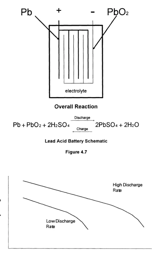
4.7 Lead Acid Battery Schematic 67
4.8 Typical Lead Acid Discharge Characteristics 67
4.9 Nickel-Cadmium Discharge Characteristics 70
4.10 Silver Zinc Discharge Characteristics 72
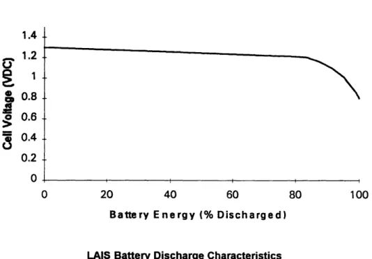
4.11 LAIS Battery Discharge Characteristics . 74
4.12 Closed Cycle Diesel with Exhaust Management System 76
4.13 Closed Brayton Cycle Combustion Power System 78
4.14 Closed Brayton Cycle Schematic Flow Diagram 79
4.15 Stirling Operating Cycle 81
4.16 MESMA Operating Cycle . 82
4.17 AMPS Power Cycle. . . . 84
4.18 Walter Power Cycle. 85
5.1 Metal Hydride Storage in Ex-U1 (German Type 205) . 91
5.2 Hydrogen Content of Various Fuels 94
5.3 Torroidal Gaseous Oxygen Storage Concept 96
5.4 44 Inch UUV Oxygen Supply Concept 98
5.5 Comparison of Oxidant Storage Methods 100
5.6 Liquid / Gas Flow Mixer . . . 102
5.7 Cosworth Exhaust Management System. 103
6.1 The Submarine Envelope .
...
1068.1 Comparison of Canadian Hybrid Submarine and SUBSIZE Results 126
8.2 Comparison of AIP Plants . 129
8.3 AIP Plant Variation with Endurance 129
8.4 Comparison of Oxidant Storage Methods 131
8.5 Comparison of Hydrogen Storage Methods 131
8.6 Comparison of Battery Options with Fixed Creep Endur. Reqm't 132
8.7 Comparison of Battery Options with Fixed Burst Endur. Reqm't 133
8.8 Effect of Propulsive Coefficient on NSC . 134
8.9 Effect of L/D Ratio on NSC and SHP 135
8.10 Effect of AIP Speed on NSC 136
A. 1 Ni/Cd vs. Discharge Rate . 160
B. 1 Liquid Oxygen Tank Arrangement 167
C.1 Profile View of Baseline Submarine 176
C.2 Chart of Propeller Efficiency 178
D.1 The Body of Revolution Hull 192
D.2 Effects of na and nfon Hull Geometry 193
E.1 Mobility Density 197
E.2 Torpedo Tube and Reload Density 197
LIST OF TABLES
1.1 AIP Power Source and Reactant Options . . . 22
2.1 Comparison of AlP/Conventional Submarines . 30
2.2 Statement of Requirements 32
2.3 Design Philosophy . 33
3.1 Propulsion Options . 38
4.1 Electro-Chemical AIP Concepts . 52
4.2 Summary of Battery Types. 65
4.3 Mechanical AIP Concepts . 75
5.1 AIP Reactant Options 87
8.1 Comparison of AIP Plant Densities 127
8.2 Effect of Propulsion Motor Type on NSC. 134
8.3 Indiscretion Ratio and Speed of Advance 137
A. 1 Summary of Energy Conversion Devices 148
B.1 Reactant Packing Factors . 164
C.1 Baseline Submarine Summary 177
C.2 Summary of Propeller Characteristics 177
C.3 Propeller Selection Spreadsheet . 179
D.1 Selected Values for Cp and Csf . 193
E. 1 Summary of Volume Data . 196
CHAPTER ONE
1.0 INTRODUCTION
1.1 HISTORY
The submarine, a dramatic addition to any country's naval arsenal, is well documented throughout history. With modest beginnings as early as the Turtle in the Revolutionary War [11], the importance of the submarine has grown as technology has enabled the ship to develop greater agility and endurance in its operations. Submersible boats, powered by diesel electric propulsion plants on the surface and lead acid storage batteries submerged, were first used extensively in combat during World War I by the German Navy where they were very effective in sinking considerable military and civilian shipping in an attempt to isolate England and her allies from the United States.
World War II brought more advanced ships into combat with similar tactics as these ships were still not true submersibles. With a hull design more akin to performance on the surface, these were still ships that operated largely on the surface of the sea, only to submerge for their torpedo attack. Though the Germans worked feverishly on developing new technologies to enable the submarine to stay submerged longer, such as the snorkel and an air independent power plant: the Walter Cycle, a carbon dioxide-steam Rankine cycle powered by high test hydrogen peroxide [46], they were eventually overcome by Allied tactics and superior strength. The United States submarine force was also successful in their campaigns against the Japanese Empire. Instrumental in holding the Japanese in check while the United States recovered from the attack on Pearl Harbor, their heroic actions against military and merchant shipping were critical to defeating the Japanese. Still the submarine
was a "surface ship" that dived to attack, and was limited in its ability to obtain air from above to sustain propulsion beyond slow speeds on battery power.
The advent of nuclear power in the late 1950's brought a significant shift in submarine design and use. With a power source that was truly divorced from the surface, an emphasis was placed on underwater performance. Submarine hull shapes similar to the now familiar tear drop "Albacore Hull" became commonplace and tactics, sensors and weapons evolved that were designed to be employed with the ship underwater. The price of nuclear power however is not cheap. Not only was the cost of development expensive, but the necessary infrastructure to build, maintain and train such a force limited its acceptance to only a few nations with the necessary financial resources. This meant that those countries that wished to continue to develop their own submarine fleets must work on improving the "diesel boat" design.
1.2 AIR INDEPENDENCE CONCEPT
While submarine improvements can take many forms, this thesis will concentrate on those which enhance propulsion endurance.
The concept of Air Independent Propulsion (AIP) can be defined many ways, but will be taken here to mean propulsive power that is generated without inducting an oxidant, air, from the atmosphere. Modern diesel electric submarines seek to improve the amount of time that they can divorce from the surface, which is accomplished by increasing the storage capacity of installed secondary batteries and by decreasing the required submerged electrical load through more power efficient equipment and reduced electric propulsion loads (more efficient hull designs and propulsors). Modern diesel electric submarines extend this time to many hours but usually at the expense of limiting the
concept that may enhance the performance of this capable diesel submarine platform by extending this submerged endurance to many weeks, without severely hampering the ship or the crew.
1.3 PROPULSION OPTIONS
Imagine any way to store any form of energy and to convert that stored energy to electricity or mechanical work and you have a potential AIP source. These ideas however must be tempered by common sense and the bounds of what could conceivably placed in the hull of a submarine. Table 1.1 presents a list of possible AIP power systems that have been proposed or developed, divided into two areas: Power Sources and Reactants. All power sources must consume some combination of reactants, usually a fuel and an oxidant to provide power output. While nuclear power is considered the ultimate AIP source due to its infinite (relative to any mission requirement) stored energy capacity, only non-nuclear AIP sources will be considered in this thesis.
1.4 THESIS OBJECTIVE
Many nations desire the goal of unrestricted submarine operations, but are unable or unwilling to make the step to nuclear power. Even the United States, a world leader in safe and reliable nuclear propulsion may have cause to consider returning to a mix of nuclear and non-nuclear submarines to perform its assigned missions world-wide. The question becomes which one of the possible AIP systems to choose and what will its impact be?
This thesis attempts to answer that question by development of a computer model in "C++" to integrate the submarine design process with the various propulsion plant options and reactant storage methods,
Table 1.1
AIP Power Source and Reactant Options
Power Sources (Electro-Chemical Remarks
Proton Exchange Membrane Fuel Cell Most promising H.-O cell
Alkaline Fuel Cell Proven design
Phosphoric Acid Cell Proven design, low interest
Molten Carbonate Fuel Cell Mature commercial applications Solid Oxide Fuel Cell Immature, highest projected efficiency Aluminum Oxygen Semi-Cell Competitive with PEM cell
Lead Acid Battery Proven performance
Nickel Cadmium Battery Higher power density than lead acid Lithium-Aluminum/Iron Sulfide Battery Potential successor to lead acid
Power Sources (Mechanical)
Closed Cycle Diesel Mature, lowest cost system
Stirling Engines Mature, low power only
Closed Brayton Cycles Excellent potential for development
Rankine Cycles Proven technology
Walter Cycles Safety of HO,
Reactants (Fuel)
Hydrogen Pure source, "hard to store"
Hydrocarbon Based Fuels With reformer-"best" hydrogen source
Reactants (Oxidants)
Oxygen Cryogenics best method
Hydrogen Peroxide Potentially unstable if concentrated
including consideration of owners requirements for ship performance. The model will allow a user to input various performance criteria such as range, maximum speed, AIP endurance, select a type of AIP power plant and form of reactant, and develop a balanced estimate of the required submarine size, in terms of its principal dimensions as well as other submarine attributes such as displacement, reserve buoyancy and lead margins. For the propulsion plant and reactant options, the field was limited to those options which are currently in development or which have had development work attempted, although other options are mentioned.
CHAPTER TWO
2.0 THE DESIGN PROCESS
The ship procurement process is long and complex, employing many different strategies and methods to achieve a final product that meets the needs of the customer in terms of performance and cost. While there are as many different ways to approach this problem as there are countries that attempt it, they all share a common approach in that they:
- Identify requirements which result in a need for a ship - Determine required capabilities
- Examine alternatives on paper
- Trade-off these alternatives using self imposed priorities - Select a concept on which to do detailed design
- Construct the ship and measure its performance - Evaluate the ship's success in terms of meeting stated
requirements
The United States Navy has adopted the format illustrated in Figure 2.1 for this acquisition process. Each milestone represents a decision point where the work from the previous phase is evaluated, and if appropriate a decision made to proceed, with requirements established for the next phase. Each phase represents a process where options are evaluated, and trade-off decisions made to achieve the required level of detail for that design. This thesis supports "Phase 0", the concept design phase of the design process.
Given the operational requirements set out by the owner, concepts to meet these requirments are explored, then for the most viable concepts, estimates are made of the required volume and weight for a ship meeting these
Acquisition Milestones and Phases
Figure 2.1 [9]
requirements and a ship is synthesized, including the buoyancy and balance requirements unique to submarine design. This balancing process is iterative and can be best visualized as a spiral, Figure 2.2. Because a successful design is the result of the efforts of many individual expert teams, each will focus on the current set of requirements, evaluating their impact on each other once all have completed their calculations. From these results, revised requirements are established and each team refines their estimates, each time obtaining a solution more in harmony with the others.
Section 2.1 describes the mission requirements for AlP submarines, one of the key inputs to the development of a concept design. Section 2.2 addresses the process of establishing priorities among the required capabilities established, while Section 2.3 provides an overview of the process required for submarine hull synthesis.
Preliminary Sizing
Arrangements
The Design Spiral [34] Figure 2.2
2.1 MISSION REQUIREMENTS
What performance characteristics should an AIP submarine possess? Clearly the evolution from diesel to nuclear power brought an increase in the ability of the submarine to transit from station to station quickly and covertly, remaining submerged for weeks on end. Aside from this step increase in performance, other improvements in hull and propulsor design have stretched the envelope even further. How many of these and other improvements can be applied to AIP submarine design, and what can the expected performance results be? It will be shown that while an AIP power plant can significantly
improve the performance of a conventional submarine when compared to a nuclear powered submarine, the current state of AIP technology places limits on key parameters such as patrol speed, burst speed, and submerged endurance.
When the United States committed itself to an all nuclear submarine force, it adopted the philosophy that these ships should be multi-mission capable. The LOS ANGLES class submarine exemplifies this mind set. Built for speed, this class of submarine was enhanced to improve its ability to keep pace with, and support a high speed carrier battle group, while maintaining the tools necessary to perform other submarine missions. The addition of vertical launch cruise missiles to the LOS ANGLES class has added yet another dimension to this formidable platform. Estimated SEAWOLF capabilities echo this
commitment to a multi-mission platform.
It can be argued that the United States possesses the only true "blue water" navy in the world, and perhaps the only one requiring a sustained, high speed capability. Most nations with submarines are concerned with defense of their home waters, and have designed their navies accordingly. For example, Sweden's submarines operate in the Baltic Sea which is nominally 200 nautical miles (nm) wide with a maximum transit distance to patrol of 1000 nm. As a result, Sweden has incorporated a low power (2-75 kW Stirling Engines) AIP power plant in their submarine NAECKEN [20]. Canada has expressed interest in a long range AIP capability for its next generation diesel submarine to enable her to control the vast ocean basin underneath the Arctic ice cap, while Australia requires a similar long range capability of 9,000 nm to patrol and defend her expansive coastline [67, 68].
Missions compatible with the role of the submarine in the U S Navy include:
- Peacetime Engagement (show the flag)
- Surveillance - Deterrence
- Regional Sea Denial - Precision Strike Warfare - Ground Warfare Support
- Unrestricted Submarine Warfare [62]
All of these missions can be performed by an AIP capable submarine.
Table 2.1 summarizes the operational capabilities of several classes of conventional and AIP capable submarines. Included in the table are designs already in service, as well as several designs not yet proven at sea. The operational characteristics of a LOS ANGELES class submarine are included for comparison to illustrate the impact of nuclear power on submarine design. As can be seen, many nations have settled on designs that are significantly smaller than the LOS ANGLES class submarine. It is also interesting to note that the conventional designs all have similar, albeit less capable operational characteristics, indicating the current limits placed on submarine design by AIP
and/or diesel technology.
2.2 REQUIRED OPERATIONAL CAPABILITIES
In developing the actual concept design for a submarine, the "owner" or sponsor for the ship must specify what requirements the ship must meet to be considered an acceptable design. From the Milestone 0 approval for example, specific capabilities would be matched to the required missions for the submarine, Section 2.1 above, such as:
Table 2.1
Comparison of AlP/Conventional Submarines
a. Janes Fighting Ships 1990-91, Capt. Richard Sharpe OBE RN ed., London, England.
b. Stennard, J. K, Comparative Naval Architecture of Modem Foreign Submannes, Thesis, Ocean Engineering Department, Massachusetts Institute of Technology, May 1988.
c. Anon., The WALRUS Launched-First of a New Class of Dutch SSK., The NavalArchitect, Royal Institute of Naval Architects, London, England, January 1986.
d. Anon., Maritime Defence. Volume 8, Number 4, April 1983.
e. Anon., The Kockums Group, Advertising Supplement to Janes Defense Weekly, March 1994.
f. Australian Collins Class Submarine Takes Shape, The Naval Architect, Royal Institute of Naval Architects, London, England, February 1993.
g. The A19 and Type 471 Submarines from Kockums, The Naval Architect, Royal Institute of Naval Architects, London, England, May 1991.
Los Angeles Kilo Walrus Type 2400 Type 1700 Naecken Collins Country US USSR Netherlands UK FGR Sweden Australia
(Info. Source) a a b c b d a e,f
Year in 1976 1980 1985 1986 1984 1980 1994
Service
Submerged 6,927 Ron 3,000 Iton 2,800 Iton 2400 Iton 2,350 Iton 1,085 Iton 2,450 Iton
Displacement 3,000(AIP)
Length 360 f 239.5 ft 223.1 f 230.6 ft 216.5 ft 182.1 ft 249.3 ft
Diameter 33 ft 31.2 It 27.6 ft 25 ft 23.9 ft 18 ft 26.2 ft
Diving Depth 1475 ft 1000 ft > 1000 ft >660 ft > It 1000 1000 f > 1000 ft
Max. Subm. >30 knots 17 knots 20 knots 20 knots 25 knots 20 knots 20 knots
Speed
Shaft 35,000 hp 6,000 hp 6,900 hp 5,360 hp 6,600 hp 1,800 hp 6,000 hp Horsepower
AIP Power Y N N N N Y Planned
Source Nuclear Stirling PEM/Stirling
Mission 90 days 45 days 70 days 49 days 70 days ??? ??? days Length
Complement 133 men 45 men 50 men 44 men 35 men 19 men 42 men Range Unlimited 9600 nm 10,000 nm 7,056 nm 10,000 nm ??? 9,000 nm
Torpedo 4 6 4 6 6 8 6
Tubes
Torpedo 22 18 24 12 20 12 ??
Reloads
Cruise Missile Y Y Y Y Y Y Y / Y N / Y N/Y Y Y
Mission Capability
Surveillance Coastline and Open Ocean monitoring, Drug Interdiction
Ground Warfare Seal Team Insertion and Recovery
Strike Warfare Launch Cruise Missiles against land targets
In meeting these capabilities, operational performance parameters will be specified to give the naval architect measurable attributes upon which to base the design. This "Statement of Requirements" will also provide a range of acceptable values, from a "Goal" or optimum value for that characteristic to a "Threshold" or minimum acceptable value. A ship that does not at least meet all the threshold values established by the owner will generally not be accepted. The range of values specified for each requirement provide the latitude necessary for trading off capabilities. Table 2.2 illustrates a typical Statement of Requirements for an AIP submarine.
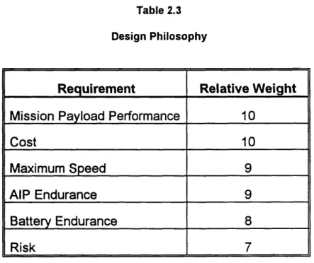
The final piece of logic to be communicated in this statement of owner's requirements is the priority to be assigned to the attributes which are mutually exclusive of each other. This design philosophy is usually stated in some form of hierarchy, assigning relative weights to the attribute the owner considers most important. This concept is illustrated in Table 2.3.
With the required missions determined, the required capabilities in several areas stated and the relative priority for meeting the desired capabilities established, the design team can proceed with concept exploration.
As an example of the type of trade-offs to be made, consider submerged endurance on the battery. For a given battery type, increasing endurance for a given speed on battery power alone means increasing the battery size, weight and cost. If the battery is larger, the ship size may have to be increased to
Table 2.2
Statement of Requirements
support the increased battery weight. Increasing both the battery and ship size will most likely increase the cost of the ship. By Table 2.3, cost is a higher priority (10) than battery endurance (8). Therefore after the impact of increasing battery endurance on the overall ship cost is studied, one might expect that battery endurance would be sacrificed to keep costs down.
Requirement Goal Threshold
Diving Depth 1000 feet 700 feet
Range: Snorkeling
@
10 kt SOA 15,000 nm 10,000 nmSubmerged @ 8 knots (AIP) 30 days 20 days
Submerged
@
4 knots (battery) 120 hours 90 hoursSubmerged ( maximum speed 5 hours 2 hours
Endurance 90 days 60 days
Speed: Submerged, maximum 24 knots 20 knots
Snorkeling, sustained 12 knots 10 knots
Surfaced, maximum 15 knots 12 knots
Indiscretion Rate: Transit @ 10 knot SOA 0.3 0.4
On station 8 knots 0.05 0.1
Weapons: Number of Torpedo Tubes 6 4
Total Weapons Load 24 16
Weapons Type > Threshold Torpedoes/Cruise
_eapons Tresold Type> Missiles/Mines
Manning 40 men 50 men
Main Ballast Tank Volume (% of everbuoyant 15 12
volume)
Lead Ballast (% of normal surfaced condition) 10 5
Table 2.3
Design Philosophy
2.3 SUBMARINE HULL SYNTHESIS
With the ships requirements stated, the process of determining the size of the submarine can begin. While the details of the submarine model will be discussed in Chapter 6, the basic concept of submarine hull generation will be presented here to give a better understanding of the impact of the AIP propulsion options, power sources and reactants on submarine design when
explained in Chapters 3, 4 and 5.
For this thesis, the shape of the hull will be assumed to be a body of
revolution, modeled after the hull of the submarine ALBACORE. This basic shape has the best underwater hydrodynamic performance, which will be important to best utilize the power available from the AIP power plant.
Even though a modern submarine is designed to spend most of its
operating time submerged, Archimedes' principle for flotation of hull weight is applicable in both regimes. As seen in Figure 2.2, the first logical step from ship
Requirement Relative Weight
Mission Payload Performance 10
Cost 10
Maximum Speed 9
AIP Endurance 9
Battery Endurance 8
requirements is weight estimation. Extensive data bases have been developed which catalogue existing equipment and structural weights. From these data bases, parametric curves have been developed which can be used to estimate each of seven major weight categories, which form the fixed weight of the ship. To this fixed weight is added lead ballast, part of which is used to balance longitudinal moments later in the design process and part to allow for weight growth in equipment over the life of the ship. Also to be accounted for are the variable weights on the ship, which include fluids; such as fuel and fresh water, stores; such as food and spare parts, and weapons. This summation of weights represent the total weight which must be supported at all times when the ship is on the surface and is designated as the normal surfaced condition (NSC). The left hand column of Figure 2.3 summarizes this weight summation process.
Similar to the weight estimation database, data exists for the pressure hull volume necessary to enclose the equipment, crew and weapons carried by the ship. From these volumes, established parametric relationships are employed to estimate the pressure hull volume. Add to this volume all the items such as ballast tank structure, hull plating and equipment which exist outside the pressure hull and you have the portion of the ship which will never flood with water and is termed the everbuoyant volume (VEB). The everbuoyant volume is equivalent in concept to the NSC and is the point where estimated weights and volumes are reconciled. For the ship to achieve neutral buoyancy, the estimated weight of the ship must equal the weight of seawater displaced by the everbuoyant volume. If NSC is greater than VEB, the ship is said to be weight limited, with the ship not displacing enough water to float the submarine on the surface. If VEB is greater than NSC, the ship is said to be volume limited with the ship requiring more weight to achieve neutral buoyancy. To bring these two
Weight Estimation Volume Estimation
Group I (Hull) a. Mobility
Group 2 (Propulsion Machinery) b. Weapon
Group 3 (Electrical) c. Command and Controlc. Command and Group 4 (Electronics) d. Auiliaries
Group 5 (Auxiliary Equipment) e. Habitability Group 6 (Outfit & Furnishings) f. Storerooms Group 7 (Weapons)
EGroup 1 ..7 function (a..f)
... ... ....I. .. . ... ... .
Condition A-i Pressure Hull Volume (Vph)
A-I + Lead Ballast factor ' Vph ... ... ... .. ... ... ...
Condition A ' Outboard Volume (Vob) A + Variable Load Vph + Vob
Balance
Normal Surface Condition Everbuoyant Volume (Veb) ... ... ii... .. ...... iii/... ...
Main Ballast Tank Volume (Vmbt) = factor *Veb ... . ... ... ... .. ...11 ..111. .111111 .111111 :11... 1 ii... ... i ...
Submerged Volume (Vsub) = Veb + Vmbt
. -. . ... .
Freeflood Volume (Vff) = factor * Veb Ene....
.Vo ... .u ?nv) E_... ...
Envelope Volume (Venv)
Balancing Weights and Volumes Figure 2.3
concepts together, either volume is added to the weight limited ship, or lead
ballast added to the volume limited ship, rather than immediately refining any estimates made of the weights and volumes. When the best value for VEB has been established, the margin required for main ballast tank volume is applied, along with an estimate of the volume of the ship which is free flooding on submerging to obtain the volume of the hull envelope. This envelope represents the hull form and weight that must be propelled by the ship when submerged and forms the starting point for the powering calculations.
The next several steps refine the estimates made above in determining
added appendages is used to estimate the effective horsepower (EHP) of the ship. EHP is the power necessary to push the hull through the water at various speeds. The choice of propulsor and efficiencies associated with water flow past the stern and propeller combine to estimate the propulsive coefficient (PC), a measure of how effective the propeller is in converting the available shaft horsepower (SHP) to EHP. With SHP determined, a check of the initial propulsion machinery estimate can be made. Likewise, a preliminary set of arrangement drawings is made to ensure compartment layouts are sensible, to locate weights and calculate moments to check the longitudinal stability of the ship. Additionally with the principal hull dimensions known, the pressure hull and its required scantlings can be estimated to refine initial estimates for structural weight.
Finally, the dynamic performance of the ship is evaluated through the use of computer simulation and model testing to verify that the hull form and the first estimate of sail and control surface size and location result in acceptable underwater performance. Upon completion of this final check, the first trip around the design spiral is complete. Now the design team must come together to compare results, perform trade offs guided by the design philosophy, and make any necessary changes to the initial weight and volume estimates. With these revised values, the procedure just outlined is revisited, with the end result being a more balanced ship. This circular procedure is repeated until the best design is produced.
CHAPTER THREE
3.0 SUBMARINE SYSTEMS
The systems required to support a submarine's operating profile contain many aspects of those found in standard shipboard applications. These systems are however complicated by the special considerations unique to submarine operations, such as buoyancy systems for diving and surfacing and atmosphere control. Conventional system designs are comprised of a central plant (electric, hydraulic, pneumatic, etc.) and some form of distribution / energy storage network. Systems of this type are important for several reasons, a primary one being the conservation of space and power, since a hydraulic operator for a valve is many times smaller than an equivalent motor operator. A general description of the more important systems will be presented to provide a background for the AIP plant size decisions.
The integration of a shipwide electrical system with propulsion and ship service requirements is most critical to the make up of a conventional submarine. Relying on different power sources at different times in an operating profile, these sources must be capable of providing continuous power in parallel, whether in transition between sources or together to increase the available output power. The types of power available, and the load requirements go a long way in determining the architecture of the system.
Power sources, discussed in detail in Chapter 4, include electro-chemical which provide a direct current (DC) output and mechanical, which can be fitted with either an alternating current (AC) or DC generator to provide electrical
power. Ship service electrical loads, Section 3.2, depend on the type of
power. Propulsion loads have been predominantly DC power based, but emerging technology has pushed AC and low voltage high current DC power applications to the forefront, and are discussed first in Section 3.1.
3.1 PROPULSION INTEGRATION
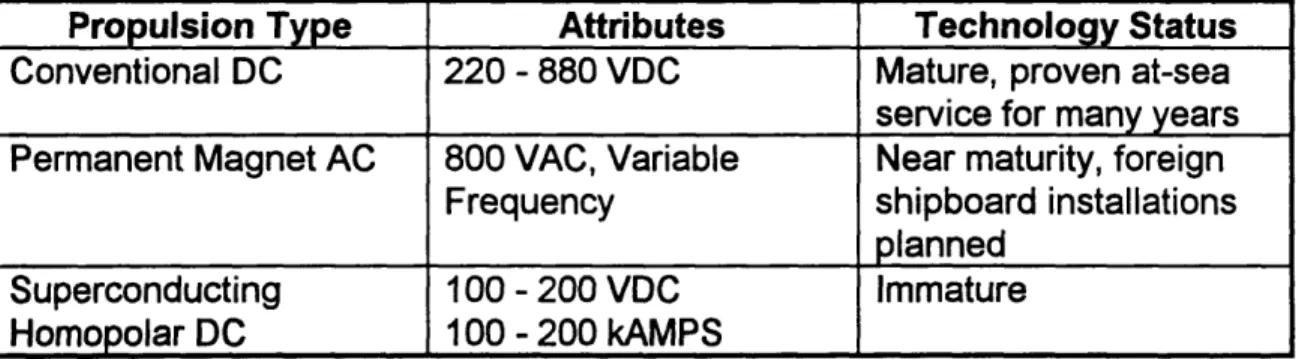
Table 3.1 presents a summary of possible propulsion options to be considered in this study.
TABLE 3.1
Propulsion Options
Propulsion Type Attributes Technology Status
Conventional DC 220 - 880 VDC Mature, proven at-sea
service for many years Permanent Magnet AC 800 VAC, Variable Near maturity, foreign
Frequency shipboard installations
planned
Superconducting 100 -200 VDC Immature
Homopolar DC 100 -200 kAMPS
3.1.1 CONVENTIONAL DC
Advantages Disadvantages
-Reliable Technology -Large WeightNolume
-Compatibility with Battery Systems
The most common arrangement in service is the conventional DC motor from a high voltage (220 - 880 VDC) bus, which until recently was the only viable technology available. Double armature motors with creative battery switching
Basic Circuit Mode I L HA '- {RlI M )
I
HiK) M1( i I I L I IMode 2 Mode 3 Mode 4 Mode 5
Battery Stepping Operating Modes for a Double Armature DC Motor [27]
Figure 3.1
schemes such as Figure 3.1 gives the operator flexibility in terms of speed control and system configuration. Based on its vast historical operating experience, this concept is well proven in terms of reliability. While improvements have been made, these machines are heavy and volumous when compared to AC machines of similar power output. Their widespread use however is a result of their excellent low speed torque characteristics and their ready compatibility to the varying DC voltage characteristics of the traditional Lead-Acid battery based electrical distribution system.
ii
_ - -7:f:
iI
l: .. rL
c
3.1.2 PERMANENT MAGNET AC
Permanent Magnet AC (PM) motor technology is being developed and may gain acceptance as the possible successor to the conventional DC system. The PM motor, illustrated in Figure 3.2 uses permanent magnets to
Permanent Magnet Axial Gap Propulsion Motor [16]
Figure 3.2
Advantages Disadvantages
-Reduced Weight / Volume -Requires DC/AC Inverters -Heat Losses in Rotor Eliminated -Heat limits in PM materials
-Current collectors not mature
7
replace the magnetic field source on the rotor eliminating significant amounts of electrical wiring. In this design the rotor, and stator are disc shaped vice a conventional can shaped stator encircling the rotor core. With the disc geometry, a larger number of poles can be included, with smaller end turn volumes and reduced stator back iron size and weight, giving the motor a higher degree of speed control. Estimates of the weight and volume savings for PM motors over comparable DC motors are on the order of 50 and 40 percent, respectively [28]. This technology can also be applied to power generation applications with similar savings in weight and volume. Figure 3.3 illustrates one concept design currently under evaluation at the Naval Surface Warfare Center, Annapolis [18]. The cup shaped rotor with the stator located inside is designed to counter centrifugal forces generated by spinning the rotor magnets at speeds
up to 12,000 revolutions per minute (RPM).
~ .~. .:'~.' I ...
~~~~~~~~~~~~~~~~~~~~~~~~~~~~~~~~~~~~~. . . . .. .
2·22. ~ Mane
i~''3
ATi~
j~~.~iiiiii
~I·I Mzt R O .. T-. O R
Permanent Magnet High Speed Generator
Figure 3.3
PM motors, however, require a slowly varying AC frequency that will allow the motor to operate at very low speeds. This frequency can be achieved
... .... ....:·: :::::· iiiii~~~iiiiiiiiii~~~~~i~. ~ ~ ~ ~ % ... ... :i~~~~~~~j::j... C:~:ii:·::~:::j:::::::::.~I... ... . .. ...::·: ·· "WAT~~~~~~~~~~~':"i~:r''' ... ... ... ;:;2 . ...iiii a ...::: :~~:::::::~~::::i:~~~::.. .. ... X ... ...'j~ ... .. ...~::ll~li ... :: :: . · ·· · :: · ·:·. :·· ....
through the use of power electronics to chop a DC input signal to provide an
output AC voltage of the appropriate frequency, Figure 3.4. Alternately, this AC voltage can be created by using a DC motor - AC generator set, varying the speed by control of the DC motor field.
0
0
Input DC Voltage Output AC Voltage
Example of Chopped AC Output From Input DC
Figure 3.4
3.1.3 SUPERCONDUCTING HOMOPOLAR DC
While still an immature technology in its final form, the Superconducting Homopolar (SC) motor is a next generation of propulsion technology, taking advantage of "zero" resistance properties of electrical conductors when they have been cooled to near zero degree Kelvin conditions. The SC motor
Advantages Disadvantages
-Reduced Weight / Volume -Requires Cryogenic Cooling -Reduced Noise / Direct Mounting to -High electrical currents
Warfare Center, Annapolis [6]. Employing basic Lorentz force principles, the motor contains large super conducting coils in a stationary cryostat cooled to 40K, generating a torroidal magnetic force which appears radially outward in the active region of the motor. Because the resistance of the coils is very close to zero, a large current can be applied creating a very strong magnetic force for the stator current to operate against. This allows the motor to generate very large values for torque relative to the size of the machine. To the detriment of the concept, the cryostat, which contains liquid helium requires a separate cryogenic plant to maintain the temperature which draws approximately 100 kW of power, a significant penalty in an AIP application. Also, the current collectors, which are Sodium-Potassium liquid metal, are sensitive to water absorption causing corrosion problems and disperse under high rotational speeds.
Armature
Stator Bars
V
Current Collectors
Superconducting Homopolar DC Motor Figure 3.5
3.1.4 PROPULSORS
The standard submarine propulsor is of fixed pitch design, specially designed to minimize the effects of cavitation while submerged. Other styles of propulsors, such as contra-rotating (CR) or ducted propellers have been proposed and installed on submarines, but problems of one type or another have kept them from gaining acceptance. The CR propeller offers a 10 percent increase in the propulsive coefficient for a submarine application [12]. Historically, the problem with a contra rotating system has been the transmission of power through some form of reduction gear to the propulsion shaft. The emergence of PM and SC technology, with its compact design, offers a good solution to this dilemma [19].
3.2 SHIP SERVICE POWER REQUIREMENTS
While the propulsion load will vary constantly, the ship service or hotel load of the submarine will remain fairly constant for a given operating profile. Included in this hotel load are the minimum power requirements for ship control and operation and atmosphere control. These loads can be expected to vary for each operating profile of the ship, such as a battle station condition when all
crew members are on station and most systems are operating, to an ultra quiet condition when most crew members are retired and only a minimum number of systems are operating.
Most equipment is operated by some form of electricity from a ship service bus. Conventional submarines generally employ ship service busses that are DC power based because of their link to the storage battery, thus any load that cannot operate off a DC voltage source that varies with the state of charge on the battery must be converted. Motor generator sets or static power
Typical Loads
120 VAC, 60 cycle
450 VAC, 60 cycle
Bilge Pumps, Lighting, Atmosphere
Monitoring Equipment, Appliances Ventilation Fans, Hydraulic Pumps, Air Compressors, Galley Equipment
120 VAC, 400 cycle Precision Electronic Equipment (Gyro
compass, weapons control, etc.)
High Voltage DC Trim Pumps, Lube Oil Pumps,
(Direct from Battery Bus) Lighting
Low Voltage DC Ship Control, Sonar Equipment Power
The loads above are typical of those developed for nuclear powered submarine applications which use an AC ship service bus, and for some uses be adapted to a different more convenient source. Figure 3.6 illustrates a typical ship service power architecture. 400 Hz AC Direct Loads 60 Hz AC Dies Genei DC
4' AIP Power Source
Typical Ship Service Distribution System
Figure 3.6
3.3 AUXILIARY SYSTEMS
The electrical distribution network is but one small part of the vital submarine support network. A fully integrated system of pneumatic and hydraulic controls and operators supplements the ship operations, providing compact, high powered operating mechanisms for large equipment such as diving planes, masts and antennas and seawater valves. Most systems are comprised of a central power plant where the energy of that system is created, then distributed to various operating points or to storage locations. For example, a typical hydraulic system features a storage tank, pump and high pressure accumulator all in one package which then feeds a hydraulic distribution system, Figure 3.7. A typical pneumatic system features air compressors connected to a high pressure air header, which feeds high pressure air storage bottles and a distributed network of lower pressure air systems, Figure 3.8. Here the air storage bottles are spread throughout the ship, typically in the vicinity of the main ballast tanks to provide an immediate emergency source of surfacing air. These types of systems are important supplements to the electrical network because of their simplicity in operation, their reliability in the face of a propulsion plant casualty, and the energy density available in the high pressure fluids they contain.
3.4 ATMOSPHERE CONTROL
A vital distributed auxiliary system, but one which seems far less defined is the ventilation / atmosphere control system. This system comprises the necessary fans and ductwork to bring air into the ship, recirculate it when
submerged and purify it so that the air continues to be breathable. All
Towed Array Winch
Seawater Valves Diving Planes
Hydraulic System with Typical Loads
Figure 3.7 700 PSI 20 PSI 150 PSI 250 PSI 400 PSI Main Air Header
Air Bottles
(Located in Ballast Tanks)
000
@ 450)0 PSI Air Compressorsr
, v 0(00
High Pressure Air System
Figure 3.8 Reduce To Emergency Ballast Tank Blow System ,A
Trim Valves Masts/ Antennas
such as carbon dioxide (CO2), carbon monoxide, hydrogen and odors, and replacing the oxygen consumed by the crew. Conventional diesel submarines rely on the fact that they snorkel periodically and use that opportunity to exchange air with the atmosphere and are therefore concerned with how to bridge the gap between snorkel evolutions. These ships typically employ Chlorate Candle canisters which are burned to produce oxygen and a chemical reactant such as Lithium Hydroxide to absorb CO2 An AIP submarine could employ similar methods for atmosphere control, but storage requirements for these expendable canisters could limit the submarine's endurance. Since it will be shown that some AIP options include liquid oxygen storage, this tankage can be increased by the necessary amount to include breathing oxygen for the crew for the entire patrol, estimated to be 0.030 ft3 of liquid oxygen per person, per day of patrol [7]. This parasitic use has an additional advantage in that it can be used as a load for the boil off that occurs during normal storage of oxygen as a
liquid. CO2 removal can be accomplished by the use of scrubbers which use a
monoethanolamine (MEA) spray to absorb CO2from the air, releasing it to an overboard discharge system. Such a system is regenerable, however its penalty is an additional electrical hotel load on the order of 6 kW. Also of concern is the potential build up of hydrocarbons and hydrogen gas which can be cleaned up through the use of burners, again at an electrical cost of about 9 kW [71].
By locating this atmosphere control equipment in one location, the air can be recirculated throughout the submarine and passed through this "room" to be revitalized. Oxygen can be bled into the submarine at various locations so help distribute it evenly throughout the ship. Figure 3.9 represents a typical ventilation arrangement.
Ventilation Arrangement
CHAPTER FOUR
4.0 POWER SOURCES
Many AlP power plants have been proposed, with development conducted by those countries that have a genuine interest in promoting air independence for their own submarines or for the commercial submarine market. This chapter investigates current and proposed power source options.
An AIP power plant is composed of several parts combined into one
functional system. These parts are:
- Energy conversion device - Fuel source
- Oxidant source
- Waste product management.
Reactants, which include fuels and oxidants, and waste product management, which can involve the storage of pure water or discharging high volumes of carbon dioxide overboard will be examined in Chapter 5.
The energy conversion device can be categorized as either electro-chemical or mechanical, depending on how the energy conversion is performed. Mechanical AIP concepts include compact heat engines modified to run in the absence of a normal atmosphere such as the closed cycle diesel, to entire cycles, such as a Rankine cycle whose heat source is a simple combustor burning hydrogen and oxygen. A discussion of these plants can be found in Section 4.2. Electro-chemical concepts include a range of fuel cell and high performance primary and secondary battery options and will be discussed first.
4.1 ELECTRO-CHEMICAL CONCEPTS
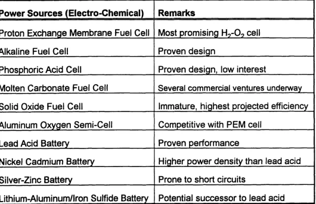
Table 4.1 summarizes the electro-chemical power concepts to be investigated.
Table 4.1
Electro-Chemical AIP Concepts
4.1.1 FUEL CELLS
Fuel cells represent a major area of interest among AIP power source options, presenting a potential for very high efficiencies since the energy conversion process is not limited by Carnot principles. As seen in Figure 4.1, their projected efficiency is roughly double that seen with heat engine cycles, which can translate into large savings in fuel and oxidant for a given submarine hull [29]. A fuel cell can be thought of as a black box where chemical reactants
Power Sources (Electro-Chemical) Remarks
Proton Exchange Membrane Fuel Cell Most promising H.-O. cell
Alkaline Fuel Cell Proven design
Phosphoric Acid Cell Proven design, low interest
Molten Carbonate Fuel Cell Several commercial ventures underway
Solid Oxide Fuel Cell Immature, highest projected efficiency Aluminum Oxygen Semi-Cell Competitive with PEM cell
Lead Acid Battery Proven performance
Nickel Cadmium Battery Higher power density than lead acid
Silver-Zinc Battery Prone to short circuits
i flicicncv i) 'I) V) In In IFuel (cal Aluminum Peroxide Stirlina inRmeC CC 1)ie.cl I.P Nuclear Jo40 6( 90 1 00 ltoad Factor o
Efficiency vs. Load for AIP Options
Figure 4.1
are introduced and combined, utilizing an electrical load to complete the transfer of electrons between anode and cathode, thereby creating a DC electrical power source. There are many proven fuel cell designs over a wide range of power
levels, however the auxiliary equipment necessary to support these cells, and
the materials themselves may not be compatible with submarine applications. As a result, only those technologies which appear to be favorable will be considered.
4.1.1.1 PROTON EXCHANGE MEMBRANE FUEL CELL
The Proton Exchange Membrane (PEM) cell is presently the most popular fuel cell in terms of interest and development for submarine applications. This thought is underscored by German industry, which after successfully demonstrating a small alkaline fuel cell plant in a Type 205 submarine in 1987, has abandoned that variety of cell in favor of the PEM cell [29]. The PEM cell is also being studied as a part of AIP development programs in the United
Kingdom, Canada and Australia. In addition, the US Navy has developed PEM
technology for replacement of alkaline cell technology in the oxygen generating equipment found onboard its nuclear submarines [55].
The PEM cell is a standard hydrogen-oxygen cell, depicted in Figure 4.2, except that the electrolyte is actually a solid polymer material rather than a liquid ionic material such as potassium hydroxide or phosphoric acid. Hydrogen is introduced at the anode where a catalyst forces the release of electrons. Hydrogen ions then pass through the polymer material to the cathode where they combine with oxygen and free electrons to form water. The electrical circuit is formed by insulating the anode and cathode electrically, forcing the electrons released at the anode to transit via an electrical circuit to the cathode where they are required to complete the reaction [13].
Advantages Disadvantages
-Proven technology -Hydrogen storage
-"Solid" cell technology -Requires pure reactants
-Quiet / reduced heat rejection -Reformer for non-hydrogen fuels
-Pure water product (immature)
-Low operating temperatures (1 80F) -Cell poisoning due to impurities reduces output
- Hydrogen
Water
Overall Cell Reaction:
H2+
2O2
--
H20
Proton Exchange Membrane Fuel Cell [39]
Figure 4.2
The size of the fuel cell is flexible and can be tailored to the application. While most specific information is proprietary, a single fuel cell can be expected to generate an output voltage of slightly less than 1.0 VDC with a current density on the order of 1 amp per square centimeter. Thus for a certain power requirement, individual cells can be connected in series to achieve the required output voltage, with enough active area to achieve the required amperage (power) rating. Figure 4.3 shows a typical cell voltage versus load profile.
The PEM cell requires relatively few auxiliary systems to support its operation. The electrolyte is solid, requiring no makeup or monitoring system as
1 0.9 _ 0.8
p
0.7
0.61 0.5
o' 0.4
= 0.3 L 0.2 0.1 0 0 0.5 1 1.5 2Current Density (Amps/cm2)
PEM Cell Voltage versus Cell Load [74]
Figure 4.3
in liquid electrolyte designs, greatly improving its simplicity. The cell is classified as low temperature in comparison to other systems. With an operating temperature around 2000F, the time required for the cell to reach operating temperature is relatively short, making it ideal for rapid start-up, an important operating characteristic. The lower operating temperature is also more compatible with an enclosed submarine environment [44]. The only product discharge from the cell is pure water, which is potable and easily handled, either by storage for crew consumption or transfer to a variable ballast system for discharge overboard. A significant issue for the PEM cell is the fuel source. The solid polymer electrolyte membrane is susceptible to contamination by impurities in the fuel gas, specifically carbon monoxide, a by-product of the reformation process. While carbon monoxide contamination does not permanently damage the cell, concentrations as high as 10 PPM can
dramatically affect cell performance, requiring regeneration of the cell with a clean gas source [3]. Development of a "clean" reformer is a significant developmental issue and is discussed further in Section 5.1.1.3.
Specific details on the PEM cell can be found in Appendix A.
4.1.1.2 ALKALINE FUEL CELL
This fuel cell is very similar in concept to the PEM cell with exception of
the electrolyte and its added complexities, and has been demonstrated to
operate successfully at sea in a German Type 205 submarine. This system used potassium hydroxide to conduct the hydrogen ions to the cathode for
recombination [55]. Figure 4.2 presented earlier for the PEM cell applies to the
alkaline cell as well.
4.1.1.3 PHOSPHORIC ACID FUEL CELLS
Advantages Disadvantages
-Demonstrated performance "at-sea" -Hydrogen storage
-Quiet / reduced heat rejection -Liquid electrolyte / more complex
-Pure water product than PEM
-Low operating temperatures (1 800F) -Requires pure reactants
-Reformer for non-hydrogen fuels
(immature)
Advantages Disadvantages
-Demonstrated commercial -High operating temperatures (4000F)
performance -Liquid electrolyte / more complex
-Quiet / reduced heat rejection than PEM
-Pure water product -Larger / heavier than PEM, same -Can reform hydrogen fuels internally efficiency
Another variant of the basic hydrogen oxygen fuel cell is the Phosphoric Acid Fuel Cell (PAFC), which is conceptually similar to the alkaline cell. using phosphoric acid as an electrolyte. While this cell is fueled by pure hydrogen, variants operated at higher temperatures (4000F) may be able to reform hydrogen based fuels internally as this cell is not susceptible to carbon monoxide poisoning [21]. Commercial development of the PAFC as a "portable" remote power source fueled with natural gas is mature. At issue for submarine applications are the significantly larger volumes and weights for similar efficiency
when compared to PEM technology and lower efficiency when compared to
other similar sized high temperature cells to be discussed [65].
4.1.1.4 MOLTEN CARBONATE FUEL CELL
The Molten Carbonate Fuel Cell (MCFC) is similar to other fuel cells in its
basic principle of operation, however its method of achieving energy conversion
Advantages Disadvantages
-Internal conversion of fuel -High operating temperatures -Variety of fuels possible (12000F)
-Higher system efficiencies -Safety to personnel
-High system temperatures utilized in -Long start up time
fuel reformation -Corrosion issues
-Active commercial interest -Large/heavy compared to other fuel -Can support bottoming cycles cell plants
is quite different. Illustrated in Figure 4.4, the MCFC utilizes a molten carbonate salt as the electrolyte, and thus must be heated to around 1200F to function. If properly insulated, this high heat can be used to internally reform any number of hydrogen based fuels, such as marine diesel or methanol, making this option especially attractive. Similar to the PEM cell, pure water is produced as a result of the reaction, however other products, such as carbon dioxide are produced as well. The relative volume of carbon dioxide gas produced depends on the type of fuel used in the cell. Because of the high temperature of the cell, the waste heat from the cell can be used to operate some form of bottoming cycle, improving overall system efficiency [65].
Appendix A contains more specific data on MCFC
Hydrogen Fuel IN -C02 OUT Water OUT 4 Oxygen IN CO2 IN
Reaction
on Cathode
Surface:
½02
+ C02 +2e-
CO3=Reaction on Anode Surface: H2 + C03= - C02 + H20
+
2e-Molten Carbonate Fuel Cell
4.1.1.5 SOLID OXIDE FUEL CELL
The Solid Oxide Fuel Cell (SOFC) is a new, advanced technology which is still very immature. Similar to the MCFC, it operates at high temperature (18000F) and can therefore internally reform various types of fuel. Its electrolyte however is a solid, nonporous metal oxide, eliminating the need for a liquid electrolyte management system. The higher operating temperature of the SOFC promises that it should enjoy a higher efficiency than the MCFC, and projections are that SOFC technology should be very weight and volume efficient [65]. One design by Westinghouse for possible shipboard applications is shown in Figure 4.5. Here an oxidant is passed inside a cylindrical cell with the fuel gas passed on the outside. Similar to other fuel cell applications, the ceramic metal oxide passes oxygen ions through to the cathode where they combine with hydrogen and carbon monoxide to form carbon dioxide and water.
4.1.1.6 DIRECT METHANOL OXIDATION FUEL CELL
This cell represents research in PEM technology aimed at eliminating the reformer requirement when using fuels other than pure hydrogen. It is very
immature and is not formally evaluated in this study.
Advantages Disadvantages
-Internal conversion of fuel -Immature technology
-Variety of fuels possible -High operating temperatures
-Highest system efficiency (projected) (1 8000F)
-High system temperatures utilized in -Safety to personnel
fuel reformation -Long start up time
The cell operates at low temperature and contains the solid polymer electrolyte. The difference is a special catalyst at the anode which transforms methanol fuel into hydrogen and carbon dioxide, a gas with no effect on cell efficiency. Present cell performance has an output voltage of 0.6 VDC (slightly less than PEM) at a current density of 0.1 Amps/cm2 (1/10th of the PEM cell)
[37]. Electro Air Electrod Air / Flow
Reaction on Anode Surface:
Reactions on Cathode Surface:
02 +
4e-
-->
20=
2H2 + 20 -> 2H20 +
2CO + 20 - 2C02 +
4e-Westinghouse Solid Oxide Fuel Cell [5] Figure 4.5