Publisher’s version / Version de l'éditeur:
Vous avez des questions? Nous pouvons vous aider. Pour communiquer directement avec un auteur, consultez la première page de la revue dans laquelle son article a été publié afin de trouver ses coordonnées. Si vous n’arrivez pas à les repérer, communiquez avec nous à [email protected].
Questions? Contact the NRC Publications Archive team at
[email protected]. If you wish to email the authors directly, please see the first page of the publication for their contact information.
https://publications-cnrc.canada.ca/fra/droits
L’accès à ce site Web et l’utilisation de son contenu sont assujettis aux conditions présentées dans le site
LISEZ CES CONDITIONS ATTENTIVEMENT AVANT D’UTILISER CE SITE WEB.
Paper (National Research Council of Canada. Division of Building Research); no.
DBR-P-846, 1978
READ THESE TERMS AND CONDITIONS CAREFULLY BEFORE USING THIS WEBSITE. https://nrc-publications.canada.ca/eng/copyright
NRC Publications Archive Record / Notice des Archives des publications du CNRC : https://nrc-publications.canada.ca/eng/view/object/?id=ef73c00d-a22c-4a8d-8be2-4bf9dab851a6 https://publications-cnrc.canada.ca/fra/voir/objet/?id=ef73c00d-a22c-4a8d-8be2-4bf9dab851a6
NRC Publications Archive
Archives des publications du CNRC
This publication could be one of several versions: author’s original, accepted manuscript or the publisher’s version. / La version de cette publication peut être l’une des suivantes : la version prépublication de l’auteur, la version acceptée du manuscrit ou la version de l’éditeur.
For the publisher’s version, please access the DOI link below./ Pour consulter la version de l’éditeur, utilisez le lien DOI ci-dessous.
https://doi.org/10.4224/40001683
Access and use of this website and the material on it are subject to the Terms and Conditions set forth at
Fire resistance of structural steel
Ser TH1
B21d no.
846
c.
,Aa
7 . u ~
National Research Council of Canada
Conseil national de recherches du Canada
FIRE RESISTANCE OF STRUCTURAL STEEL
by T. T.Lie
Reprinted from
Engineering Journal
American Institute of Steel Construction
I
Fourth Quarter, Vol. 15, No. 4, 1978
p. 116-125
DBR Paper No. 846
Division of Building Research
S'OMMAIRE
L'article dtcrit une mtthode de calcul du rendement de I'acier de charpente durant un incendie. Une formule simple permet de comparer la rtsistance au feu de l'acier de charpente lorsqu'il est soumis 2 un essai de rksistance au feu et celle obtenue dans le cas d'un vtritable incendie. Une analyse a indiqut que la charge thermique 2 laquelle une pi& de charpente peut resister au cours d'un incendie est proportionnelle 2 la rCsistance au feu normale attribute 2 l'tltment de charpente. L'article traite aussi de l'in- fluence des facteurs importants qui dtterminent la charge ther- mique critique, soit le facteur d'ouverture, l'tpaisseur du re- vCtement protecteur et la masse de l'acier.
Fire Resistance of Structural Steel
T. T. LIE
Because a factor of safety is incorporated in design calcu- lations, load-bearing members in a building generally possess reserve strength. This gives the member resistance to extreme loads such as floor load concentrations. wind. snow, and earthquake, and at the same time resistance to fire.
During a fire, the member may be exposed to heating at extremely high temperatures, and as a consequence its strength may decrease substantially in a short time. T o prevent such loss of strength it is essential to protect the member against excessive temperature rise.
One of the problems in selecting appropriate protection is the evaluation of its effect on the fire performance of the member. Usually, fire performance is determined by subjecting a member to a standard fire.' In practice, how- ever, the severity of fire conditions can vary over a wide range. It is desirable, therefore, to find some means by which the performance of a member in a standard fire can be used to assess its ~erformance under fire conditions more representative of those that might actually be expected.
How standard fire resistance can be related to fire re- sistance in practice has been introduced, in principle, in a previous study.13 In the present paper the method is applied to structural steel protected by materials having various thermal properties. The influence of fire severity on the fire performance of steel members, as well as the influence of other important factors that determine their fire resistance, are examined.
FACTORS AFFECTING FIRE SEVERITY
It is known that the temperatures reached in a room fire and their duration are determined bv such factors as quantity, nature, dimensions, and configuration of the combustible materials, the dimensions of the room. and the openings through which air, necessary for combustion, can enter the room.4,5~7,'4,'5,19,20
At present it is possible to estimate the fire temperature course if the values of the various factors that determine it are known. However, several factors, such as amount and dimensions of combustible materials, are unpredictable in
T. T. Lie is Research Officer, Fire Research Section, Division of Building Research, National Research Council of Canada, Ottawa, Canada.
practice, because they change with time and often vary from room to room in a building. It is not possible, therefore, to know at the time a building is constructed the temperature course to which a member may be exposed should fire occur during the service life of the building.
It is possible, however, to make conservative assumptions with regard to the values of various uncertain factors and to derive fire temperature-time curves that probably will not be exceeded in the event of a fire. This is the case, for example, if the fire is controlled by the amount of air en- tering the room, which, in turn, is determined by the di- mensions of openings into the room. For such fires, which are known as ventilation-controlled fires, the number of factors that determine the temperature course can be re- duced to three:9
1. The opening factor, F , defined as:
1
F=- (see Ref. 7)
AT
where
A, = area of openings in the room
H = height of openings in the room
AT = area of internal bounding.surfaces (walls, floor, and ceiling)
2. The fire load,
Q,
which may be defined as the amount of combustible material per unit area of the internal bounding surfaces3. A factor, C, that takes into account the influence of the thermal properties of the bounding material on the fire temperature course
An analytical expression exists for the dependence of the temperature of ventilation-controlled fires on these three fact01-s.~ Figure 1 shows (for an opening factor of F = 0.009 ft'/2) how fire load affects the fire temperature course. In general, the duration of the fire increases with the fire load, and the intensity of the fire increases with the opening factor. The wall material also affects the intensity of the fire. The better the insulating quality of the walls, the higher the temperature in the room. T h e influence of the wall material, however, is relatively small in comparison with that of the fire load and ventilation. In this study, therefore, a constant value of C = 0 will be assumed, rep-
,.
0 1 3 4 5 6 7TIME, h
Fig. I . Characteristic fire temperature curvesfor various fire loads (QI
resenting a heavy wall material such as normal weight concrete and most clay and sand lime bricks. The influence of the two most important factors, i.e., fire load and venti- lation, on the fire temperature course and the fire perfor- mance of steel members will be considered in more de- tail,
CRITICAL STEEL TEMPERATURE AND CRITICAL FIRE LOAD
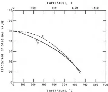
It is known that the strength and rigidity of steel decreases when it is heated to elevated temperatures. In Fig. 2, curves derived from existing data12 illustrate how these properties vary with temperature. If the duration of the fire is suffi- ciently long, a point will be reached at which the member can no longer perform its load-carrying function. T h e av- erage temperature of the cross section of a steel member at which this occurs is defined as the critical temperature.
Whether, during a fire, the steel temperature rises to the critical temperature depends to a large extent on the fire load. The higher the fire load the longer the duration of the fire and the higher the maximum steel temperature. If there is sufficient fire load, the critical temperature will be reached. A fire load that is just sufficient to raise the steel temperature to the critical temperature is defined as the critical fire load.
T h e critical temperature of steel members depends on several factors. For steel beams, the most important are loading, steel properties, and end conditions. In general, the critical temperature of beams fixed at the ends is higher than that of simply supported beams. For columns, the same factors also play an important role in determining the critical temperature, with the addition of the slenderness of the column.
A survey indicates that, owing to the influence of various factors, the critical steel temperature can vary over a wide range normally lying between 750 and 1200°F. For the purpose of this study, which is intended to examine the influence of fire load and ventilation on the fire perfor-
'!I
1:O 2;O 3!lO 4!lO 5;O 6;O 7:O 8:O 9I!O T E M P E R A T U R E , " CT E M P E R A T U R E . " F
3 2 4 0 0 750 1100 1450
Fig. 2. Yield strength (Fy) and modulus of elasticity (E) of carbon steels as a function of temperature
140 u 1 2 0 - 2 2 a >
mance of protected steel, it will be assumed that the critical temperature of the steel is given. In this case, it will be as- sumed that the critical temperature of the steel is 1000°F, which is equal to the critical temperature specified by ASTM El 19l for steel beams and columns.
If the critical temperature is known, determination of the length of time a specific steel member can resist expo- sure to fire can be simplified to calculation of the temper- ature rise of the steel and determination of the time to reach the critical steel temperature.
I
I 1I
I 1 1 I 1-
METHOD OF CALCULATING STEEL TEMPERATURE
-
-
tx 0 t L O 60-
-
Y w a 5 4 0 --
u U tx W " 20-
-
Recent developments, particularly with respect to nu- merical techniques, have made it possible to calculate ac- curately the temperature of fire-exposed protected steel members. In this study, a procedure based on a finite dif- ference method is used for the calculation of the steel tem- perature. The method is described in detail in Ref. 11, and will therefore not be discussed here. Using it, it is possible to predict the temperature of steel with an accuracy of better than 1 percent if the material properties of the protection are known precisely. In practice, this is usually not the case and the accuracy is less.
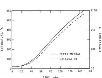
Accuracy of prediction of steel temperatures is illustrated in Figs. 3 to 5, where calculated results are compared with experimental results for a number of steel sizes and pro- tecting materials. In Figs. 3 and 4, measured and calculated temperatures are compared for protected steel exposed to heating in accordance with the standard temperature-time relation specified in ASTM E119.l In Fig. 5, the com- parison is for a steel member exposed to heating according to a temperature-time curve that more closely resembles an actual fire temperature curve. The graphs indicate that
---
CALCULATED-
0 I I I 1 I I I 3 7
TIME. rnin
Fig. 3. Steel temperature as a function oftime (size steel core:
6 in. X 6 in.; insulation ojinsulatingfire brick)
in the prediction of steel temperatures an accuracy of the order of 10 to 15 percent can be obtained, and this is ade- quate for practical purposes.
In investigating the influence of the various factors that determine fire rektance of protected steel members, hy- pothetical values were used for the material properties of the protection. Two sets of extreme values were selected to cover the wide range of properties of commonly used pro- tecting materials, one set representing the thermal prop- erties of a light insulating material of low conductivity and the other representing those of a heavy, more conductive material. The assumed volumetric specific heat and thermal conductivity of these materials were, respectively, 7.5 Btu/fQ°F and 0.1 15 Btu/ft h ° F for the lighter material, and 30 Btu/ft3"F and 0.7 Btu/ft h ° F for the heavier ma- terial.
In addition to dependence on the thermal properties of the protection, fire resistance also depends on the
I ,
---.
.
F U R N A C E \ - T E M P E R A I U R L \.
TIME. m i n \ STEEL-
L\.
T E M P E R A T U R E - i l O O';
,--'t---- P 3 +Fig. 5 . Steel and furnace temperature as a function of time (size steel core: 10 in. X 10 in.; insulation of vermiculite
board) \. -
\.
\ - E X P E R I M E N T A L - - 1 Ithickness of the protection and the size and shape of the steel. It has been shown12 that the influence of the size and shape of the steel and that of the thickness of the protection can be taken into account by one combined factor, ML/A, where 4 P 750 =: 5 d
-
600 37M = mass of the steel section per unit length
A = area of the protection at the interface between protection and steel through which heat is trans- ferred to the steel, per unit length
1 = thickness of the protection
P 20 40 6 U 80 100 120 140 160
In general, the fire resistance of a protected steel member increases with this factor, since a higher factor means more mass (M) of the steel to be heated, thicker protection (l), or less area (A) through which heat can be transferred to the steel. How this factor affects the fire performance of a steel member will be examined further for various practical conditions.
CALCULATION OF CRITICAL FIRE LOAD
Figures 6 to 8 show the calculated critical fire loads for the two selected protecting materials as a function of Ml/A for various opening factors and thicknesses of protection. It may be seen that the critical fire load increases as the opening factor increases, and that the increase is more pronounced for the higher opening factors. Inrrexse of the critical fire load with opening factor means that the probability of
failure of a protected steel member decreases with in- creasing opening factor of the building. T h i s indicates that less fire resistance is required in buildings with a high opening factor than in buildings with a small opening factor.
The influence of the thickness of protection on the critical
0
Q 20 40 6 0 80 l o o 120 140 160 fire load is also strong. It is relatively more pronounced for TIME, m i n low values of Ml/A, and affects the critical fire load in two
ways: in Figs. 6 to 8, the critical fire load varies not only
Fig. 4. Steel temperature as a function of time (size steel core: with the factor Ml/A (which comprises the thickness of the
Table 1. Range of Values of Variables Investigated
Variable Range
Opening factor Mass of steel Heated area of steel Thickness of protection
Thermal conductivity of protection Volumetric heat capacity of protection
0.036-0.18 ft1I2 33-1075 Ib/ft length 3.3-13 ft2/ft length 0.4-1.6 in. 0.1 15-0.7 Btu/ft h "F 7.5-30 Btu/ft3 "F
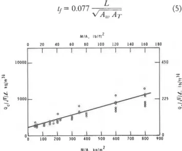
in practice, the relation shown in Figs. 9 and 10 of critical fire load and the factors that determine it can be given by an equation of the form
where K3 and K4 are coefficients that depend on the ther- mal properties of the protection.
It is possible to derive for a particular protecting material, as for the two protecting materials selected in this study, the equation for critical fire load, if the thermal properties of the material are known. Often this is not the case and the only way to determine the critical fire load is by testing.
RELATION OF CRITICAL FIRE LOAD TO STANDARD FIRE RESISTANCE
Tests are usually carried out by subjecting a specimen to heating according to a standard temperature-time curve until it The time to failure, known as the standard fire resistance, is determined during the test and used as a relative measure for the fire performance of the member. The standard fire resistance, however, does not give direct information on the critical fire load. T o be able to express the fire performance of the member in tenns of the critical fire load, the relation between the standard fire resistance and critical fire load must be known.
At present, empirical relations exist between fire load and the severity of fire it produces, expressed in terms of duration of exposure to the standard fire. Ingberg6 found from experiments that a fire load of 10 lb/ft2 floor area produces a fire with a severity approximately equivalent to that of a standard fire of 1-h duration; that 20 lb/ft2 is equivalent to 2 h; 30 lb/ft2 to 3 h; 40 lb/ft2 to 4'12 h; and 60 lb/ft2 to 7.5 h. Thus, according to Ingberg, fire severity increases directly with fire load for the first 3 h. After that the relation between fire severity and fire load is linear, with a different slope.
This relation does not take into account the effect of ventilation on fire severity. It was examined in later studies by Law,8 who introduced the following relation of fire se- verity, fire load, and ventilation:
where
M I A . l b l f t 2
Fig. 9. Relation offactors that determine the fire resistance of protected steel (light protection)
t j = fire severity expressed as duration of exposure to a standard fire
L = total fire load
A, = area of the openings in the room
AT = total bounding surface area of the room H = height of the openings in the room
C = a coefficient
Based on the results of a large number of experimental fires, Law derived that for protected steel Eq. (4) can be given as
MIA, l b 1 f t 2
[
2; 4,O 6,O 8; l:O :1 1;O 16; 18;Fig. 10. Relation offactors that determine the fire resistance of protected steel (heavy protection)
120 ENGINEERING JOURNAL I AMERICAN INSTITUTE OF STEEL CONSTRUCTION
In this derivation, it was assumed that the critical tem- perature of steel is 1020°F, and that the influence of win- dow height H is so small that it can be neglected. A relation similar to Eq. (4) was used by Pettersson,16 based on a critical steel temperature of 930" F.
In the present study, the relation of fire load, ventilation, and fire severity is derived theoretically, using as a basis the heat and mass transfer equations that determine the tem- perature history in the fire compartment and in the steel member exposed to the fire. These equations are described in detail in Refs. 7,9, 11, and will not be given here; only the results will be presented.
Values for a large number of calculations are shown in Fig. 11, covering a range of conditions normally met in practice with regard to opening factor, steel shapes and sizes, thermal properties of the protecting materials, and their thicknesses (Table 1). A critical steel temperature of 1000°F was chosen, which is the critical temperature specified in ASTM E l 19, implying that in this case fire severity is defined as the duration of exposure to the ASTM E l 19 standard fire required to raise the steel temperature to the critical value of 1000°F.
W I N D O W H G H ( 9 . 9
//A
1 1 1 h * 0 1 m 1 3 . 3 f l ) 5-
-
a-
-
0 C A L C U L A T E D - L A W ' S R E L A T I O NFig. 7 7. Comparison of Law's relation with calculated values
In Fi 11, the fire severity has been plotted as a function of Q/
3
F , whereQ
is the fire load per unit bounding surface area of the room and F is the opening factor. The quantityQJTF
has been selected as a parameter because it is also the quantity that determines the fire severity t j in Law's Eq. (4), which can be transformed to the form1
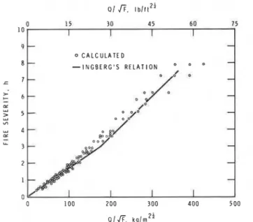
0 C A L C U L A T E DFig. 72. Comparison of Ingberg's relation with calculated values
For comparison, Law's relation [Eq. (S)] has been plotted in Fig. 11. As the window height does not appear in this relation, it was modified to
and tj evaluated for three values of window height H: 3.3 ft, 6.6 ft, and 9.9 ft. It may be seen that for a window height of about 6.6 ft there is good agreement between calculated and experimental results. For greater heights the calculated fire severities are, on the average, somewhat lower than the experimental fire resistances. For smaller heights, calcu- lated fire severities are somewhat higher than the experi- mental values. As expected, however, the influence of window height on fire severity is relatively small from a practical point of view.
Figure 12 compares calculated fire severities with those given by the Ingberg relation. Unfortunately, accurate information on the opening factor F for Ingberg's tests is not available. It is possible, however, to estimate it by as- suming that Ingberg's relation is a particular case of Law's more general relation, given by Eq. (7). In this case there is a certain value of the opening factor for which both relations are identical. Substituting in Eq. (7) the value of
Q in Ingberg's experiment (2.7 lb/ft2 bounding surface area of the room for each hour fire d ~ r a t i o n ) ~ > ~ ~ and H =
5 ft, gives for the opening factor the value F = 0.1 ft1/2. Analysis of the available information on the test room used by Ingberg and the test results indicated that this is a reasonable value for the opening factor. According to ex- isting information the window area was 84 ft2 during the tests. As the bounding surface area of the test room was 1600 ft2, the opening factor would be 0.11 7. In Ingberg's
121
experiment, however, the windows were partially closed, so that the opening factor was lower than 0.1 17. On the other hand, the temperatures reached in the room were higher than those of the standard fire temperature curve and indicate that the opening factor must have been more than, for example, 0.07. It would not have been possible, otherwise, to produce in a concrete enclosure the temper- atures measured during the test. Using an opening factor of F = 0.1 ft1/2, it may be seen in Fig. 12 that there is a good agreement between the Ingberg relation and the calculated values.
T h e comparisons indicate that there is reasonable agreement between the experimental and calculated rela- tions of fire load and fire severity. Using these relations as a basis, it is possible to develop for protected steel members a correlation between the critical fire load under practical conditions and the fire resistance under standard test con- ditions. In actual practice, however, many more factors affect both fire severity and fire resistance than those taken into account so far; for example, fire severity is affected by fire load surface area;fire load arrangement, wind, and the properties of the walls of the fire compartment; fire resis- tance is affected by structural load, restraint, slenderness of columns, and actual thickness of protection, which often differs from that specified. Their influence may be sub- stantial. They may, for example, cause deviations of the order of 50 percent from the predicted fire severity or fire resistance. In comparison with the influence of the two most important factors, fire load and opening factor, that can have values, in practice, in a range extending over a factor of 10, their influence is relatively small. It is justifiable, therefore, to express the correlation between critical fire load and fire resistance only in terms of the most important factors, and to take into account the influence of the other factors, which are often unpredictable and uncontrollable, by incorporating an appropriate factor of safety in the fire resistance requirements.
The following general correlation formula, expressing the relation of fire load, standard fire resistance, and opening factor, is suggested
where R is the standard fire resistance (hours) required to resist burn-out of a fire load
Q
(lb/sq ft bounding area) in a compartment with an opening factor F (ft1I2).If the standard fire resistance of a steel member is known, the critical fire load can be derived using this equation. The critical fire load
Q
,
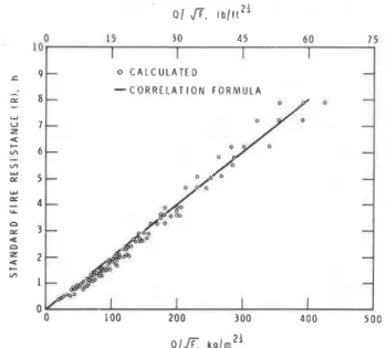
is given byIn Fig. 13, Eq. (8) is compared with calculated values. The comparison indicates that Eqs. (8) and (9) may be applied with good confidence in the 1- to 4-h range, the range in which most fire resistance problems of practical significance lie.
Q / fi, l b / f t 2 '
0 15 30 4 5 60 7 5
1 a I I I I 0 C A L C U L A T E D
Fig. 13. Comparison of suggested correlation formula with calculated values
The somewhat higher standard fire resistances given by Eq. (8), in comparison with calculated values, also permit its use, along with Eq. (9), for protection thicknesses greater than the maximum thickness of 1.6 in. investigated. As can be seen in Figs. 14 to 16, the standard fire resistance re- quired to withstand burn-out of a specific fire load increases slightly if the thickness of the protection is increased. Al- though the range of opening factors investigated, i.e., 0.036 to 0.18 ft'/2, will normally cover those met in practice, Eqs. (8) and (9) may also be used for extremely small or for large opening factors. As can be shown by replotting the data in Figs. 14 to 16, the results will lie on the safe side in these cases.
APPLICATION O F CORRELATION FORMULAS It is possible to determine the critical fire load for a member directly by solving the basic heat and mass transfer equa- tions for the fire in the compartment and the fire-exposed steel member. The method, however, is complicated and requires a fast computer and knowledge of the thermal properties of the protection, which is, at present, often in- adequate. At this stage, therefore, the method is not very suitable, although in the future it might be the shortest way to determine the fire performance of structural mem- bers.
A more practical method of determining the critical fire load of a member is to determine the standard fire resistance of the member and convert it to critical fire load, using the correlation formulas. This method is particularly useful because there is a large amount of information on the standard fire resistance of protected steel and many facilities available for determining it.
C R I T I C A L F l R E L O A D I Q c l , l b l f t 2 C R l T l C A L F l R E L O A D (Ocl, l b 1 f 1 2
C R I T I C A L F l R E L O A D ( P C ) k g l m 2
Fig. 74. Relation of standard fire resistance (R) and critical
fire load ( Q ,) for an opening factor F = 0.036ft
In the following, examples will be given of the use of correlation formulas for fire resistance design of steel members. A 10-story office building of average size will be considered. Each story may be regarded as a fire-resisting compartment. From data of fire load
survey^,^
it can be derived that the mean fire load in each story of an officeC R I T I C A L F l R E L O A D IQ,). I b l f t 2
1
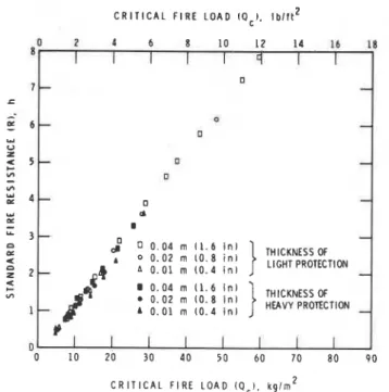
Fig. 75. Relation of standardfire resistance ( R ) and criticalfire load ( Q J for an opening factor F = 0.09ji'/2
Fig. 76. Relation of standard fire resistance ( R ) and critical
fire load ( Q ,) for an opening factor F = 0.78ft
building is about 2 Ib/ft2 bounding area. A typical fire load safety factor for a 10-story building of average size is 2.1° Assuming that this safety factor also applies to the building under consideration, the design fire load can be put at 4 Ib/ft2 bounding surface area.
Example 1
Given:
Floor area of story: 160 X 160 ft Height of story: 10 ft
Window area: 2000 ft2 Window height: 5 ft
The task is to determine the fire resistance required to withstand burn-out of the design fire load.
Solution:
According to Eq. (8), the standard fire resistance R re- quired to withstand burn-out of a fire load
Q
iswhere
Using the given information, it can be derived that:
Substituting values of AT, A,, and H for the opening factor gives:
123
Substituting values of F and
Q
in Eq. (8) for the fire re- 1. There is approximate agreement of computed results sistance gives: with Ingberg's experimental relation for fire load and 4 fire severity, and with that of Law for fire load, fire R =0.13-=dm%
1 . 9 h severity, and ventilation.2. It is possible to develop simple design formulas for Thus, for the building under consideration a standard fire
the calculation of the performance of protected steel resistance of 1.9 h is adequate to withstand burn-out of the
design fire load. members under standard fire test conditions, as well as in natural fires.
Example 2-One method of determining the standard fire 3. The severity of standard test fires can be related to resistance of structural members in the building is by those met with in practice using the equation R =
testing. For various protecting materials, however, the 0.13
Q/G
,
where R is the standard fire resistance, relation between the standard fire resistance of a memberQ
the fire load per unit bounding surface area of the and the factors that determine it is known. In such cases the compartment, and F the opening factor.conditions, for example, the thickness of protection to obtain
the required fire resistance, can be determined by calcu- 4. The fire load that a member can resist in a burn-out lation. In the following, an example will be given of the fire, i.e., the critical fire load, is proportional to the method of calculation of the required thickness for columns standard fire resistance of the member and to the protected by a specific protection. square root of the opening factor of the compart-
ment.
Given: 5. Both the critical fire load and the standard fire re-
In this example it will be assumed that the building is sistance increase directly with the thickness of the supported by W-type steel columns, and that they are protection and linearly with the size and shape factor, protected by a box type encasing of vermiculite board. The M/A, of the steel.
size of the cross section of the column is 1 ft X 1 ft and the
mass of the steel is 160 lb/ft length. ACKNOWLEDGMENT
The author wishes to thank D. W. Morwick for computing
Solution:
the various quantities used in this study. For the protection under consideration it has been estab-
This paper is a contribution from the Division of lishedl29l7 that the standard fire resistance of a column
Building Research, National Research Council of Canada protected this is given a ~ ~ r o x i m a t e l ~ the and is published the of the Director of the relation
Division. R =
( " )
0 . 7 5 - + 6 1A (10) REFERENCES
In this example, the values of R, M , and A are, respec- 1. American Society for Testing and Materials Fire Tests of
tivel y: Building Construction and Materials Designation E 1 19- 73,
Part 78 of ASTM Book of Standards.
R = 1 . 9 h 2. Fire and Live Loads in Buildings Committee on Fire and
M = 160 lb/ft column length Liue Loads in Buildings oofthe Building Research Aduiso y
A = 4 X 1 = 4 ft2/ft column length Board, National Academy of Sciences, Washington, 1977.
3. Fire-Resistance Tests-Elements of Building Construction
Substituting these values in Eq. (10) and rearranging International Standard I S 0 834, International Organization
gives: for Standardization, 7975.
4. Gross, D. Experiments on the Burning of Cross Piles of
1 = 0.053 ft Wood J. Res. Natl. Bureau Stds., 66C, 99, 1962.
5. Harmathy, T . Z. A New Look at Compartment Fires, Part
or
I and Part I1 Fire Technology, Vol. 8, No. 3 and 4, 1972.
1 = 0.64 in. 6. Ingberg, S. H. Tests of the Severity of Building Fires NFPA Quarterly, Vol. 22, 7928.
Thus, a protection of 0.64 in. thickness will provide the 7. Kawagoe, K. and T . Sekine. Estimation of Fire Tempera- desired fire resistance. ture-Time Curve in Rooms Building Research Institute, Ministry of Construction, Tokyo, Occasional Report No. 11,
CONCLUSIONS 7963.
8. Law, M . A Relationship between Fire Grading and
With an accuracy adequate for practical purposes, the Building Design and Contents Joint Fire Research Orga- following conclusions may be drawn regarding protected nization, Borehamwood, Herts, Fire Research Note 877,
steel members: 7971.
124
9. Lie, T . T . Characteristic Temperature Curves for Various Fire Severities Fire Technology, Vol. 10, No. 4, 1974.
10. Lie, T. T . Optimum Fire Resistance of Structures Journal
ofthe Structural Division, ASCE, Vol. 93, No. ST1, Proc. Paper 8638, 7972.
1 1 . Lie, T . T . Temperature Distributions in Fire-Exposed Building Columns Journal ofHeat Transfer, Trans. ASME, Series C, Vol. 99, No. 1, 1977.
12. Lie, T. T. and W. W. Stanzak Fire Resistance of Protected Steel Columns Engineering Journal, AISC, Vol. 10, No. 3. 7973.
13. ~ i e , T . T . and W. W . Stanzak Structural Steel and
Fire-More Realistic Analysis Engineering Journal, AISC,
Vol. 73, No. 2, 7976.
14. Magnusson, S. E. and S. Thelandersson Temperature-
Time Curves of Complete Process of Fire Development; Theoretical Study of Wood Fuel Fires ih Enclosed Spaces Acta Polytechnica Scandinavia, Stockholm, Civil Engi- neering and Building Construction Series No. 65, 1970. 15. Odeen, K. Theoretical Study of Fire Characteristics in
Enclosed Spaces Royal Institute of Technology, Stockholm,
Division of Building Construction, Bulletin 70, 7963.
16. Pettersson, 0. The Connection between a Real Fire Ex-
posure and the Heating Conditions According to Standard Fire Endurance Tests with Special Application to Steel Members Fire Safety in Constructional Steelwork, Euro- pean Conuention for Constructional Steelwork, CECM- 111- 74-2E, Chapter 11, 7977.
17. Stanzak, W. W. and T . T . Lie Fire Tests on Protected Steel
Columns with Different Cross-Sections National Research Council of Canada, Division of Building Research, NRCC
13072, 1973.
18. Thomas, P. H. The Fire Resistance Required to Survive
a Burnout Joint Fire Research Organization, Boreham- wood, Herts, Fire Research Note 901, 7970.
19. Thomas, P. H., A. J. M . Heselden, and M. Law Fully-
Developed Compartment Fires; Two Kinds of Behaviour
H. M. Stationery Office, London, Fire Research Technical
Paper No. 15, 1967.
20. Tsuchiya, Y. and K. Sumi Computation of the Behaviour of Fire in an Enclosure Combustion and Flame, Vol. 16,
This publication is being distributed by the Division of Building Re- search of the National Research Council of Canada. It should not be reproduced in whole or in part without permission of the original pub- lisher. The Division would be glad to be of assistance in obtaining such permission.
Publications of the Division may be obtained by mailing the appro- priate remittance (a Bank, Express, or Post Office Money Order, or a cheque, made payable to the Receiver General of Canada, credit NRC) to the National Research Council of Canada, Ottawa. KIA 0R6. Stamps are not acceptable.
A list of all publications of the Division is available and may be ob- tained from the Publications Section, Division of Building Research, National Research Council of Canada, Ottawa. K I A OR6.