Publisher’s version / Version de l'éditeur:
Vous avez des questions? Nous pouvons vous aider. Pour communiquer directement avec un auteur, consultez la première page de la revue dans laquelle son article a été publié afin de trouver ses coordonnées. Si vous n’arrivez pas à les repérer, communiquez avec nous à [email protected].
Questions? Contact the NRC Publications Archive team at
[email protected]. If you wish to email the authors directly, please see the first page of the publication for their contact information.
https://publications-cnrc.canada.ca/fra/droits
L’accès à ce site Web et l’utilisation de son contenu sont assujettis aux conditions présentées dans le site LISEZ CES CONDITIONS ATTENTIVEMENT AVANT D’UTILISER CE SITE WEB.
Society of Naval Architects and Marine Engineers, World Maritime Technology
Conference and Exposition, San Francisco 2003 [Proceedings], 2003
READ THESE TERMS AND CONDITIONS CAREFULLY BEFORE USING THIS WEBSITE. https://nrc-publications.canada.ca/eng/copyright
NRC Publications Archive Record / Notice des Archives des publications du CNRC :
https://nrc-publications.canada.ca/eng/view/object/?id=3974e6a1-406b-43b8-95b7-69b9e0fa59d1
https://publications-cnrc.canada.ca/fra/voir/objet/?id=3974e6a1-406b-43b8-95b7-69b9e0fa59d1
NRC Publications Archive
Archives des publications du CNRC
This publication could be one of several versions: author’s original, accepted manuscript or the publisher’s version. / La version de cette publication peut être l’une des suivantes : la version prépublication de l’auteur, la version acceptée du manuscrit ou la version de l’éditeur.
Access and use of this website and the material on it are subject to the Terms and Conditions set forth at
A flat wave-piercing bow concept for high speed monohulls
A FLAT WAVE PIERCING BOW CONCEPT FOR HIGH
SPEED MONOHULL
Peter van Diepen
1, David Molyneux
2, Gabriel Tam
3ABSTRACT
High-speed monohulls are known to experience excessive motions and structural loads caused by accelerations and slamming when operating in heavy weather. This paper presents a concept of a new wave-piercing bow designed to reduce adverse motions and structural loads. That goal has been achieved by introduction of a bow form that features upper surfaces shaped to generate downward lifting forces, which counterbalance the displacement forces that lift the bow up while moving through a wave and initiate pitching motion; counterbalancing these forces stabilizes the hull. Extensive model testing has been carried out on several models between December 2000 and March 2002. Resistance forces, accelerations and bow pressures were recorded and used to define critical loading cases, subsequently used in a global finite element analysis of the structural arrangement of a generic 165ft Gulf of Mexico crew boat, its scantlings determined using direct approach under ABS High Speed Craft Guide. The research indicated a potential for significant reduction of motions, structural loads, scantlings, structural weight and power requirements.
1NaviForm Consulting & Research Ltd, Vancouver, B.C., Canada
2National Research Council Canada - Institute for Marine Dynamics, St.John’s, Nfld, Canada
INTRODUCTION
This paper outlines the Research & Development program of a new concept of a high-speed wave piercing monohull. The program was carried out between September 2000 and September 2002 by NaviForm Consulting & Research Ltd (NaviForm) of Vancouver, Canada, in cooperation with the National Research Council Canada’s (NRC) Industrial Research Assistance Program (IRAP) and Institute for Marine Dynamics (IMD) in St. John’s, Canada, and TAG-Aerospace (TAG) of Delta, Canada. The American Bureau of Shipping (ABS) participated in this program as an external technical advisor offering technical guidance on design analysis approaches and requirements with respect to the classification of the vessel design. The concept was expected to address problems caused by motions of a standard monohull at speed in waves: motions that affect crew and passengers, as well as the weight of a craft, caused by the heavy scantlings required to compensate for high structural loads.
In the distant past, ocean-going ships operated at relatively low speeds, and crew and passengers had to put up with motions in waves. Later, adverse motions were mitigated, to some extent, by increased hull lengths. However, with the advent of high-speed marine transportation, motions, especially accelerations, have become an increasingly serious problem. Weight is the enemy of speed, and heavy scantlings, which did not affect the power at lower speeds to such a degree, are these days subject to an ongoing effort of designers to minimize them, while the authorities that safeguard safety of ship design have to ensure that safety is not compromised. Passengers are no longer willing to simply tolerate adverse motions.
The last thirty years have brought significant developments in the area of motion control of ships in heavy seas. These developments broadly fall into two categories: passive and active. Active ride control devices rely primarily on generating forces to oppose the exciting forces. This is often achieved through the introduction of articulated, computer controlled fins, mounted on the hull or pods, or transom mounted articulated ride control flaps. Motion control can also be achieved by shifting weights, for example, liquids in antiroll tanks. While often referred to as passive antiroll devices, for the purpose of this discussion let us put them in the category of active, if not necessarily powered, motion control devices.
By this definition, passive means of controlling hull motions in waves have been primarily addressed by improvements to the hull form. The great
Australian invention of wave piercing bows in catamarans, which had to operate in heavy seas around the Australian South Coast, has revolutionalized the design of high-speed ferries. It is important for this discussion to briefly highlight the Australian wave piercing catamaran concept, as it
was, in a sense, a catalyst for the concept we are
presenting. In wave piercing catamarans, instead of the traditional tall raked stems, the bows feature very sharp stems barely emerging from the water at the operating draft. They effectively pierce the waves, and prevent initiation of upwards movement and pitching motions, but this action does create a new problem. Without the reserve buoyancy of traditional bows, the hulls would dive too easily into the wave trough. In catamarans, this problem was addressed by fitting a third, centerline bow, typically above the waterline, to control the diving movement.
This technology works well, and it is often combined with active ride control devices to further optimize the ride in heavy seas. Its application, however, was limited to multihulls, leaving monohulls without a solution. Finding a similar solution for fast monohulls has become increasingly important, as their speed grew and their operational envelope continued to expand.
There has been a substantial research effort carried out in recent years, primarily in Europe, on motion control of monohulls through modification of their hull forms. These efforts have led primarily to the introduction of very long narrow bows. Not having been involved in such research, the authors can only assume that the basic goal was to design a hull form that would minimize variable vertical forces generated at speed through waves. Initiation of the pitching motions would be minimized by
adopting small, elliptical cross-sections of the bow
that would react to waves as little as possible. This conclusion is supported by the specification of U.S. Patent No. 6,116,180 by Thompson, who designed a prototype that was extensively tested in the U.K. The Australian pedigree is obvious, but without the third bow. The use of ever longer bows may have improved the motions, but the long bows are not practical for several reasons, and so far they have not found their way into commercial or naval applications.
All these considerations have defined the problem, which the research we are presenting, was supposed to address.
DESIGN DEVELOPMENT
The concept discussed in this paper originated with several requests for proposals involving
high-speed monohulls carrying payload in heavy seas. The most commonly requested proposals were for Gulf of Mexico crew boats. Crew boats have been operating for many years, and often have been found to be very uncomfortable by passengers. So much so, that crew boat operation in the Gulf of Mexico is limited to Sea State 5, or 11ft waves. In fact, the loads defined in the HSC Guide are derived from the accelerations and structural loads empirically determined for operation in 11ft waves.
In developing the potential solution, it was important to consider the primary factors inducing the accelerations and slamming, and to consider innovative methods for reducing or eliminating them. Such an approach was believed to represent a better prospect for business development than trying to incrementally improve upon the existing design solutions.
One of the most important aspects for ship performance is the weight of a craft. It is the key to high-speed performance, for no matter how hydrodynamically effective a hull form is, the displacement remains an important factor affecting power requirements and the economics of operation. The two most important factors contributing to the weight of a hull are its overall size and its scantlings. The former led the design team away from the concept of long slender bows, for no matter how light they are made, their sheer length makes them heavy. The latter led us to an in-depth investigation of the factors affecting the scantlings of a high-speed vessel, highlighting once again the importance of limiting hull length, reducing accelerations, and eliminating slamming loads.
With this conclusion in mind, we set out to investigate the possibility of stabilizing a high speed vessel’s bow in waves, without increasing its length. From the outset, it had become apparent that to prevent buoyancy forces from lifting the bow up when moving through a wave, a device would be needed that would generate dynamic lifting forces opposing those upward forces. One obvious choice would have been an inverted foil, in a possible form of fins fitted to the bow above, but close to, the waterline. However, the initial numerical analysis indicated that a typical bow form generates forces far exceeding any downforce that could be created by a fixed foil with a span not extending beyond the hull envelope, no matter how long such foil would be.
This reasoning led to the creation of an initial form of the bow taken to NRC to seek their support of our research: a form that was a compromise of shaping the bow much like a flat chisel, to balance its movement through the waves by both removing the excess of volume above waterline and using the hollow to create surfaces that would generate
downward lifting forces opposing the displacement forces in waves. This approach also enabled reduction of dependency on speed, so characteristic for a fixed foil. The longer and sloping top surfaces could be shaped to match the distribution of displacement force along the hull, which can be calculated numerically, with the distribution of dynamic downforce, which can only be estimated, but with accuracy sufficient to reduce motions.
The initial testing program, the proof of concept, was carried out in October through December 2000, under a cooperation agreement with IRAP only. As part of this agreement, the goal was set beforehand at 25% reduction in motions; and NaviForm and IRAP agreed not to pursue the research further if that goal would not be reached.
The first model of a generic 200ft hull, in 1:20 scale, was tested at the British Columbia Research Institute (BCRI) in Vancouver, in 6ft and 10ft waves, with two interchangeable bows: a standard raked bow, and a flat wave piercing bow. Accelerations at the bow, the center of gravity, and the stern, pitch angle and added resistance, as well as video footage of the runs, were recorded. The results indicated a reduction of accelerations of up to 40%.
These results were encouraging and led NaviForm and IRAP to the decision to continue and expand the program. The initial research, however, highlighted a new problem. Not unexpectedly, there was a large quantity of green water and spray shipped over the flat, chisel shaped bow, onto the wheelhouse and the deck where the cargo would be present. This problem had to be addressed during the second phase of testing.
Organizing the second phase of testing, during which the wave piercing bow was to be optimized, proved to be a logistical challenge. The designers had satisfied themselves that the motions, and, likely, hull structural loads which were not measured during the initial proof-of-concept phase, could be reduced. However, in order to translate these observed savings into reduction of the scantlings, the program had to be expanded into the structural design area, under the supervision of a recognized Classification Society.
The National Research Council’s IRAP has been instrumental in bringing the team together. The Institute for Marine Dynamics was retained to carry out model testing, while TAG-Aerospace was contracted to carry out FE modeling and analysis. ABS provided direction in terms of the requirements to be addressed by the model experiments, the analysis of the model test results, the selection of critical loading conditions, and evaluation of FE analysis results.
It is of interest to mention that many of the key personnel of our research team had a background in
aerospace design, not in hydrodynamics. Their influence on the team’s thinking was critical to the project’s success. It should be noted that the very essence of the phenomenon of a hull passing through water in time domain, rather than remaining in the boundary of water and air, brings the mechanics we are dealing with closer to the aerodynamics experience.
The second phase of the R&D program involved testing three versions of the wave piercing bow,
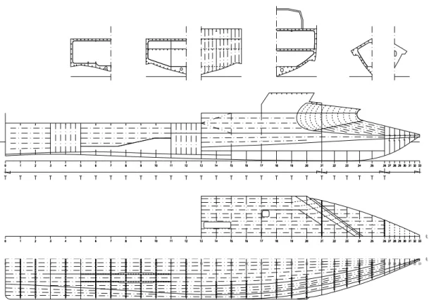
shown in Figures 1-3, against the same size hull of a standard Gulf of Mexico 165ft crew boat, shown in Figure 4, with the goal of determining the direct comparison of hull motions and loads, and optimizing the wave piercing bow. The program was completed in September 2002. The results presented in this paper indicate that indeed there is a potential to significantly reduce hull motions in waves, and to reduce lightship weight.
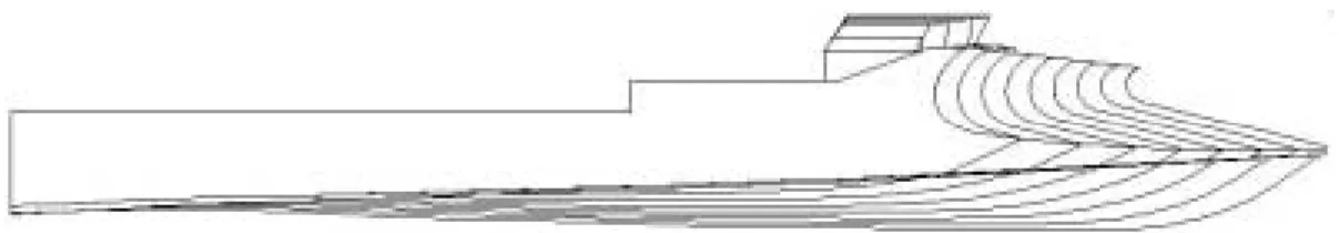
Figure 1: Profile and Buttock Lines of the Wave Piercing Hull - Bow A (Long)
Figure 2: Profile and Buttock Lines of the Wave Piercing Hull - Bow B (Short)
Figure 3: Profile and Buttock Lines of the Wave Piercing Hull - Bow C (“Duck Bill”)
MODEL TEST PROGRAM
A model test program was required to give a comparison of the performance of the wave-piercing hull against the crew boats currently in use. In order to satisfy budget constraints, it was proposed to tow the models rather than use working propulsion systems. It was recognized that this would affect the motions of the model, since an artificial constraint in surge was introduced. Also, any potential damping of the motions due to the flow around the propellers would be ignored. Since both concepts would be affected in the same way, the simplification was thought to be reasonable. Also, since the models were required to be tested at speeds up to the equivalent of 30 knots ship speed, head waves were the only condition that gave a sufficient number of wave encounters for practical evaluation of the concept. When dealing with extreme phenomena, it is generally accepted that 60 minutes of data is required for statistical purposes. The cost of collecting this amount of data for all hull form concepts was outside the program budget. However, it was reasoned that since the wave-piercing concept would only be considered successful if significant reductions in motions were observed, shorter run times would be acceptable for comparison purposes, provided comparisons were made on average values rather than extremes. To make the comparison valid, identical environmental conditions must be used for all models. This was achieved by using the same wave maker drive signals to create pseudo-random waves for the required run time. Irregular waves were chosen for design evaluation purposes, since time for testing was a critical factor, and irregular waves provided a realistic wave environment. As a result, probable non-linearities in the response of the wave-piercing hull with wave amplitude would not have to be considered.
A series of model experiments was carried out in the 200 m towing tank of the Institute for Marine Dynamics in St. John’s to support the development of the wave-piercing concept and its comparison with the conventional hull. The model test program was carried out in three phases. The first phase collected data on the conventional hull of a contemporary 165ft crew boat, for two displacements (see Figure 1). These corresponded to a light load condition, 400 tons and a deep load condition, 550 tons displacement. Three speeds (15, 22.5 and 30 knots) for each displacement were tested in irregular waves with a significant height of 3.35 m (11 ft). Waves were generated to match a JONSWAP spectrum, with a peak period of 7.1 seconds. A peak enhancement factor of 3.3 was used. This wave height is the one used to determine scantlings under the ABS High Speed Code. In addition, the light displacement was tested for three speeds (10, 15 and 20 knots) in irregular waves with a
significant height of 6.10 m (20 ft) and a peak period of 8.6 seconds, which represented a survival condition. Data was collected for 20 minutes equivalent full-scale time.
The second phase was the design development phase, which was used to refine the design of the wave-piercing hulls by studying the effect of variations of wave piercing bows on motions. The displacement of the wave-piercing hulls was the same as the conventional hull. For this phase, only the hull with wave-piercing bows was tested, and run times were cut to 10 minutes (equivalent full-scale). Only the light displacement was tested at speeds of 15 and 30 knots. Five wave piercing bows were developed under this phase, but only four were tested.
The third phase consisted of selecting one of the wave piercing hulls and completing the test matrix to compare with the conventional hull, with all runs at 20 minutes full scale. The design chosen was the wave-piercing hull with the long bow, deflectors and additional foredeck area.
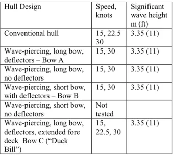
The model test matrix is given in Table 1. Shown in Figures 2-4 are the wave piercing hulls fitted with wave deflector. The short bow without deflectors was not tested, since there was found to be very little effect of foredeck length on motions, accelerations and loads. The full results of the model test program are described in [1 & 2].
Table 1: Test conditions discussed in paper
Hull Design Speed,
knots Significant wave height
m (ft)
Conventional hull 15, 22.5
30 3.35 (11)
Wave-piercing, long bow, deflectors – Bow A
15, 30 3.35 (11)
Wave-piercing, long bow,
no deflectors 15, 30 3.35 (11)
Wave-piercing, short bow,
with deflectors – Bow B 15, 30 3.35 (11)
Wave-piercing, short bow,
no deflectors Not tested
Wave-piercing, long bow, deflectors, extended fore deck Bow C (“Duck Bill”)
15,
22.5, 30 3.35 (11)
Models were constructed to a scale of 1:16. For the conventional crew boat a model of the hull, deck and superstructure was made. For the wave-piercing hull, a single stern section was built, and combined with two removable bows (one for each foredeck option). Further removable segments were included for the options with and without deflectors. Each wave-piercing hull was
also fitted with a representative deckhouse. Each model was ballasted to the correct scaled displacement and the nominal pitch radius of gyration (0.25 Lwl).
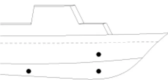
Each model was fitted with accelerometers at the bow, center of gravity and stern and six pressure transducers, in areas where hydrodynamic loads were important to the structural design. The positions for the wave-piercing hulls were at two locations in the lower panel, in areas where slamming loads were likely to be observed, and one location on the foredeck. For the conventional hull, the same two keel locations were used, and the third location was in the flare of the hull above the waterline. The locations of the pressure transducers and accelerometers are shown below.
Figure 5: Location of pressure transducers in conventional hull
Figure 6: Location of pressure transducers in wave-piercing hull
The pressure transducers were located on the port and starboard side of the hull to verify symmetry of the hydrodynamic pressures. In the case of the forward keel location, it was not possible to fit the transducers at exactly the same location, since the transducer crossed the internal centerline of the hull and so the transducers were staggered but as close to each other as practical.
In addition to the sensors in the model, there were two wave probes used to record wave data during the experiments. One probe was fixed to the side of the tank, 80 m away from the wave maker. The other probe was fixed to the tow carriage, on the starboard side of the model, ahead of the center of gravity. In this location, it did not interfere with the waves encountered by the model.
Data were collected for each of the parameters listed in Table 2. Summary statistics for each channel were calculated (mean, standard deviation, maximum and minimum) for each segment, as well as a zero-crossing analysis to determine the average of the 1/10 highest peaks (crest to trough) for motions and accelerations and maximum values (crest to trough) for pressures. A summary of the analysis procedures is also given in Table 2.
Table 2: Data collection and analysis during experiments
Description Sample Rate Hz
Analysis
Carriage speed 50 mean
Tow force 50 mean
Wave height (fixed in tank) 50 Average 1/10 highest
Wave height (encountered) 50
Average 1/10 highest
Heave at CG 50 Average 1/10 highest
Pitch 50 Average
1/10 highest Acceleration (bow, LCG,
stern) fixed in ship axis 50 Average 1/10 highest
Pressures at hull surface, 3
locations, port and starboard 500
Average Maximum The data for all channels was scaled to ship dimensions using Froude scaling. The incident wave, measured ahead of the model was corrected to the location of the tow post (at the model’s center of gravity) using Fast Fourier Transform (FFT) techniques to calculate the phase shift for each frequency component. Each channel was plotted in the time domain, and summary statistics determined, which included minimum, maximum, mean and standard deviation.
Video records were made of the experiments, from three views of the model. The first covered the port side of the model in full profile, and could be used to track spray trajectories. The second view covered the bow area in close-up, to observe relative motion and any wave impacts. The third view was from inside the wheelhouse, looking forwards through the wheelhouse window. These records were used to estimate wave impacts with the deckhouse.
The performance parameter used to initially compare the results was the value of each of the parameters discussed above, averaged over all segments at the same combination of forward speed and
1.400 1.600 1.800 2.000 2.200 2.400 2.600 2.800 3.000 3.200 10.0 15.0 20.0 25.0 30.0 35.0
Ship speed, knots
H e av e, A v e. 1/1 0 h ig h e s t, m 4.00 5.00 6.00 7.00 8.00 9.00 10.00 11.00 12.00 10.0 15.0 20.0 25.0 30.0 35.0 Ship speed, knots
P it c h , A ve. 1/ 10 h ig h e s t, m 10.000 12.000 14.000 16.000 18.000 20.000 22.000 10.0 15.0 20.0 25.0 30.0 35.0 ship speed, knots
1/ 10 b o w a ccel e rat io n , m /sec ^ 2
significant wave height. In the case of the pressures, there was a further averaging by using the mean values of the port and starboard transducer at each location. In all cases, there was a high degree of symmetry between the port and starboard results for pressures at the same nominal location. The method was chosen for ease of calculation and reliability of results, in that it did not depend on a single value. Also, some of the measurements, such as accelerations and pressures, showed a high degree of asymmetry about the zero value, which led to the approach of using the magnitude of the response from trough to crest rather the more conventional approach of mean to peak or trough.
COMPARISON OF WAVE-PIERCING HULLS WITH CONVENTIONAL DESIGN
The recorded values of :
Average 1/10 highest heave Average 1/10 highest pitch
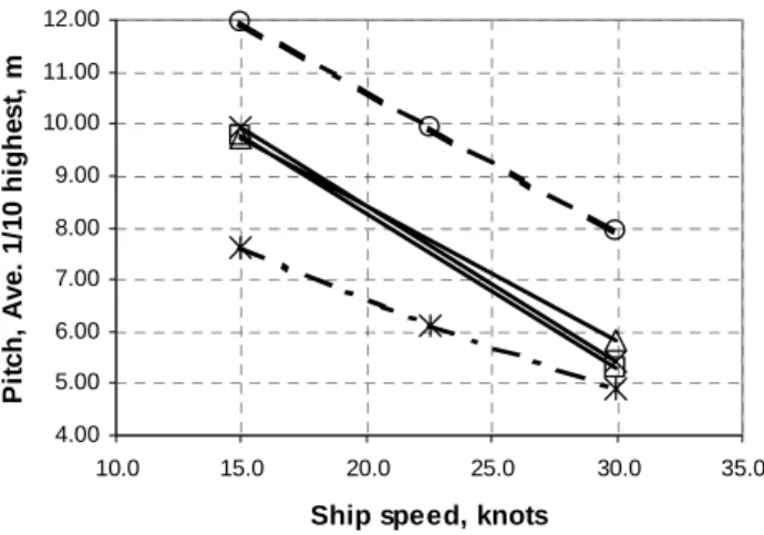
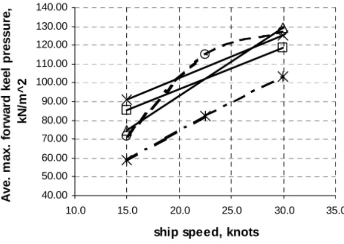
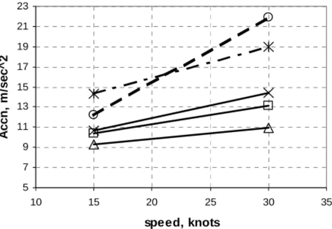
Average 1/10 highest acceleration at bow Average 1/10 highest acceleration at bow Average 1/10 highest acceleration at stern Average peak pressure at forward keel location are shown plotted against ship speed for all the ship concepts tested in Figures 7 to 12.
It should be pointed out that due to the cost and time constraints on the project, only two speeds were tested for many of the wave piercing concepts. To show all the results, straight lines have been fitted between these points. We noted that for the cases where we did have three data points for the wave-piercing hull the response was linear with ship speed, which was not the case for the conventional hull. Unlike the conventional hull, the wave piercing hull does not show any resonance with wave encounter frequency.
Legend for Figures 7 through 14:
Conventional hull O
Wave-piercing, long bow with deflectors ٱ
Wave-piercing, long bow without deflectors ∆
Wave-piercing, short bow with deflectors X
Wave-piercing, “duck bill” with deflectors !
Figure 7: Heave amplitude at CG, light displacement, 11ft (3.35m) waves
Figure 8: Pitch amplitude, light displacement, 11ft (3.35m) waves
Figure 9: Bow acceleration, light displacement, 11ft (3.35m) waves
5.000 10.000 15.000 20.000
10.0 15.0 20.0 25.0 30.0 35.0 ship speed, knots
1/ 10 CG ac cel e rati o n , m /s e c ^ 2 10.000 12.000 14.000 16.000 18.000 10.0 15.0 20.0 25.0 30.0 35.0
ship speed, knots
1/ 10 S ter n a ccel e ra ti o n , m /sec^ 2 40.00 50.00 60.00 70.00 80.00 90.00 100.00 110.00 120.00 130.00 140.00 10.0 15.0 20.0 25.0 30.0 35.0 ship speed, knots
A v e. m ax . f o rw ar d ke el p re ss u re, kN /m ^ 2
Figure 10. CG acceleration, light displacement, 11ft (3.35m) waves
Figure 11. Stern acceleration, light displacement, 11ft (3.35m) waves
Figure 12. Forward keel pressure, light displacement, 11ft (3.35m) waves
The first trend to notice is that for heave, pitch, acceleration at bow, acceleration at center of gravity and acceleration at stern, all the wave-piercing designs have lower responses than the conventional hull. Also, for heave and accelerations, there is little difference between the wave-piercing designs, so none of the detail design features are having an effect. The duckbill (Bow C) design has the lowest pitch value, so here the extra foredeck area is acting to lower the pitch response. For forward keel pressure, there is less difference between the wave-piercing designs and the conventional hulls, but the duckbill design has a lower response over the full speed range. On the basis of this simple analysis of the results, the wave-piercing designs show less excitation due to the waves, which was the basic reasoning behind the design.
Managing the water flow over the wave-piercing part of the hull is an important feature of the design. The video records were analyzed to count the number of wave impacts with the deckhouse. The number of events per hour was estimated from each 10-minute time limit for experiments. This is summarized below. Table 3. Wave impacts with wheelhouse, 3.35 m waves
Wheel house impact #/hour #/hour
Speed 15 kn 30 kn
Conventional 194 38
Wave piercing, long bow, with
deflector – Bow A 96 0
Wave piercing, long bow, no deflector 242 481
Wave piercing, short bow, with
deflector – Bow B 140 0
Duckbill – Bow C 96 0
The experiments at BCRI showed that the topsides were very wet in 10ft waves for the basic wave-piercing concept (without wave deflectors), and this was confirmed by the experiments at IMD. There were a very large number of wave impacts per hour, and almost every large wave resulted in an impact with the deckhouse. This created a lot of spray, as well as the potential for structural damage. Assessing the effect of the deflectors was one objective of this phase of experiments.
The deflector on the long wave-piercing bow worked well at reducing the number of wave impacts with the wheelhouse, especially at 30 knots, and as a result less spray was reaching the cargo deck. The deflector on the short wave piercing design was less effective, since the flow had more momentum when it hit the deflector, which gave an almost vertical trajectory to the spray. Whilst the number of wave impacts at 30 knots was not effected, there was much more spray around the hull.
5 7 9 11 13 15 17 19 21 23 10 15 20 25 30 35 speed, knots A ccn , m /sec ^ 2 40 50 60 70 80 90 100 110 120 130 140 10 15 20 25 30 speed, knots P res su re , K P a
Although the ‘duckbill’ concept was chosen for comparison with the conventional hull, one negative observation was that there was much more spray impact with the wheelhouse than for the equivalent conditions for the long wave piercing design with the deflector. In this case, the ‘duckbill’ tended to chisel off the top of the wave crest and scoop it up the foredeck.
For the finite element analysis data was required on the maximum structural load likely to be encountered, from the combination of inertia and hydrodynamic loads. Highest inertia loads were assumed to occur at the highest acceleration values, and highest hydrodynamic loads were assumed to occur at the peak pressure load. The preliminary analysis using the average 1/10 highest values was an attempt to determine a stable, meaningful index of performance. However, for the structural loads we had to determine the maximum values. In order to do this we developed a procedure that would allow us to check that the maximum value observed for accelerations and pressures was realistic. This was done by fitting Weibull probabilities to the observed data.
The probability density function for a Weibull distribution is − = − λ λ
σ
σ
σ
x x x f( ) 1 exp 1If the total number of observations of response events was n, and the events are ranked in order of severity, with 1 being the smallest and n being the largest, then the cumulative probability of each event is estimated by 1 ) ( + = n n x F i i
If the sample data can be plotted as a straight line in the form of
( )
−F xi 1 1 ln ln against ln(xi)then a Weibull distribution is a reasonable approximation to the data. This process was used to check the data, and in some cases, when the acceleration values had saturated, it was used to extrapolate to an estimate of the maximum value. In the case of observed saturation, the maximum observed
values (xi) stop increasing, even though the probability
continues to increase. Values above saturation were estimated by extrapolating the linear fit to the data below saturation. This process was checked against data
where no saturation was observed, and found to give estimated values within 5% of those actually observed.
Maximum bow acceleration and maximum keel pressure at the forward location are compared for all the hulls in Figures 13 and 14 for all hulls at the light draft. The results show that the designs are ranked in a different order, depending on whether pressures or accelerations are used. The duckbill design has low values of maximum pressure, but its acceleration values are larger than the conventional hull at 15 knots. The wave-piercing design, with no deflector has low pressures and accelerations, but other factors discussed above make this an impractical design. The best design from a structural loading point of view is the long wave-piercing design, with the deflector, since this has the second lowest maximum acceleration and maximum pressures that are lower than the conventional design. There seems to be little difference between the short wave-piercing design and the long design, if the deflectors are fitted.
Figure13: Maximum bow accelerations, 15 and 30 kn, light displacement, 11ft (3.35m) waves
Figure 14: Maximum pressure, keel fwd, 15 and 30 kn, light displacement, 11ft (3.35m) waves
conventional hull, 15 knots, wave elevation -3 -2 -1 0 1 2 3 300 350 400 450 500 550 600 tim e , s e c w ave e levat io n , m w ave elevation
conventional hull, 15 knots, bow accleration
-15 -10 -5 0 5 10 15 300 350 400 450 500 550 600 tim e accel er at io n at b o w , m/ s^ 2
bow accn corrd
wave-piercing hull, long bow, with deflectors, 15 knots, wave elevation
-2.5 -1.5 -0.5 0.5 1.5 2.5 250 300 350 400 450 500 tim e , s e c w av e el ev at io n, m w ave elevation
wave-piercing hull, long bow, with deflectors, 15 knots, bow accleration
-15 -10 -5 0 5 10 15 250 300 350 400 450 500 tim e ac cel er at io n at b o w , m/ s^ 2 bow accn
The acceleration responses are discussed in more detail below. The analysis initially carried out and discussed above was based on the need to develop a quick measure of the results during the test program, so that experiments could proceed with the most efficient use of tank time. In studying the results in more detail, it became apparent that there were some interesting features in the data, which did not show up during the relatively simple analysis. This was particularly related to the effect of the wave-piercing concept on measured accelerations.
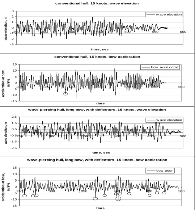
Figure 15 shows time histories of the bow acceleration for the conventional hull, and the
wave-piercing design with the long bow and deflectors for 15 knots in 3.35m waves. Also shown is the encountered wave elevation for each model. For the conventional hull we can see that the bow acceleration trace is typified as being mostly composed of accelerations with periods between peaks the same as those for the waves. However, at several locations there are very spiky responses (e.g. 385, 405 and 475 seconds) where the acceleration increases sharply, and then dies down to the level associated with the low frequency response. This is typical of a slamming response, where the relative velocity between the hull and the water surface is high enough to create an impact load on the hull.
Figure 15: Comparison of wave elevation and bow acceleration time histories for conventional hull and wave-piercing hull, long bow, with deflectors, 15 knots
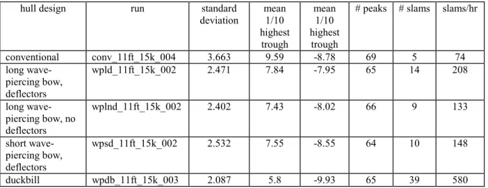
If we now compare this with the equivalent graph for the long wave-piercing bow, with the deflector, it can clearly be seen that the magnitude of the average acceleration peaks has dropped, but the number of slamming spikes has increased. This is summarized for all the models in Table 4, which gives the standard
deviation, mean of 1/10 highest peaks, mean of 1/10 highest troughs, number of peaks, and number of slams. It also includes an estimate of the number of slams per hour, based on the number of slams encountered in the run time.
Table 4: Summary of bow acceleration data, 15 knots, 3.35 m waves
hull design run standard
deviation mean 1/10 highest trough mean 1/10 highest trough
# peaks # slams slams/hr
conventional conv_11ft_15k_004 3.663 9.59 -8.78 69 5 74 long wave-piercing bow, deflectors wpld_11ft_15k_002 2.471 7.84 -7.95 65 14 208 long wave-piercing bow, no deflectors wplnd_11ft_15k_002 2.402 7.43 -8.02 66 9 133 short wave-piercing bow, deflectors wpsd_11ft_15k_002 2.532 7.55 -8.55 64 10 148 duckbill wpdb_11ft_15k_003 2.087 5.8 -9.93 65 39 580
From this table, it can be seen that the duckbill design has the lowest standard deviation, but it also has the highest degree of asymmetry between the peaks and troughs. The duckbill effectively damps out the peaks in the bow acceleration, but makes the troughs lower. It also increases the number of high frequency acceleration events dramatically, but the magnitude of these events is not much higher than the magnitude of the events for the conventional hull. This analysis was only carried out for 15 knots, since this was the condition that was most likely to be encountered.
It is clear that there is a trade-off taking place between the magnitudes of the low frequency wave induced motions and high frequency accelerations, likely occurring during slamming. So, whilst the wave piercing concepts tested as part of this project work well at damping out the low frequency acceleration, they do not necessarily reduce the slamming loads to the same extent. This is an area where more refinement of the design is required.
In order to evaluate all the models tested on a consistent basis, an index of performance was developed, which had an element of ride quality and structural load. The comfort of the ride for passengers and crew is often discussed as being effected by the standard deviation of a ship response in waves. This factor considers the ‘average’ deviation from the mean, and considers positive and negative values as being equally important. Motion sickness is particularly
dependent on the standard deviation of the acceleration at a given point in the hull and also the standard deviation of pitch. The US Navy has a standard for motion-induced sickness, which suggests that 20% of the crew will be sick if exposed to conditions where the pitch amplitude (RMS) exceeds 1.5 degrees and the
vertical acceleration (RMS) exceeds 0.2g (1.96 m/s2)
for four hours [3].
The four parameters chosen for ride quality in this analysis were the standard deviations of heave, pitch and bow acceleration, as well as the number of wave impacts with the deckhouse. The bow acceleration was chosen, since this was the highest value, and the passenger accommodation on these ships is well forward.
Two parameters were chosen for the structural loads index. In this case, the amplitude of the extreme value from the zero level is the most useful measure of response. The two parameters chosen were the maximum peak pressure at the forward keel location (based on the average of the port and starboard values) and the maximum amplitude of the bow acceleration. Each parameter was expressed relative to the conventional hull, which was assumed to have a value of 10. Tables 6 and 7 give a summary of the performance index for 15 and 30 knots respectively. This analysis assumed an equal weighting for each response parameter.
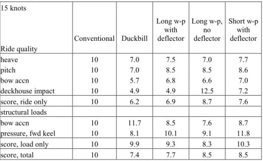
Table 6: Summary of Wave-piercing hull performance, 3.35 m waves 15 knots Conventional Duckbill Long w-p with deflector Long w-p, no deflector Short w-p with deflector Ride quality heave 10 7.0 7.5 7.0 7.7 pitch 10 7.0 8.5 8.5 8.6 bow accn 10 5.7 6.8 6.6 7.0 deckhouse impact 10 4.9 4.9 12.5 7.2
score, ride only 10 6.2 6.9 8.7 7.6
structural loads
bow accn 10 11.7 8.5 7.6 8.7
pressure, fwd keel 10 8.1 10.1 9.1 11.8
score, load only 10 9.9 9.3 8.3 10.3
score, total 10 7.4 7.7 8.5 8.5
Table 7: Summary of Wave-piercing hull performance, 3.35 m waves 30 knots Conventional Duckbill Long w-p with deflector Long w-p, no deflector Short w-p with deflector Ride quality heave 10 6.3 6.4 6.5 6.7 pitch 10 7.5 7.6 7.9 7.8 bow accn 10 5.7 6.7 7.0 7.1 deckhouse impact 10 0.0 0.0 126.8 0.0
score, ride only 10 4.9 5.2 37.1 5.4
structural loads
bow accn 10 8.7 6.0 5.0 6.6
pressure, fwd keel 10 8.3 9.6 7.3 9.7
score, load only 10 8.5 7.8 6.2 8.1
score, total 10 6.1 6.1 26.8 6.3
All of the wave-piercing hulls tested as part of this project show significant reductions in heave, pitch and acceleration when compared to a conventional hull (using the standard deviation of the response as the measure of performance). These reductions can be up to 40%, depending on the speed and sea state chosen. Based on an analysis of the combined responses of the hull that affect the quality of the ride and the loads on the structure, the duckbill bow has the best overall index of performance. The strength of this bow concept is in terms of its reduced motions (pitch heave and accelerations) relative to the conventional hull at speeds of 15 knots and 30
knots, in waves with a significant height of 3.35m. The extra width of the bow for the duckbill design is effectively damping out motions.
The most disappointing factor about the duckbill bow is that it does not have the best structural response index. This is obtained for the bow with no deflectors, but the number of wave impacts with the wheelhouse limits the practical application of this form of the piercing bow. Of the other wave-piercing bows, the long bow with deflectors has the best structural response index.
After the duckbill bow, the best overall response index was for the long wave-piercing bow with the
deflector, at speeds of 15 knots and 30 knots. At 30 knots, there was no difference in overall response index compared to the duckbill design.
Managing the water washing over the wave-piercing bow is a big factor in a successful design. Whilst low levels of deflection result in the lowest structural responses, the resulting hull has an impractically wet deck. The deflectors work well at moving water away from the wheelhouse, but increased water deflection also tends to increase the magnitude of the maximum acceleration, which increases the structural response index.
STRUCTURAL ANALYSIS
As important as the potential improvement in motions and their effect on passengers and cargo, is the assessment of the potential of translating the reduction in motions into the reduction in the hull
scantlings and the structural weight. In order to investigate this potential, a structural analysis of the concept wave-piercing monohull vessel is necessary. As a starting point, a generic wave-piercing crew boat was developed based on the scantlings of a contemporary Gulf of Mexico 165 ft crew boat with some allowance for standardization and simplification, as shown in Figure 16. A finite element coarse mesh model representing the full length of the generic monohull vessel was developed, as shown in Figure 17. Presented in Table 8 are the initial scantlings of the generic wave-piercing vessel in comparison with those typical of the contemporary crew boat design. As can be seen, the scantlings are generally lighter than those of the contemporary design. The objective of the structural analysis was to assess the overall level of stresses and to verify that the “lighter” scantlings are indeed possible.
Figure 17: Detail of FE model in the bow area
Table 8: Comparison of Scantlings of Existing Conventional and Wave Piercing Hull
Generic Wave Piercing Hull Existing Conventional Vessel
Shell plating, bottom fwd of Fr. 13 5/16” 1/2"
Shell plating, bottom aft of Fr. 13 1/4" 5/8”
Shell plating, side fwd of Fr. 13 5/16” 3/8”
Shell plating, side aft of Fr. 13 1/4" 3/8”
Deck plating, weather deck fwd of Fr.
13 5/16” 5/16”
Deck plating, cargo deck aft of Fr. 13 3/8” 3/8”
Deck plating, internal decks 1/4" 1/4"
Bulkhead plating 5/16” 5/16”
Deckhouse plating 3/16” 1/4"
Frames, deck transverses 9x5/16+3.5x3/8 6x4x5/16T
Longitudinal, deck stiffeners 5x5/16+2x3/4 4x2x1/4T
Accelerations and pressures recorded in model testing were compiled and assessed to identify the maximum values. An artificial, critical model of the forces was created for use as loading for the finite element model. Necessarily, given the budget constraints, it was a compromise, but we erred on the side of caution. Limited to a single case, the most critical case of static forces was selected by analyzing the longitudinal strength of the hull in a 20ft wave passing at 15 degree intervals, 180 degrees covering
the total hull length. The critical case selected, its forces were superimposed with the maximum dynamic forces recorded in model testing, namely, accelerations and pressure loads. The resulting case may have been conservative, but the results of the first FE analysis indicated limited stress levels nonetheless. Figure 18 shows model deflection, while Figure 19 shows the von Mises stress map on the shell structure.
Figure19: Von Mises Stress Map
For the second and final FE run, a straightforward formula was used. The stress levels recorded in the first FE run were compared to the maximum allowable stress levels, and the scantlings were reduced accordingly, subject to a practical minimum. It was agreed that no hull component would be thinner than ¼” (6.35mm), except the deckhouse plating could be as thin as 3/16” (4.7mm).
DESIGN BY DIRECT ANALYSES
The design requirements of crew boat is based on the ABS High Speed Craft Guide. This new bow concept has distinct wave-piercing qualities that minimize motions in waves, and thus the loads on the vessel. Because of this unique motion behavior, it is determined that some of the prescribed rule requirements in the HSC Guide may not be applicable, as such alternative design verification is
required. As permitted in the HSC Guide, such
approach can be based on direct analysis of the hull structure with wave loads determined from independent seakeeping calculations or model testing. The hull structure analysis is to be performed
using an acceptable finite element method computer program.
The objective of this section is to present an outline of the direct analyses required for the classification and verification of the hull structure of this unique monohull design. Since the model test results are available as a part of the development of the bow form, they provide an excellent opportunity to compare the measured parameters with those from direct seakeeping calculations, thus calibrating the numerical modeling process. Therefore, the direct analyses in this case include three main elements – a seakeeping analysis, a comparison analysis of the motion and load results, and a finite element analysis (FEA) of the hull structure with wave loads determined from the seakeeping. It is considered that a nonlinear hydrodynamic code, such as the LAMP-4 program, is a better system for the seakeeping analysis of this wave-piercing hull form design for the reasons of the large relative motions between the vessel and the waves and the more accurate pressure prediction on the top part of the bow.
Seakeeping Predictions and Correlation
The current LAMP system is multi-level hydrodynamic analysis system [4] with three levels of complexity. LAMP-1 solves the classical linearized problem and LAMP-2 is a weakly nonlinear method that includes nonlinear hydrostatic restoring and incident wave forces. LAMP-4 solves a nonlinear large amplitude hydrodynamic problem. In contrast to the linear approach in which the body boundary condition is satisfied on the portion of the hull under the mean water surface, LAMP-4 satisfies the body boundary condition exactly on the portion of the instantaneous body surface below the incident wave. In this code, both the body motion and the incident wave can be large.
The procedure of the seakeeping predictions and correlation is described below:
• Identify the dominant load parameters (DLPs)
governing the design of the crew boat and confirm load cases for FEM analysis.
• Develop hydrodynamic model of the hull for the
loading conditions used in model tests.
• Carry out motion and load effect RAO
calculations for a range of wave frequencies and headings at the specific forward speed.
• Review all model test data that are available and
extract motion and load effect parameters for correlation with numerical prediction.
• Carry out time domain irregular wave
calculations for the model test conditions., and compare predicted and measured motions and pressures at selected locations.
• Following the ABS Dynamic Loading Approach
(DLA) methodology [5], determine the equivalent wave systems for selected DLPs from short-term response statistics.
• Generate pressures on the bull for each of the
equivalent wave determined in previous step for the required load cases. This will involve running the analysis code for the regular wave parameters associated the equivalent wave. The output gives the pressures in the NASTRAN format.
Finite Element Analysis
There are two levels of finite element analysis for meeting the ABS classification requirement. The first level is the Rule-based FEA where several selected load cases that are judged to be representatives of the maximum motion and load effects are to be analyzed and verified. This considers essentially as the minimum level of analysis for satisfying classification. The next level is the ABS DLA analysis, which is a more rigorous structural
analysis that considers the specific maximized load and motion effects on the vessel and assesses the vessel’s structural strength through an extensive FEA of a relative large matrix of analysis load cases. The DLA analysis is optional.
For this crew boat design, the following load cases are to be considered for a Rule-based FE analysis:
1. Stillwater condition (bench mark case)
2. Head waves – wave crest amidships (maximum vertical hogging bending moment)
3. Head waves – wave trough amidships (maximum vertical sagging bending moment)
4. Head waves – wave crest at web frame 24 (maximum vertical relative motion)
5. Head waves – wave crest at we frame 24 (hydrodynamic pressure forward of wheelhouse) 6. Oblique waves – wave crest at AP (maximum
vertical acceleration outboard), stern up, down 7. Static roll – maximum roll angle.
For load cases 2 to 6, the hydrostatic and hydrodynamic pressures on the hull will need to be imposed. Tank weights and large concentrated machinery weights are to be considered. For load case 5, the measured green water pressure and the bow slam pressure are to be applied to the regions being affected.
In a DLA analysis, the DLPs for smaller vessels, such crew boats and offshore supply vessels, are typically the vertical bending moment, vertical acceleration at FP centerline, vertical acceleration at AP outboard and roll motion. The equivalent wave system for each of these DLPs is determined from the seakeeping analysis for specific vessel loading conditions. The loading conditions are to be selected based on the vessel’s trim and stability booklet, and typically they include the full loaded condition, the ballast condition and at the minimum, an intermediate loading condition. With the above, it effectively defines the matrix of structural load cases for the FE analysis. Including the stillwater case, the matrix consists of 27 (9 DLPs x 3 conditions) structural load cases.
Vessel design satisfying the DLA analysis requirements and criteria is recognized in the ABS Record with the “SH-DLA” notation.
CONCLUSIONS AND RECOMMENDATIONS FOR FURTHER DEVELOPMENT
The wave-piercing concept successfully reduces pitch, heave and accelerations compared to a conventional hull of the same displacement. As with all radically different concepts, there remain a lot of
details to be worked out and there will be some trade-offs compared to the previous practice, which has developed over many years. However, there are some operational situations where the trade-offs can be profitable, and it seems that the case requiring a relatively high-speed ship, in short, steep waves is a case where the wave-piercing hull can be considered. The lower structural responses and lower calm water resistance (which will result in lower engine size and fuel consumption) should combine to reduce the required weight of the ship’s structure, which will result in a cheaper ship, with better operating characteristics.
The Research & Development program we have presented has demonstrated the potential for reducing hull motions at speed in waves, and for reducing scantlings due to lower structural loads than for a standard monohull. However, the team recognizes that what has been done to date is just the beginning. More importantly than the magnitude of possible reduction in motions and scantlings achieved to date, the directions in the design have been identified. It is noteworthy that what was supposed to be the third, optimized bow, turned out to be performing worse than one of the first two versions, in some areas.
As the result of the research, we have already identified a candidate form expected to outperform the tested bows. However, the question remains what effect the new bow will have in following, quartering and beam seas, as well as station keeping. Answers to some of these questions have been attempted, necessarily qualifying them, rather than quantifying. It is expected, for example, that in following seas, the new bow will have a similar effect as in head seas, the main difference being the frequency of encounter, which will affect the Motion Sickness Index,
especially at lower speeds. The new candidate form addresses the perceived response to encounter with quartering seas; but its effectiveness can only be proven and quantified in model testing.
We have made progress, but further research and testing is needed to capitalize on the experience gained in the past two years.
REFERENCES
1. D. Molyneux & P. van Diepen, ‘Model Experiments to Support the Development of an Innovative Wave-Piercing Monohull Design’, NRC/IMD TR-2002-06, June 2002, PROTECTED
2. D. Molyneux & P. van Diepen, ‘Comparison of Pressures, Accelerations and Motions Between a Wave-Piercing Monohull Concept and a Conventional Design’, NRC/IMD TR-2002-09, June 2002, PROTECTED
3. S. C. Stevens and M. Parsons, ‘Effects of Motion at Sea on Crew Performance: A Survey’, Marine Technology, Volume 39, Number 1, January 2002, pp 29-47.
4. Y. S. Shun, J. S. Chung, W. M. Lin, S. Zhang and A. Engle, ‘Dynamic Loadings for Structural Analysis of Fine Form Container Ship Based on a Non-Linear large Amplitude Motions and Loads Method’, SNAME Transaction, 1997. 5. American Bureau of Shipping, 'Guidance Notes
on Dynamic Load Approach and Direct Analysis for High Speed Craft', February 2003.
Information on Authors Author: Name: Company: Address: Phone: Fax: e-mail: 1 - Corresponding Peter van Diepen NaviForm Consulting P3-1348 Barclay St. Vancouver, B.C., Canada V6E1H7 604.5063630 604.9804923 [email protected] 2 David Molyneux
Institute for Marine Dynamics P.O.Box 12093, Stn.’A’ St.John’s, Newfoundland Canada A1B3T5 709.7724280 709.7722462 [email protected] 3 Gabriel Tam ABS Americas 16855 Northchase Dr. Houston, TX 77060 USA 281.8776425 281.8776795 [email protected]