EARTHQUAKE RESISTANT DESIGN OF PRECAST PANEL BUILDINGS: A CASE STUDY
by
Joseph Gilmary Burns
B. Arch., University of Notre Dame (1978)
SUBMITTED IN PARTIAL FULFILLMENT OF THE REQUIREMENTS OF THE
DEGREES OF
MASTER OF SCIENCE IN CIVIL ENGINEERING and
MASTER OF SCIENCE IN ARCHITECTURE STUDIES at the
MASSACHUSETTS INSTITUTE OF TECHNOLOGY January 1981
©
Joseph Gilmary Burns 1981The author hereby grants to M.I.T. permission to reproduce and to distribute copies of this thesis document in whole or in part. Signature of Author
Certified by Certified by Accepted by
Accepted by
-4(
artmefitof
Civil Engineering
1981 Jll,/ james m. decker Supervisor ,/yi aw v. Zalewski 7hesis SupervisorU. Al in Cornell, Chairman, Graduate Committee DQpartment of Civil Engineering
J lian Beinar1 ,\Cairman, Graduate Committee
Department of Architecture
MASSACHUSETTS INSTiTUTE
OF TECHNOLOGY
APR 1 1981
2
EARTHQUAKE RESISTANT DESIGN OF PRECAST PANEL BUILDINGS: A CASE STUDY
by
JOSEPH GILMARY BURNS
Submitted to the Department of Civil Engineering and the Department of Architecture on January 16, 1981, in partial fulfillment of the requirements for the Degree
of Master of Science in Civil Engineering and the Degree of Master of Science in Architecture Studies
ABSTRACT
This thesis is an exploration of aseismic design concepts as applied
to precast concrete panel systems. A 17-story apartment building produced
by Vivienda Venezolana is presented as a case study of how ductilely coupled shear walls might be implemented in industrialized housing. This aseismic design concept of vertical planes of weakness could lead to more economical and safe structures; however, its success in precast construction is
depend-ent upon its ability to be used effectively in actual structures. For this reason, the interdependence of architectural and structural design issues is of particular interest in this study.
A structural analysis of the case study building is performed to inves-tigate its overall behavior and design. A three-dimensional finite element analysis determines the building's linear elastic response to a design earth-quake spectrum. The elastic force distribution in the building is compared
with member strengths in order to develop an earthquake response scenario which suggests the opportunity the building's door lintels present in
earth-quake resistant design.
Earthquake resistant design proposals are presented that take advantage
of inelastic behavior in the lintels to dissipate energy and soften the
structure in a severe earthquake. The determination of lintel stiffness and strength, and provisions for ductility are essential to this design concept. Several examples illustrate the feasibility of implementing this
aseismic design concept in this particular case, and in general for precast concrete panel buildings.
Thesis Supervisors: James M. Becker and Waclaw P. Zalewski
Titles: Associate Professor of Civil Engineering and Professor of
ACKNOWLEDGEMENTS
This research was accomplished during the author's graduate
study in the Departments of Civil Engineering and Architecture at the Massachusetts Institute of Technology.
The author is sincerely grateful to Professors J. M. Becker and W. Zalewski for their encouragement, guidance and direction in this
endeavor. Professor Becker generously and patiently nurtured the
author's engineering education. Professor Zalewski contributed his
special abilities as an expert structural designer in discussions with the author of design issues for industrialized building systems and with suggestions of simplified concepts with which to view the
behavior of structures. Consultations with Professors V. Bertero,
University of California at Berkeley, P. Mueller, Lehigh University,
and J. Roesset, University of Texas, were especially helpful in under-standing the analyses and in drawing conclusions. Carlos Llorente spent many hours with the author discussing structural analysis and
design as well as the operations of computers; furthermore, the
struc-tural analysis computer program he designed was essential to this study. An important element of the author's education has been his discussions
with colleagues and friends, a special thanks to all of them. The
valuable assistance of Maria Kittredge in typing this thesis and
Gail Fenske in the preparation of figures is gratefully acknowledged. The author would like to acknowledge Vivienda Venezolana, S.A. of Caracas for their support of this study, and for their hospitality and generosity on a visit to Venezuela. Additional support for part
of the author's graduate studies was received in the form of a research assistantship from the National Science Foundation sponsored study of
"Seismic Resistance of Large Panel Precast Buildings," Grant Number PFR 7818742, under the direction of Professor James M. Becker.
And lastly, the author wishes to express his love of those closest to him: his parents and family; and his best friend and companion for life, Mary.
TABLE OF CONTENTS PAGE Title Page Abstract Acknowl edgements Table of Contents List of Figures List of Tables Chapter 1 INTRODUCTION
1.1 Precast Panel Buildings: An Overview
1.1.1 Basic Types and Elements
1.1.2 The Concept of Coupled Walls
1.1.3 Connections in Precast Panel Buildings
1.2 Earthquake Resistant Design of Precast Panel Buildings 1.2.1 Aseismic Design Concepts
1.2.2 Elastic Coupled Response: Shear Medium Theory
1.2.3 Weak Vertical Connection Design
1.3 A Case Study: The Vivienda Venezolana Building
Chapter 2 Building Description
2.1 An Introduction to the Vivienda Vene
17-Story Building
2.2 Components of the Building 2.2.1 Precast Wall Panels 2.2.2 Precast Floor Planks
2.2.3 Partitions, Topping, and Fill
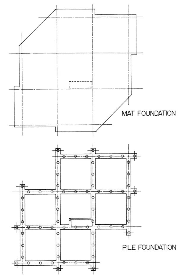
2.2.4 Foundations zolana 2 3 5 9 13 15 18 19 21 21 25 26 30 34 38 41 41
2.3 Building Assembly
2.3.1 Structural Assembly
2.3.2 Typical Connection Details
2.3.3 Non-Structural Elements 2.4 Engineering Properties
2.4.1 Material Properties
2.4.2 Section Properties 2.4.3 Mass of Building
2.4.3.1 Assumptions and Methods
2.4.3.2 Mass Calculation
2.4.3.3 Summary of Mass Calculation
Chapter 3
3.1
3.2
Structural Analysis
The Finite Element Model
3.1.1 Modeling Assumptions
3.1.2 Description of Computer Program
3.1.3 Idealization of the Vivienda Venezolana
Building 3.1.3.1 Elements 3.1.3.2 Structure 3.1.3.3 Mass Distribution Static Analysis 3.2.1 Gravity Load
3.2.2 Top Loads - Lateral and Torsional
3.2.3 The Principal Axis of the Building
3.2.4 Relative Stiffnesses of the Building
PAGE 61 61 64 68 70 71 71 73 75 75 79 83 83 84 85 87 88 90 97 101 101 103 105 107
3.3 Dynamic Properties
3.3.1 Mode Shapes and Periods of Vibration 3.3.2 Comparison with Static Analysis
3.3.3 Comparison with Hand Calculations 3.4 Dynamic Analysis - Earthquake Response
3.4.1 Modal Analysis 3.4.2 Base Response 3.4.2.1 Base Reactions 3.4.2.2 Qualitative Investigation 3.4.2.3 Quantitative Investigation 3.4.3 Story Response 3.4.3.1 Vertical Connections 3.4.3.2 Door Lintels
3.5 Summary of Earthquake Response
3.5.1 Summary of Structural Analysis 3.5.2 Earthquake Response Scenario
Chapter 4 Earthquake Resistant Design Proposals 4.1 Coupling Stiffness
4.1.1 Cross-Sectional Parameter y 4.1.2 Relative Coupling Stiffness a 4.2 Coupling Strength
4.2.1 Softening of the Building 4.2.2 Energy Dissipation
4.3 Design Proposals
4.3.1 Stiffness and Strength Proposals
PAGE 110 111 114 116 118 118 121 121 123 128 131 131 134 139 139 140 143 144 145 145 151 151 152 156 156
4.3.2 Options in Yield Mechanisms 4.3.3 Design Examples 4.3.3.1 Exterior Lintels 4.3.3.2 Interior Lintels Chapter 5 References Appendix A Conclusions
Member Strength Calculations
A.1 Wall Panel Strength
A.2 Vertical Connection Shear Strength
A.3 Lintel Strength
PAGE 159 163 163 165 171 175 179 179 181 183
LIST OF FIGURES
PAGE
1.1 Configurations that Affect Earthquake Resistance 17
of Buildings
1.2 Basic Types and Elements of Precast Panel Systems 20
1.3 Precast Concrete I-Shaped Coupled Wall 22
1.4 Typical Precast Composite Walls 22
1 .5 Classification of Precast Connections 24
1.6 Typical Precast Connection Details 24
1.7 Earthquake Resistant Design Concepts 28
1.8 Comparison of Earthquake Resistant Design Concepts 28
1.9 Relative Coupling Stiffness a 31
1.10 Cross-Sectional Parameter y 31 1.11 Shear Medium Factors K , K , and K 33
3 4~ 5
1.12 Relative Coupling Strength 36
2.1 Vivienda Venezolana 17-Story Apartment Buildings, 42
Caracas, Venezuela
2.2 Closed Section Tube Idealization of Building 43
2.3 Axonometric View of Typical Floor 45
2.4 Open Section Beam Idealization of Building 47
2.5 Plan of Typical Floor 48
2.6 Building Section Through Core 50
2.7 Precasting of Wall Panels 51
2.8 Description of Wall Panels 53
2.9 Wall Panel Details 54
PAGE
2.11 Description of Floor Planks 57
2.12 Floor Plank Details 58
2.13 Partition Layout in Apartments 60
2.14 Typical Foundations 62
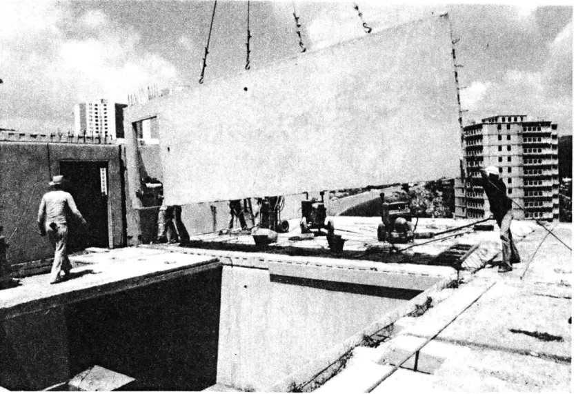
2.15 Assembly of Building 63
2.16 Axonometric View of Building Assembly 65
2.17 Floor Slab Placement 66
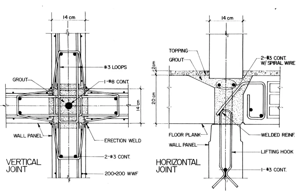
2.18 Typical Joints Between Precast Components 67 2.19 Detail of Door Lintel and Vertical Connection 69
Reinforcement Arrangement at Core
3.1 Structural Analysis Computer Program Organization 86
3.2 Wall Panel Substructures 89
3.3 Floor Slab Substructures 91
3.4 Reinforcement Spring Elements 92
3.5 Assembly of Structure for Typical Story 94
3.6 Global Nodes for Typical Story 95
3.7 Structure Assembly of 17-Story Building 96
3.8 Mass Distribution Key 98
3.9 Summary of Gravity Load Analysis 102
3.10 Summary of Top Load Analyses 104
3.11 Determination of Principal Axes of Building for 106
Static Analysis
3.12 Summary of Dynamic Properties 112
3.13 Comparison of Principal Axes of Deformation 115
3.14 Response Spectrum for the Caracas Region for Buildings 119
on Rock, 1.0g Peak Ground Acceleration, 5% Critical
3.15 3.16 3.17 3.18 3.19 4.1 4.2 Relative Wall
Coupling Strength of Equivalent Coupled
Comparison of Changes in Lintel Stiffness
Comparison of Horizontal an of Lintels
Coupling Beam-Precast Wall Fintel
Exterior Lintel with Diagon
Diagonal Reinforcement
Joint Details Suggested by
al Reinforcement Comparison of Horizontal and Diagonal
in Exterior Lintels
Comparison of Interior Lintel
Reinforcement Design Concepts Comparison of Reinforcement in Interior Lintels
4.13 Evolution of Design
PAGE
125
126
133 Axial Stress Distribution at Base, Earthquake
Direction x, 1.Og
Shear Stress Distribution at Base, Earthquake
Direction x, 1.Og
SRSS Shear Distribution in Selected Vertical
Connections, 1.Og
SRSS Lintel Shear and Moment Distribution, 1.Og
Earthquake Response Scenario
Determination of Cross-Sectional Parameter Y Along Principal Axes of Coupled Building
Comparison of Static Analysis and Fundamental Lateral Modes of Coupled and Uncoupled Buildings Along
Principal Axes
Comparison of Relative Coupling Stiffness Range for Fundamental Lateral Modes of Vibration
Effect of Softening on Response of Fundamental
Modes of Vibration 135 141 146 148 150 153 155 158 160 162 164 164 166 168 169 4.3 4.4 4.5 4.6 4.7 4.8 4.9 4.10 4.11 4.12
13
LIST OF TABLES
PAGE
2.1 Material Properties 72
2.2 Summary of Section Properties 74
2.3 Mass of Materials 76
2.4 Comparison of Mass Calculation of Components 77
2.5 Summary of Mass for Typical Floor 80
2.6 Summary of Mass Calculations 81
3.1 Mass Distribution Assumptions 99
3.2 Summary of Mass Distribution 100
3.3 Top Deflection of Building Along Principal AxesDue 108
to 106 kN Load
3.4 Stiffnesses of Building Derived from Static 108
Analysis
3.5 Comparison of Ratio of Fundamental Periods from 117
Eigenvalue Analysis with Results from Static Analysis
3.6 Comparison of Finite Element Periods with Hand 117
Calculations
3.7 Base Resultants in Response to Earthquake, 1.0g, 122
5% Damping
3.8 SRSS Axial and Shear Stresses at Selected Base 127
Nodes
3.9 Summary of Gravity Load at Base and Compression 127
and Shear Strengths of Selected Wall Panels (ACI Code)
3.10 Comparison of SRSS Axial and Shear Forces on 129
Selected Wall Panels
3.11 Comparison of Design Shear and Moment Strengths 137
of Door Lintels (ACI Code)
3.12 Comparison of Lintel Shearand Moment Response with 137
14
PAGE
4.1 Comparison of Maximum Lintel Shear at 10%g 158
CHAPTER 1 INTRODUCTION
"First, the taking in of scattered particulars
under one idea, so that everyone understands what is being talked about ... Second, the separation
of the idea into parts, by dividing at the joints,
as nature directs, not breaking any limb in half
as a good carver might."
Plato, Phaedrus
Building design is the process by which architects and engineers
seek to solve those problems which they take seriously. These problems may range from a spectrum of formal issues to the structural stability of a building in its environment. However, the optimal solution for one problem may in many cases conflict with those of others, giving rise to building designs that attempt to solve all important problems as best as possible, at least to the level prescribed by building codes. Today,
the number of design issues which must be simultaneously considered
demands a team approach, with architects and engineers that are able
to grapple together with the serious issues in a building's design.
This thesis investigates one such issue and reports on specific solutions
that designers might consider.
Earthquakes are an important consideration in the design process
because of the many locations in the world in which they occur, if only sel-domly; and, therefore they must be considered part of the menu of problems to be solved by designers. The necessity for education of architects in the
seismic design of buildings is demonstrated by the American Institute of Architects' publication of Architects and Earthquakes [ 11. Moreover,
recent work presented by Christopher Arnold on the important effects of *Numbers in brackets refer to sources given in the References.
architectural form and configuration on the response of buildings to earthquakes suggests architects are full participants with engineers in seismic design [ 2 , 3, 4]. Some building configurations that
present problems in earthquake resistance due to non-uniform load
effects or non-uniform resistance are summarized in Figure 1.1.
Under-standing the behavior of these basic configurations should be part of
the architect's collective knowledge of structural systems. In the
words of one architect, "No longer may we specialize in delight and hire consultants to add enough firmness and commodity to get a building
permit" [22].
This thesis is addressed in general to the role of a building's
overall design in responding to an earthquake and in safely resisting
the associated forces induced; specifically these issues are investigated in the context of precast concrete panel buildings, a method of construc-tion that has found extensive use world wide, including seismic regions.
A case study is presented to examine, in detail, issues of earthquake resistant design of these buildings and, in particular, for a precast panel system currently being used in Venezuela. There are several
philo-sophies for the seismic design of precast concrete panel buildings; some are specified or implied by building codes while still others have been proposed by researchers but not yet completely proven or accepted by the
profession. This thesis will demonstrate the feasibilities and problems
associated with one of these proposed design philosophies in this
parti-cular case, and in general for precast panel buildings.
An overview of precast panel buildings is presented in this intro-ductory chapter, including basic configurations and methods of construction
"IRREGULAR STRUCTURES OR FRAMING SYSTEMS"
E
A. BUILDINGS WITH IRREGULAR CONFIGURATION
B. BUILDINGS WITH ABRUPT CHANGES IN LATERAL RESISTANCE
I
C. BUILDINGS WITH ABRUPT CHANGES IN LATERAL STIFFNESS
D. UNUSUAL OR NOVEL STRUCTURAL FEATURES
FIGURE 1.1 Configurations that Affect Earthquake Resistance of Buildings [2]
(SEAOC)
zd
as currently practiced throughout the world. Then, earthquake resistant
design philosophies of these buildings are discussed, both as they are currently implemented in seismic regions as well as those proposed by
researchers as promising. Finally, the scope of this thesis is set forth, based on a case study of the Vivienda Venezolana building in Caracas, Venezuela.
1.1 Precast Panel Buildings: An Overview
The wide spread development of precast buildings was a direct
response to housing needs throughout Europe immediately following
World War II. The process of building in concrete became industrialized with the removal of the casting process from the final location of each member in the structure to a "factory" either on or off site, following which "precast" members are assembled to form the completed building.
Precast concrete elements find many uses in today's construction industry. This thesis will address only precast panel buildings for
which panel type elements constitute the main load carrying members. The basic types of precast buildings are discussed along with the
important elements that contribute to their structural stability.
A particular group of elements, composite or coupled walls, are
investigated further as they are commonly used in this type of construc-tion to efficiently provide for lateral resistance, and thus earthquake
resistance. Finally, connections typically used in panelized construc-tion are reviewed.
1.1.1 Basic Types & Elements
WS Precast concrete panel buildings are constructed of large planar
concrete elements. The basic structural configurations are all
recti-linear and repetitious due to the necessity of reducing the number of
different parts that need separate forms, thus increasing efficiency and decreasing cost. These large prefabricates are assembled into three basic configurations [ 5 , 47]:
1) Cross-wall: The cross wall panel structure
is one in which the bearing walls are
perpen-dicular to the building axis. One-way floor
and roof slabs span between the bearing walls (see Figure 1.2a). Non-bearing wall panels
parallel to the building axis provide lateral load resistance in the longitudinal direction.
2) Long-wall: In long wall, or spine systems, the bearing walls are parallel to the building axis, and again, one way slabs span between bearing
walls (see Figure 1.2b). Non-bearing walls
perpendicular to the building axis provide bracing
in that direction.
3) Two-way system: The third type of large panel
system, the two-way or ring type, consisting of
bearing walls in both directions, carrying two-way slabs (see Figure 1.2c). These slabs must be
bay-sized, unlike the much narrower planks common in one way systems. These systems have a cellular structure that resists lateral loads in both
directions.
A fourth categorization, called a mixed system, is often used, in which
one-way floor systems are supported by cross walls and long walls in
different portions of the structure (see Figure 1.2d).
This later figure also illustrates the important structural elements that are assembled from precast panels: simple walls, composite walls,
and the floor diaphragm. A simple wall is a vertical stack of solid
(a) CROSS-WALL SYSTEM
LOAD BEARING
WALLS
(c) TWO-WAY SYSTEM (d) BASIC ELEMENTS OF PRECAST SYSTEMS
FIGURE 1.2 Basic Types and Elements of Precast Panel Systems
ILtEARNG 4r
,,--MhOA 4'
consists of simple walls coupled together through vertical connections
or lintels (coupling beams). The floor diaphragm is essential for tieing the building together as well as distributing lateral loads to
the wall panels through inplane forces.
1.1.2 The Concept of Coupled Walls.
The composite or coupled wall is an essential element that will reappear again in this thesis. By coupling simple walls that act
independantly, the stiffness of the structural system can be increased. Figure 1.3 illustrates an I-shaped wall that is coupled between the flange and web walls. The large arrows on each flange indicate the couple created by the total shear transferred along the web-flange intersection by the connections.
The increase in stiffness associated with coupling depends on the connector stiffness between the simple walls, the height of the wall, and the configuration of the wall. Several configurations of coupled
walls are illustrated in figure 1.4: Two examples of planar coupled walls, a C-shaped wall, and an I-shaped wall. These elements will be
investigated further in Section 1.2 for their role in earthquake resistant design.
1.1.3 Connections in Precast Panel Buildings
Precast panel buildings were well on their way to wide usage before
their sensitivity to progressive collapse was highlighted by the Ronan Point failure of 1968 [23]. Ronan Point and subsequent examinations
FIGURE 1.3 Precast Concrete I-Shaped Coupled Wall
(C)
FIGURE 1.4 Typical Precast Composite Walls
into abnormal loads and progressive collapse illustrates one of the
fundamental differences between cast-in-place and precast construction:
the necessity of developing the overall structural integrity of the
building by establishing continuity in the connection regions. These same concerns occur in seismic regions, where it is common today to
find panelized buildings ranging from 10 to 20 stories.
Connections in large panel construction serve several basic functions.
Zeck [47], in her report entitled, "Joints in Large Panel Precast Concrete Structures" has surveyed the wide range of connections used to serve
these functions. Figure 1.5 presents a classification system developed
by Zeck for connections based on their type of construction and on their
location in the structure.
Typical connections used in panelized construction are illustrated in Figure 1.6. The cross-sections shown in (a) and (b) are the two most common horizontal connections. The main difference is the use of hollow core prestressed planking and a bearing material in the platform type,
typical of American construction, while the wedge type has a direct vertical transfer of forces through the grout. Plans of typical wet and
dry vertical connections are illustrated in (c) and (d). The wet or
grouted joint provides continuity horizontally through loops extending
from the panels as well as vertically through reinforcement that is
inserted before grouting. The dry vertical connection, more common in
American systems, develop continuity through steel inserts that are
welded or bolted together during assembly. The behavior and design of these connections are discussed more fully in References 5, 8, and 47
Classification of Precast Connections [47]
- -WALL PANEL
(a) HORIZONTAL PL.ATFORM
CONNECTION WALL PANEL (b) HORIZONTAL WEDGE CONNECTION REINFORCING -- GROUT
(c) WET VERTICAL CONNECTION
STEEL PLATES -WELD WA LL iA PAN E REINFORCING
WELDED STUDS
(d) DRY VERTICAL CONNECTION
Typical Precast Connection Details FIGURE 1.5
It is now clear that connections are an important consideration in
the structural integrity of precast panel buildings, and thus are key
to the investigation of their response to earthquakes.
1.2 Earthquake Resistant Design of Precast Panel Buildings.
Vitelmo Bertero identified earthquake resistant design as a problem of
supply and demand [11]. The location and configuration of a building, and the stiffnesses of its members define the probable demands that an earth-quake could make on its lateral resistance system. The designer must
supply the building with an adequate capacity to meet this demand. Disaster might be defined as a very large gap between expectations and performance.
A designer could choose to meet the demand by providing member
strengths that allow them to remain linear elastic. However, this is not generally considered to be economical, resulting in desians that allow some members to behave inelastically, chanqing both supply and demand.
When members yield or fail in a more brittle fashion the buildino softens,
thus increasing or decreasing the demand depending on the building and the earthquake. Furthermore, if members yield in a ductile fashion some demand
is absorbed in the form of eneroy dissipation.
This section investigates several design concepts that involve
inelastic behavior in some of the members, they differ according to
where in the building initial yielding occurs. A promising concept involving coupled shear walls is explored further, where inelastic behavior is initiated in the vertical connections or coupling beams.
1.2.1 Aseismic Design Concepts
In the usual aseismic design procedures for buildings accepted in most seismic codes, member strength is provided on the basis of member
forces derived from a linear elastic analysis. The seismic loads on a
building, however, are not based upon linear elastic behavior, but are
reduced according to the implied ductility of its structural system.
This procedure implies that the sequence of plastification is rather random; thus all potential locations for inelastic action have to be detailed for ductile behavior.
While it is certainly possible to design precast panel buildings with ductile wall panels and strong connections that can develop panel
strength, it may jeopardize the economics of precast panel buildings. Wall panels are often rather brittle elements due to the lack of confine-ment reinforceconfine-ment, and their use in seismic regions must imply higher
design forces than more ductile structural systems. An alternative
aseismic design philosophy that seems particularly well suited to precast panel construction is to purposefully direct the primary inelastic action
into selected structural members. In this concept, favorable primary energy dissipating elements are established along with a favorable
sequence of plastification. Member strength is provided such as to
enforce the chosen sequence of plastification.
This philosophy forms the basis of the New Zealand capacity design philosophy [34]; according to the New Zealand code "energy-dissipating elements or mechanisms are chosen and suitably designed and detailed, and all other structural elements are then provided with sufficient
reserve strength capacity to ensure that the chosen energy-dissipating
Paulay has pioneered the development of reinforced concrete coupled shear
,walls based on this philosophy [36]: the coupling beams act as structural
fuses that yield to protect the gravity load bearing walls. Recently, Fintel has proposed ways of implementing these concepts of Paulay in precast concrete coupled walls [19].
Other researchers have investigated the use of connections between precast panels as a source of inelastic energy dissipation. Pollner has investigated the inelastic cyclic behavior of wet vertical joints in
actual tests [39], while Theil, in a series of computer studies,
demon-strated the beneficial effects on the response of precast composite walls coupled with ductile, dry-type vertical connections [45]. In
similar computer studies and in experiments by Pall, a prototype
"limited slip bolted connection" was developed which relies on friction
to dissipate energy as the connector slips when it reaches yield [32]. In a paper by Becker and Mueller [ 8], three aseismic design
con-cepts for precast panel construction were distinguished, depending
on where the primary inelastic action is directed (see Figure 1.7).
Monolithic Design requires both strong horizontal and vertical connec-tions capable of developing the full capacity of the wall panels; the
other concepts assume the wall panels have low flexural ductility, and direct the inelastic action to the connection regions. Weak Horizontal
Connection Design uses the horizontal connection as a structural fuse that limits earthquake forces by isolating the structure from the ground motion. Finally, Weak Vertical/Strong Horizontal Connection Design uses the vertical connections to dissipate energy and allow for
MONOLITHIC
WEAK HORIZONTAL
CONNECTION
WEAK VERTICAL
CONNECTION
FIGURE 1.7 Earthquake Resistant Design Concepts
DII
UNCONFINED YIELD MECHANISMW
Monolithic
Behavior
null
CONFINED YlELD M EC HAN ISMw
Composite
Behavior
FIGURE 1.8 Comparison of Earthquake Resistant Design Concepts
...... ...... ...... ...... ...... * , , * I I . . I . . . . .... * * * , * * . . . .* . . . .. . . . . . . . . . . . . . .. * , * * " , * . . . . . . . . ...... ...... ...... ...... ... ...... ... ... ...... ***" **** ...... ... ... ......* " * , * * * ...... ....... . ... ... ...... ... ...... ...... ... . . . . ...... * ... ...... ****' ...... ...... [.*.*.,."* -* . , . '.*.*.*.* ... i
...
...
...
...
...
...
...
... ...
...
...
...
...
. ...
...
...
...
...
...
...
...
... ...
...
...
...
...
...
...
--
...
...
...
...
...
...
... .
... ...
...
*"
**
...
...
... ...
...
...
...
... ... ... ... .. ... ... ... ... ... ... ... .... ...A comparison of these aseismic design concepts is illustrated in Figure 1.8 and is based on the development of confined and unconfined
yield mechanisms. In both the monolithic and weak horizontal connection
design concepts, primary inelastic activity occurs in gravity load bearing elements, posing a threat to both the stability and the inte-grity of the building. Moreover, the development of a plastic hinge at the base or slippage of the horizontal connections are unconfined mechanisms, further jeopardizing the structure. Only the weak vertical
connection design concept concentrates inelastic behavior in non-gravity load bearing elements; furthermore, the yielding of vertical connections is confined by the walls as long as the walls have not yet reached their ultimate strength. Other nonlinear behavior of the wall associated with cracking and base uplift would lead to softening but is not seen as a
problem, assuming the building is tied together well. In fact, as noted
by Becker, the most important aspect of aseismic design is tieing the
building together rather than providing ductility in the wall panels or
at the base [10].
Yielding of vertical connections or coupling beams in coupled shear walls offer a softening and energy dissipating mechanism, and does not
threaten the overall stability of a well tied together building. To effectively use coupling elements as primary energy dissipating elements in coupled shear walls, they must become inelastic well before the indivi-dual walls. However, it is not immediately evident what coupling
strength and stiffness relative to that of the wall would lead to the
most favorable energy dissipation characteristics; the proper
The basis for understanding the inelastic behavior of a structure requires a thorough knowledge of the main characteristics and governing
parameters of its elastic response. The shear medium theory provides
such a basis for understanding the response of panelized walls coupled through vertical connections or coupling beams and is reviewed briefly.
1.2.2 Elastic Coupled Response: Shear Medium Theory
The shear medium theory has been widely used in the area of coupled shear walls and shear wall buildings. The coupling problem for the
composite walls shown in Figure 1.4 is basicly governed by only two
parameters a and y. The physical meaning of these parameters is visual-ized in Figure 1.9 and 1.10 [30].
a2 is the relative coupling stiffness. It can be interpreted as the ratio of the relative displacements between the coupled walls and
between the edges of a connection produced by unit forces that act on the top of the walls and on an entire connection at the wall-connection
interfaces (see Figure 1.9). t2 is proportional to
42 ~ k 1 , H2
sm kHwall
where ksm and kwall are the stiffness of shear medium and walls respec-tively, and H is the height of the wall. Thus the height of a building
has a much stronger influence on the degree of coupling than either con-nection or wall stiffness itself.
WALLS
(.WALLS)
SHEAR MEDIUM
H i 1 1
H{~
WALLS SHEAR MEDIUM - WALLS
FIGURE 1.9
Wo
Relative Coupling Stiffness a
Wa: a =0 a= M WES Cross-Sectional Parameter y 2 4w ASM (a) (b) FIGURE 1.10
Y is a cross-sectional parameter that measures the relative
difference in
stiffness and deflection between the uncoupled, but
equally deflecting walls(a = 0, I = combined stiffness of uncoupled
0
walls) and the rigidly coupled walls (c = o, I0 = stiffness assuming
monolithic action), and is visualized in Figure 1.10a. It thus defines the range within which the overall stiffness can be influenced by the
selection of the connection stiffness that is defined by a. This parameter allows a very simple interpretation in terms of forces: y represents the fraction of the total overturning moment that is
resisted by the axial couple for monolithic action (Figure 1.10b). In a paper by Mueller and Becker [29], governing differential equations for a coupled two wall system are presented and solutions
derived in terms of a and Y. Figure 1.11 illustrates several factors that describe the behavior of coupled shear walls for a triangular and, hence, approximate seismic load distribution. K3 defines the shear
flow in the continuous medium, and K is the ratio of coupled and
uncoupled top deflections; these curves are adapted from the work of
Coull and Choudhury [161. K5 represents the square of the ratio of the
periods for coupled and uncoupled action, and was derived by Mueller in a simple and accurate, explicit closed form expression [29].
From Figures 1.11(b) and (c) two distinct regions of coupling
stiffness can be observed: the low a-value range, where the coupling
stiffness strongly affects the response of coupled walls; and the high
a-value range, where the response is practically insensitive to the
coupling stiffness. The shear flow along a connection, (Figure 1.lla), is relatively even in the sensitive range, while it approaches the
16 1 8 24 0 o U.4 0.2 0 ( b)
(
T )2 (C) 0 2 4 6 8 a I. 10 12 14 16Shear Medium Factors K3,K4, and Ks
,,0.6 0 0- .5 -0.4 r* BASE
(a) SHEAR DISTRIBUTION'K'
0.8
RATIO
uneven distribution of a monolithic cantilever beam in the insensitive
range. It is a characteristic feature of coupled walls that for
reasonable low aspect ratios of the coupling beams approximately mono-lithic overall stiffness can be achieved with relatively low coupling
stiffness.
The inelastic characteristics of coupled walls will now be discussed in terms of what stiffness and strength of coupling elements might lead to a good earthquake resistant design based on the weak vertical
con-nection design philosophy presented in Section 1.2.1.
1.2.3 Weak Vertical Connection Design
The advantages of a weak vertical connection design philosophy
were established in Section 1.2.1. With the exception of New Zealand
noted earlier, this type of design is not explicitly encouraged in seismic codes at this time; however, most codes would allow such a design if the effects of inelastic connection behavior are explicitly accounted for in the analysis and design.
If such a design strategy is followed, then the design of coupling elements governs all aspects of the seismic response and is not merely a secondary issue. A weak vertical connection design is conceptually a coupling problem, which can be studied independently of specific wall
configurations or specific coupling devices as shown previously.
Becker and Mueller have proposed four dimensionless parameters that
govern this design [ 8]: a geometric parameter; the relative coupling
stiffness; the ratio of the coupled and uncoupled fundamental periods;
35
respectively as described in Section 1 .2.2; while the later is the
contribution of the axial couple to the ultimate base moment.
The most important parameter governing the effectiveness of the
inelastic deformations along a weak vertical connection is the relative
coupling strength. There has been some discussion in the literature whether high or low relative coupling strength should be used. On the basis of a conceptual single degree of freedom model for elasto-plastic connection behavior [8], it was shown that the relative coupling
strength leading to the best energy dissipation characteristics depends on the stiffness characteristics of the wall configuration. Thus, the following simple rule of thumb was evolved for the relative coupling strength,
(Ty - c)/Mu = 1 - T/T0 [81
where Ty - c denotes the ultimate axial couple, Mu the total ultimate
base moment and T/T0 the ratio of coupled and uncoupled fundamental
periods. This concept is illustrated in Figure 1.12(a) for an I-shaped
wall, although it is general enough to be applied to any of the wall
configurations shown in Figure 1.4 and any coupling elements (coupling beams, vertical connections, etc.)
Results from several computer studies and experiments are sumarized in Figure 1.12(b)
[
8]. It compares the optimum relative coupling strengthleading to the minimum top deflection with the rule of thumb presented above. It should be noted that this optimum strength distribution deviates significantly from the linear elastic force distribution.
1.0 X .8 T .6 uX
F 'y
N I XConnectorsT
MU
MTOTALey
~N
N.
CTT
.2 SDOF- model 0 20 40 60 80 100%Ty-c
T
T-c
/
Mio,
M"u
TOTAL 0 o MITM"
T
oall
Mu
T
Gosh and FintelTOTALO
A Sozen et. al.
(a) (b)
FIGURE 1.12 Relative Coupling Strength [8]
- I
Similarly, the relative coupling stiffness a needs to be selected ic the design of coupled walls. It should be noted that energy dissi-pation effects increase with decreasing T/TO; thus the relative coupling stiffness should be chosen at least at the threshold to the insensitive range, however, increasing the coupling stiffness over this threshold
result in drastic increases of both ductility demand and the number of yield excursions of the connectors [45]. Moreover, from the point of view of serviceability under wind loads, nearly monolithic overall stiffness is desired. It becomes evident that both aseismic and serviceability design considerations suggest a relative coupling
stiffness at the threshold to the insensitive range, approximately
a equal to 4.
This design approach is still the subject of debate among researchers; however, it provides promising earthquake resistant design features for
precast concrete panel buildings which are often percieved as rather brittle structures. Although the theoretical optimum design is based
on simple models of complex buildings, they provide qualitative
indi-cations of stiffness and strength distributions that may provide better earthquake resistance.
This thesis investigates a particular precast panel building, and
suggests possible ways that this theoretical design philosophy might be accommodated in this case, and in general for precast panel buildings.
1.3 A Case Study: The Vivienda Venezolana Building
The previous section has shown that the concept of inelastic
coup-ling action and energy dissipation along weak vertical planes forms the basis of a promising alternative aseismic design concept in precast
panel buildings. In general , this design concept is more effective for tall, long period walls and beam coupling than for low-rise, short
period walls and vertical connection coupling [8]. A 17-story precast
panel apartment building produced in Venezuela by Vivienda Venezolana seemed particularly well suited for a case study based on the former
characteristics, which forms the heart of this thesis. The scope and
outline of the work presented is as follows.
A description of the building system is presented in Chapter 2, both in its overall and detail design aspects. The particular approach
that will be followed is to introduce the building in a more conceptual sense, focusing on a three diniensional respresentation of its spatial and structural organization; next, the separation of the building into its components, so that each is understood, and then assembly procedures
used to construct these buildings are reviewed. Also included are a
summary of the engineering properties essential to the understanding of
the building's static and dynamic behavior.
The structural behavior of the building is investigated in Chapter 3 with a linear elastic analysis. Results are presented for static and
dynamic analyses of a three-dimensional finite element model of the
build-ing, to better understand its response to earthquakes. The nonlinear
behavior of the building in resisting earthquakes is derived from compa-risons of linear elastic force distributions with member strengths
(calculated in Appendix A). These studies imply a scenario of the linear elastic and nonlinear response to an earthquake and leads to a conclusion that the behavior of the door lintels could have considerable influence.
The opportunities presented by the door lintels in this building are investigated further in Chapter 4 in terms of earthquake resistant design proposals, that could in principle be implemented in other precast concrete panel buildings. The design of coupling beam stiffness, strength and
details are based on concepts of aseismic design presented above; and several design examples of precast concrete panels and assembly procedures are proposed that could actually be used to implement these concepts.
Conclusions, in Chapter 5, recommend further investigation of the
use of coupling beams in precast panel buildings as a means to provide energy dissipating and softening mechanisms. The optimism that is present
in analytical and experimental investigations by researchers of this
concept, the practical success of coupled shear walls in cast-in-place construction, and the continued need for economical but structurally reliable methods of building provide strong incentives to pursue this to the fullest extent. Integrating these concepts into the design of
buildings demands a team approach, with both architects and engineers aware of the opportunities present in these concepts of earthquake resistant design.
CHAPTER 2 BUILDING DESCRIPTION
This chapter contains a descriotion of the Vivienda Venezolana
building. Its overall form and organization is first established so that the description of the elements and details are placed in context. The
logical extension of this discussion is the assembly of the parts into
the building. Finally, engineering properties of the building are
summarized along with the methods they were obtained.
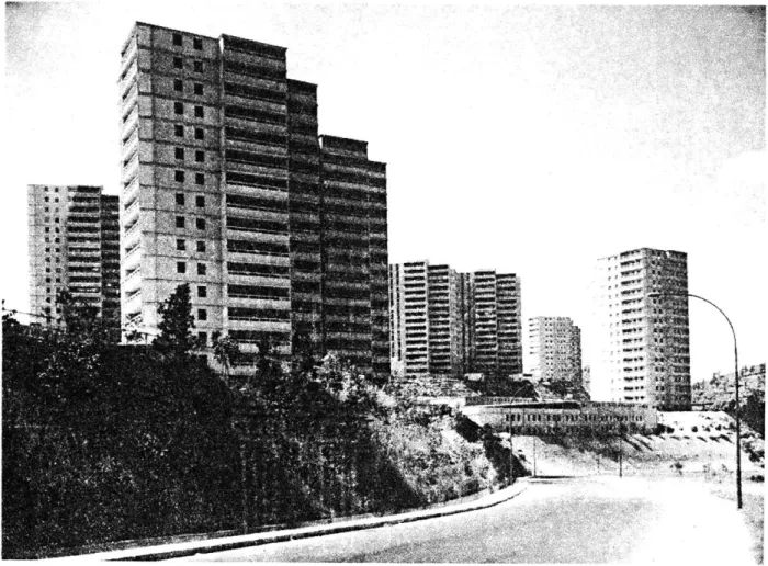
2.1 An Introduction to the Vivienda Venezolana 17-Story Building. Vivienda Venezolana S.A., a company in Caracas, Venezuela, has
designed, and currently produces and markets the building that is the
focus of this investigation: A 17-story precast panel apartment building (see Figure 2.1). This apartment building was developed in response to a need in Venezuela for low-cost housing, and employs industrialized
housing methods that have proven successful in reducing housing costs
elsewhere in the world. In addition to economically providing for the
functional and spatial needs of the occupants of these housing units, this system must also withstand earthquakes that occur in the Caracas
area. The description of the system designed to meet all of these
requirements is the focus of this chapter; and the system's earthquake resistance is the focus of this thesis.
The structural organization of the building consists of precast
concrete wall panels and floor planks. The wall panels form a cellular structure based on an 8 meter square tube (see Figure 2.2a). This dimension is a good module for apartments and for spanning with floor
FIGURE 2.1 Vivienda Venezolana 17-Story Apartment Buildings,
(b)
FIGURE 2.2(d)
(c)
Closed Section Tube Idealization of Building
planks. Three of these apartment cores share common walls to form a
larger, L-shaped tube (see Figure 2.2b). Two of the L-shaped tubes
are connected to define the vertical circulation core at the center of the building (see Figure 2.2c). The resulting form of the building allows each apartment two exterior walls for light and ventilation; a balcony is attached to one of these walls, supported by smaller wall
panels. This results in an overall building configuration that is depicted in Figure 2.2d.
The structural system idealized in Figure 2.2 results in a
struc-tural form that has inherently good earthquake resistance: a series of closed tubes. This basic form, sometimes called an "egg crate", has
been used successfully in other seismic regions of the world such as in
Russia and Yugoslavia. The closed tubes give the building a high torsional stiffness relative to other, more open systems, and results
in a stable seismic resistant building form.
Atypical floor of the structural system is shown in Figure 2.3. This figure illustrates how the apartments, defined by the wall panels, are organized in a "pin-wheel" pattern around the vertical circulation
core. Entrances to the apartments from the core are concentrated at the center of the L-shaped tubes. This results in a concentration of openings in the walls that form a region of increased flexibility in the
struc-tural tube. The tube is pierced similarly at the balcony doorways
along the exterior of the building. Window openings are not as influ-ential due to the rather deep lintels that remain. The existence of
l,
tube idealization as a model of the building's lateral resistance system;
rather, it might be thought of as an upper bound idealization where the entire building behaves monolithically as a uniform beam.
In contrast, a lower bound idealization is illustrated in Figure 2.4 that neglects the door lintels. The resulting structural form is a
series of open section composite walls that bend independently, although connected by a floor diaphragm that couples their lateral and torsional
deformations. This idealization is more flexible in lateral and torsional
resistance than the actual building, where door lintels couple the open section composite walls three-dimensionally in a way similar to the coupled shear walls described in Chapter 1.
The point-symmetry of the building about its center is illustrated clearly in Figure 2.4: every element is balanced by a corresponding element related by a 1800 rotation about the center point of the
build-ing. There are three distinctly different composite walls in this
idealization, each has its point-symmetric counterpart. This results in
a total of 6 individual walls providing the lateral load resistance for the building, as well as enclosing the apartment and core spaces.
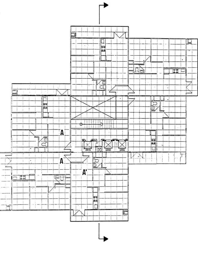
A plan of a typical floor, Figure 2.5, illustrates the organization
of space in the apartments and core within the structural framework
defined by the wall panels and floor planks. There are two different apartment types: Type A has an entrance directly into the apartment
from an opening in the wall panel, while Type A' has slightly less
floor area because it provides a small entrance alcove for two apartments.
All apartments are organized with living space arranged between the
-1-WALL TYPE A
-F
WALL TYPE B
WALL TYPE C
COMPLETE BUILDING
48
K
-- 4-I -~ I ---r
_-~
--
j--17 1F
1~~.
T
- 1*Fi7i~
KKI
T
IThTITh'P
I
m r
, 11I7 I 2 -
: 1 1 1 1 1 1 1 !
_____________________________ - ______ ~ = - = I = ILI lii -liii~ii~
--hr I ~ III iIII~JFII'II I I ____ I ~ I~r
r
7A
AFp
____________ r~ ___.7
7
17
--- -----rKnmvFi7I
I I I -l iiTh7T1771
I i~j If~
FIGURE 2.5 Plan of Typical Floor
L11 I~ V
!
iI I
.1
I
...
balcony. The bedrooms and bathroom are located in the remainder of the apartment; the bedrooms have exterior exposures. All apartments
have three bedrooms and one bathroom.
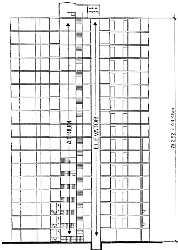
The building section in Figure 2.6 illustrates that the core is
open vertically the height of the building; this allows light and air
to enter from the top of the core at the penthouse. The core contains three elevators, a trash chute, and one stairway; and the penthouse
contains the elevator's mechanical systems.
The next section will deal more specificly with the parts that make up the building: the wall panels, floor planks, partitions, topping and fill, penthouse, and foundation.
2.2 Components of the Building.
The Vivienda Venezolana system is an assemblage of parts, some
produced in the factory and others are added on site during construction. The two major types of parts produced in the factory are precast concrete
wall panels and floor planks. Elements that are assembled at the site
include the foundation, joints, topping, and partitions. This section
describes the production, materials and details of these components.
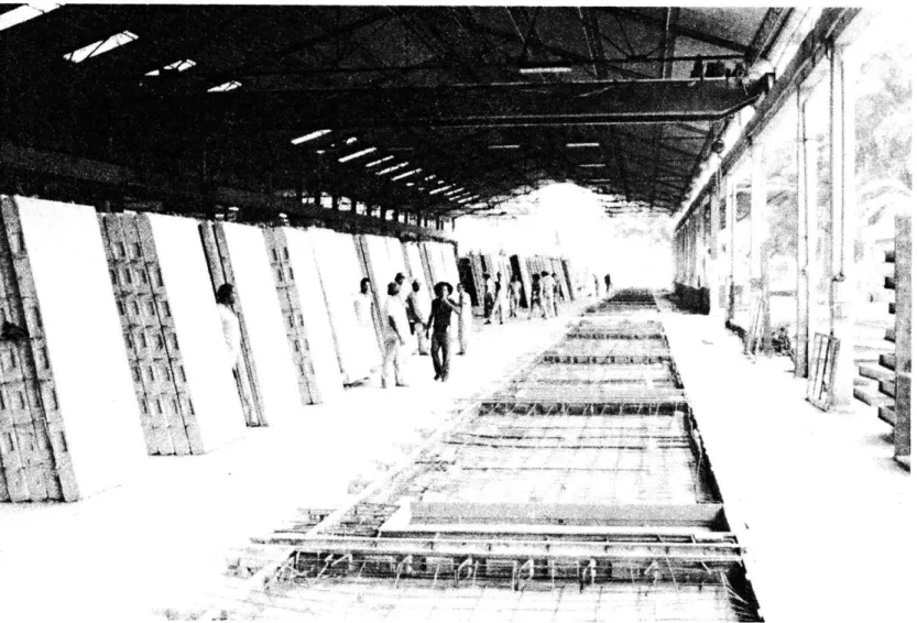
2.2.1 Precast Wall Panels.
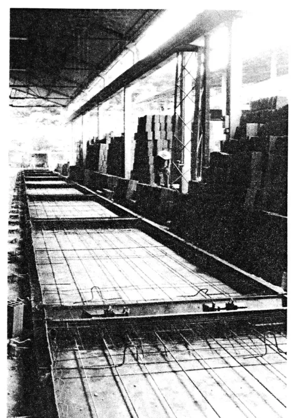
The precast wall panels are produced in a factory using industrialized production systems. Concrete is poured into horizontal, flatbed forms that have been prepared with the proper reinforcing steel arrangement and required door and window openings (see Figure 2.7). The fresh wall panels are removed from the forms and stored outside, vertically in the
"IVA
factory storage area for curing. Due to the hot and humid climate, the
panels cure quickly without the use of steam curing or other more
compli-cated methods to increase productivity.
All wall panels produced are 2.40 meters in height, 0.14 meters thick,
and with the exception of the balcony wall panel, all panels are 7.72 meters long. In addition to the wall panels, a precast balcony rail is produced that is installed as a single unit on site. The typical wall panels produced for the 17-story building are illustrated in Figure 2.8 and includes a key denoting the wall panel's location in the building. The reinforcement of the wall panels is of particular importance to the behavior of the building; and this is most evident at regions of the panel that have a reduced concrete section due to door and window
openings. Typical reinforcement of wall panels is illustrated in Figure 2.9a. All wall panels are reinforced with two layers of
200 mm x 200 mm welded wire fabric that provide a horizontal reinforce-ment ratio of 0.0007 and a vertical reinforcereinforce-ment ratio of 0.0014.
Edge reinforcement of 2 - #3 bars is provided around the perimeter of the
panel as well as vertically along door openings. This reinforcement
typically increases the wall reinforcement ratio to 0.0015 horizontally and 0.0017 vertically. Window openings are reinforced with 3 - #3 bars
along the sides and 3 - #4 bars top and bottom. Erection angles and #3
loops positioned along the vertical edges are for connections to adja-cent panels during building assembly.
A typical section through a door lintel is presented in Figure 2.9b.
PANEL TYPE
B-IELEVATION
1-1.60 TYF? E 0DESCRIPTION
BALCONY END WALL
0 0 0.30 .O-96 E 100. TY P
101
1.20Li
FACADE PANEL-2 WINDOWS
FACADE PANEL-.6m LINTEL
INTERIOR PANEL-0.9m LINTEL
INTERIOR PANEL- 1.2m LINTEL
INTERIOR PANEL- SOLID
BALCONY RAIL
772m TYP.
WALL PANEL LOCATION KEY PLAN
Description of Wall Panels F- I F-2 I -I 1-2 T-I BALC. I FIGURE 2.8
ERECTION ANGLES (TYP)
a) TYPICAL WALL PANEL REINFORCEMENT (PANEL F-2)
STIRRUP SPACING PANEL LINTEL ~TYPE ISPAN___ F-2 1.6m 200mm I-2 1.2m 140mm - I 0.9m 140mm
b) TYPICAL SECTION THRU DOOR LINTEL
Wall Panel Detailsdoorway carrying the top steel for the next lowest floor's door lintel. All door lintels are reinforced with 2 - #7 bars top and bottom for bending resistance. Shear reinforcement is provided by #3 stirrups that are bent over the top steel during erection before grouting the beam.
2.2.2 Precast Floor Planks.
Precast prestressed floor planks are produced in flatbed forms that enable the pretensioning of all planks (see Figure 2.10). In this
pro-cedure the casting materials are transported to the forms. In a more
sophisticated method employed at the same factory, the floor planks are
individually prestressed and cast on portable carts allowing the forms to be transported to the materials.
Most floor planks span 7.86 meters from center to center of suppor-ting wall panels and span in only one direction. The typical floor
planks produced for the 17-story building are illustrated in Figure 2.11,
and their locations in the building are indicated. The most common floor plank is 2.57 meters wide and three planks are needed to span one apart-ment. Balcony planks are 1.6 meters wide. The core uses one 1.6 meter
panel, a precast stair plank, and several smaller planks.
Hollow clay tiles or cement blocks are used in floor planks to reduce
their weight. An individual unit is 20 cm x 30 cm x 16 cm and weighs
about 7 kg; this results in a density of 730 kg/m3 and a 70% reduction in weight as compared with the concrete.
Typical floor plank details are illustrated in Figure 2.12. The
FLOOR PLANK
L-A L-BPLAN
E 3.28m L-1.60 L-2.57DESCRIPTION
CORE FLOOR PLANK
CORE FLOOR PLANK
BALCONY FLOOR PLANK
APARTMENT FLOOR PLANK
STAIR PLANK
I-1-o0
FLOOR PLANK
LOCATION KEY PLAN
Description of Floor Planks
STAIR
7.72m TYR
2.57m
L-2.57
PRESTRESSING CABLE
\-CLAY TILE OR CONCRETE BLOCK
1.60
m10
L-..6m
L-I.60
a) TYPICAL CROSS-SECTION THRU FLOOR PLANKS
L-2.57
K
L-1.60
TYPICAL SECTIONTHRU CORBEL
b) TYPICAL PLAN VIEWS OF PLANK BEARING EDGES
Floor Plank Details
w
length of the plank in the direction of its span. As explained above,
%the clay tiles have the effect of reducing the weight and increasing the
efficiency of the planks; however, they also have the effect of reducing the inplane stiffness of the floor diaphragm it forms between the wall
panels in the building. The actual depth of the floor plank (including topping) of 22 cm is reduced to an effective depth of approximately 7 cm,
thus reducing the amount of material present to resist inplane floor
diaphragm forces. Regular reinforcement is used to provide temperature
and shrinkage reinforcement and to provide continuity to adjacent floor planks with rebar inserts that are field welded. The floor planks are
cast with two corbels on each bearing edge that transfer the floor load onto the wall panels at points rather than continuously (see Figure 2.12b).
2.2.3 Partitions, Topping, and Fill.
The partitions, and floor plank topping and fill complete the
apartment and core interior spaces defined by the wall panels. These
components are constructed by on-site labor after the structural frame-work of wall panels and floor planks has been erected. A typical
apart-ment layout is illustrated in Figure 2.13. The partitions are
con-structed of hollow clay tile blocks wiithi a 15-20 mm layer of mortar on each face as a finish. The two thicknesses of partitions correspond to 10 cm and 15 cm clay tile blocks respectively.
A 20 mm topping covers the precast planks for leveling. The fill
areas on the plan are for bathroom areas that require drainage pipes
366O
![FIGURE 1.1 Configurations that Affect Earthquake Resistance of Buildings [2]](https://thumb-eu.123doks.com/thumbv2/123doknet/14755538.582323/17.918.114.822.159.955/figure-configurations-affect-earthquake-resistance-buildings.webp)
![FIGURE 1.12 Relative Coupling Strength [8]](https://thumb-eu.123doks.com/thumbv2/123doknet/14755538.582323/36.1188.131.1100.100.789/figure-relative-coupling-strength.webp)