A Controllable, Nano-Volumetric,
Transdermal Drug Delivery Device
by
Aimee B. Angel B.S. Mechanical Engineering
Massachusetts Institute of Technology, 2000
Submitted to the Department of Mechanical Engineering in Partial Fulfillment of the Requirements for the Degree of
Master of Science in Mechanical Engineering at the
Massachusetts Institute of Technology June 2002
MASSACHUSETTS INSTITUTE
OF TECHNOLOGY
OCT25 2002
LIBRARIES
C 2002 Massachusetts Institute of Technology. All rights reserved.
Signature of Author:...
Certified by:...
Department of Mechanical Engineering May 24, 2002 ... ... ... ...--- ..--
---Ian W. Hunter Professor of Mechanical Engineering and Professor of BioEngineering Thesis Supervisor A ccepted by:...
---Ain A. Sonin Professor of Mechanical Engineering Chairman, Department Committee on Graduate Students
A Controllable, Nano-Volumetric,
Transdermal Drug Delivery Device
by
Aimee B. Angel
Submitted to the Department of Mechanical Engineering on May 24, 2002 in Partial Fulfillment of the Requirements for
the Degree of Master of Science in Mechanical Engineering
ABSTRACT
A significant number of recently developed drugs are based on naturally occurring
compounds, such as proteins, peptides, and carbohydrates. Often, these pharmaceuticals, generally referred to as biologicals or macromolecules, cannot be delivered by traditional methods of drug delivery. In many cases, the precise volume of delivery, location of delivery, and delivery profile are important factors in the effectiveness of the therapeutic. Adequate, widespread mechanisms for delivery of biologicals do not currently exist, and the ultimate utility of these new pharmaceuticals depends on the creation of new processes and devices to deliver the drugs.
This thesis gives a detailed overview of a novel microneedle drug delivery device that is designed to deliver small volumes of biologicals to a known depth below the stratum corneum. The stainless steel microneedles are in the range of 100 - 175 Itm OD and 25 - 100 pim ID, and
minimize the pain often associated with delivery by injection. The device is controlled by a microprocessor that inputs any desired current profile to an electrochemical actuator, which controls the delivery of 100 /iL to 1 mL of liquid drug. A model to predict the delivery profile of the device based on the charge input to the electrochemical actuator was created and verified experimentally. The volume flow out of the device falls within the expected upper and lower bounds, as set by the tolerances of the microneedle tubing. The tests show that 80 - 90% of the drug is delivered in each run, and that peak flow rates of approximately 1 tiL/s can be attained. Two functional prototypes integrating the subsystems of the device were created to demonstrate the design concepts.
Thesis Supervisor: Ian W. Hunter
TABLE OF CONTENTS
1 INTRODUCTION ... ----.... ---... 8
2 BACKGROUND...---... 9
2.1 ROUTES FOR DELIVERING THERAPEUTIC COMPOUNDS TO THE BODY...9
2.1.1 O rally adm inistered drugs...9
2.1.2 Passive transderm al delivery...10
2.1.3 M ucosal surface delivery... ... ... --11
2.1.4 P ulm onary delivery ... ... 11
2.1.5 D rug delivery by injection ... 12
2.1.6 Optimal route for drug delivery of biologicals ... 12
2.2 EXISTING DEVICES FOR DELIVERING BIOLOGICALS ... 13
2.2.1 lan's MEDIPAD@ drug delivery system ... 13
2.2.2 Alza's E-Trans@ electrotransport drug delivery technology... 15
2.2.3 Alza's MacrofluxTM skin interface technology... 16
2.2.4 Abbott's AIM~plus drug delivery technology ... 17
2.2.5 Bio Valve's drug delivery technology...18
2.2.6 M ulti-Test II... ... 21
2.3 OTHER MICRO-TECHNOLOGIES USED TO DELIVER DRUG ACROSS THE SKIN ... 22
2.3.1 Silicon Microhypodermic Needles for Injection (Lin et al) ... 22
2.3.2 Microhypodermic polysilicon needles (Talbot and Pisano) ... 23
2.3.3 Metallic microhypodermic needles (Brazzle et al) ... 24
2.3.4 Metal needle with multiple output ports ... 25
2.3.5 Microprobes for DNA injection (Hashmi et al) ... 26
2.3.6 Glass Microcapillaries (Chun et al)... 27
2.3.7 Microfabricated Neural Probes (Chen and Wise)... 28
2.4 FLUID DELIVERY IN NATURE: THE MOSQUITO ... 29
2.4.1 M osquito m outhparts ... ... ----... 29
2.4.2 Sucking blood ... ... ... --. -... 30
2.4.3 Vibration of the fascicle... 31
2.4.4 Lessons learned from insect injections ... 31
2.5 ANATOMY AND PHYSIOLOGY OF HUMAN SKIN ... 32
2.5.1 Structure of hum an skin...32
2.5.2 The ep iderm is ... ... --... 32
2.5.3 D rug delivery dep th ... .. ... 34
3 LIMPET CONCEPT ...---... 35
3.1 DESIGN CONCEPT ... ---... 35
3.2 PRODUCT SPECIFICATIONS ... ---... 35
3.3 FLOW OF USE OF THE LIMPET ... ---... 36
4 LIMPET COMPONENTS...---... ... ---... 37
4.1 INTERFACE BETWEEN THE DRUG AND THE HUMAN... 37
4.1.1 Pyram ids... ... ... --... . . ... 3 7 4.1.1.1 LPK F Prototyping M achine ... ... ---... 37
4.1.1.2 H AA S M achining Center ... --... ... 38
4.1.1.3 Overview of Machining Technique... 39
4.1.1.4 PM M A Arrays...---... ... .. --- --... 40
4.1.1.5 Polycarbonate Arrays ... ... -... ---... 42
4.1.1.6 Plastic needles arrays - skin penetration ... 43
4.1.1.7 A lum inum A rrays... ... ... .--.... ... 43
4.1.2 Stainless steel needles...46
4.1.2.1 H ypoderm ic needles...--... . ---... 46
4.1.2.2 Stainless steel tubing availability, pricing ... ... .... ... 47
4.1.2.3 G rinding tips on the needles... 48
4.1.3 Preferred drug to human interface... 49
4.2 N EEDLE INSERTION INTO THE SKIN...50
4.2.1 W ill commercially available needles to the job? ... 50
4.2.2 Force of needle insertion... 50
4.2.3 Needle failure ... 53
4.2.3.1 Failure due to buckling...53
4.2.3.2 Failure due to fracture ... 53
4.2.4 Peak flow rate required ... 53
4.2.5 Peak pressures sustained by tubing... 54
4.2.6 Perpendicular versus parallel insertion ... 54
4.2.7 Rotation into the skin... 56
4.2.8 Suction to draw skin into Limpet ... 56
4.2.9 Preferred needle insertion technique... 57
4.3 LIM PET ATTACHMENT TO THE SKIN ... 58
4.3.1 Attachm ent via adhesive ... 58
4.3.2 Attachment via vacuum suction ... 59
4.3.3 Attachment via m echanical coupling... 59
4.3.4 Preferred attachm ent...59
4.4 D ELIVERY ACTUATION ...--- ...-60
4.4.1 Electrochem ical decomposition of water... 60
4.4.1.1 The chemistry of electrolysis using sulfuric acid ... 60
4.4.1.2 Electrolysis as an actuator for the Limpet ... 61
4.4.2 Vaporization of Water ... 61
4.4.2.1 Heater calculations...61
4.4.2.2 Testing the theory...62
4.4.2.3 Vaporization as actuator for the Limpet... 62
4.4.3 Chem ical Actuation ... 63
4.4.4 Preferred actuation technique...63
4.5 N EEDLE/D RUG CHAMBER COMMUNICATION ... 64
4.5.1 Needles as a part of the drug vial... 64
4.5.2 Needles enter the drug vial just before delivery ... 64
4.5.3 Preferred needle/drug interface ... 64
4.6 ELECTRONICS... ... ---... 65
4.6.1 Texas Instruments M SP430F149IPM ... 65
4.6.2 Texas Instrum ents M SP430FJJOIPW ... 65
4.6.3 Completed circuits...66
4.7 IMPEDANCE TESTING ... ... ---... 67
4.8 POW ER ... . ---... 69
4.9 LIM PET DESIGN CONCEPTS AND PROTOTYPES...71
4.9.1 D esign concepts... 71
4.9.1.1 Bent needles: Translation of drug vial onto needle tips, rotation into skin... 71
4.9.1.2 Needles in a plane: Rotation to join vial and needles, rotation into skin ... 72
4.9.2 Limpet prototypes ... 73
4.9.2.1 Rotation mock-up...73
4.9.2.2 Rotation prototype to scale...74
4.9.2.3 Functioning prototypes...75
4.10 APPLICATOR...---... 76
4.10.1 Prototype speci fications... 76
4.10.1.1 M icro-stepper motor...76 4.10.1.2 Spur Gear ... ... ... .... .77 4.10.1.3 Gear assembly ... 78 4.10.1.4 Applicator circuit ...---..--- 79 4.10.2 Completed prototype... ... . 79 5 PUM P TESTS ... ... ... ----.. ... 81 5.1 PUMP CONFIGURATION... -... 81
5.1.2 Pump components... 82 5.1.2.1 Drug Vial ... 82 5.1.2.2 Drug ... 83 5.1.2.3 Pump Top...83 5.1.2.4 Electrodes...83 5.1.2.5 Electrolyte ... 84 5.1.2.6 Flexible M embrane ... 85
5.2 PUMP TESTING PROCEDURE, EXPERIMENTAL APPARATUS ... 85
5.3 THEORETICAL FLOW PREDICTIONS ... 90
5.3.1 Pressures that m ust be overcome to create flow... 90
5.3.1.1 Surface tension in the needle...90
5.3.1.2 Pressure required to fully deflect the flexible membrane ... 90
5.3.1.3 The influence of delivering to skin...91
5.3.2 Electrolytic decomposition of water ... 91
5.3.2.1 Gas production based on charge input... 91
5.3.2.2 Electrolyte used in gas production based on charge input... 91
5.3.3 Equations that effect the flow ... 92
5.3.3.1 Ideal gas law...92
5.3.3.2 Hagen-Poiseulle equation for flow though a cylinder ... 92
5.3.4 Unified model predicting flow characteristics... 93
5.3.4.1 Differential equation that describes volume flow based on current input... 93
5.3.4.2 Assumptions...93
5.3.4.3 Establishing the initial conditions ... 94
5.3.4.4 Equations that determine pump pressure and volume flow ... 94
5.3.5 Further work...97
5.3.5.1 Prediction of steady state flow rate ... 97
5.3.5.2 Calculation of required current input based on desired output ... 97
5.4 RESULTS ... 98
5.4.1 Current versus voltage graph for different electrode configurations ... 98
5.4.2 Experimental results offlow tests ... 100
5.4.2.1 Pump 8 ... 100
5.4.2.2 Pump 31 ... 104
5.4.3 D elivery into pig skin: Pump 34 ... 108
5.5 D ISCUSSION ... 112
5.5.1 Limitations of model based on tolerances of manufacturing technique ... 112
5.5.2 Steady state delivery ... 112
5.5.3 Reducing the tim e required to being delivering drugs to the skin ... 112
5.5.4 Reduced flow rate while pushing out the final volume of drug...113
5.5.5 Percentage of drug delivery ... 113
5.5.6 Increased dynam ic viscosity of the drug...114
5.5.7 D if iculty sealing the pumps ... 114
5.6 SUM MARY AND CONCLUSION OF THE PUMP TESTING... 115
6 CO NCLU SIO N ... 116
6.1 FUTURE W ORK... 116
6.1.1 Quantified delivery into pig skin...116
6.1.2 Further investigation of technical issues and optim ization of design...117
6.1.3 Collaboration with pharmaceutical companies...117
6.1.4 D evelopment offully working prototype, design ... 117
6.1.5 Clinical trials, production, etc...118
BIBLIO G R APH Y ... 119
CRED ITS...122
APPENDIX A: G-CODE FOR MACHINING PYRAMIDS ON THE HAAS...123
APPENDIX B: NEEDLE FAILURE CALCULATIONS (USING MATHCAD)...135
APPENDIX D: MEMBRANE DEFLECTION (USING MATHCAD)...141 APPENDIX E: FLOW CALCULATIONS (USING MATHCAD)...143 APPENDIX F: VISUAL BASIC CODE TO TAKE IN DATA FROM MICRO-BALANCE AND AGILENT 34970A DATA ACQUISITION SYSTEM ... 151 APPENDIX G: PROTOCOL FOR RADIOACTIVE TESTING ... 160
ACKNOWLEDGEMENTS
This thesis never would have been possible without the help of people at the BioInstrumentation Lab at MIT and our sponsors, Norwood Abbey, Ltd. in Australia.
Specifically, I would like to thank Professor Ian Hunter for his interest, assistance, and support throughout the project. Peter Hansen, President and CEO of Norwood Abbey, and Peter Simpson, Chairman of Norwood Abbey, in addition to contributing the initial interest and ongoing funding, also showed tremendous commitment to the project and offered useful insight, motivation, and contacts that influenced the evolution of the design. Dr. Cathy Hogan and Bryan Crane regularly contributed considerable time and effort beyond their own projects to assist with the biology and design work for the project. Johann Burgert and Jan Maligek were absolutely essential to getting any and all of the electronic components of the project to work. Dr. John Madden, James Tangorra, and Patrick Anquetil all offered helpful criticism and guidance. Thanks to Wilson Chan for working on the needle insertion apparatus and applicator module, and Laura Proctor for working on the impedance circuit. Thanks to the women of the Newman Lab, especially Rachel Peters, who provided a constant source of amusement, support, bathroom breaks, and perspective on our research projects. Finally, a world of thanks to Peter Madden, whose friendship and technical assistance were essential to the project. "Machining on the Mazak," tea breaks on Killian Court, hours of talks (some about research.. .most not), and late-night walks home were the things that got me through my Master's.
1
Introduction
Historically, drugs were simple, fast-acting chemical compounds that were delivered to the body by hypodermic needle injection or orally administered as pills and liquids. Over the past three decades, significantly more complex formulations have been developed that are based on naturally occurring compounds, such as proteins, peptides, and carbohydrates, generally referred to as biologicals or macromolecules.
The development of these new pharmaceuticals brings with it new considerations of the optimal method for delivery. Many of the new drugs are unstable and have short half-lives, and are therefore only effective if they are delivered locally to the target tissue. Many biologicals, such as anti-cancer compounds, are extremely toxic, so it is desirable to deliver them locally in order to reduce the severity of the side effects that usually occur with systemic administration. In many cases, the precise volume of delivery, location of delivery, and profile of delivery are important factors in the effectiveness of the therapeutic. Adequate, widespread mechanisms for delivery do not currently exist, and the ultimate usefulness of these new pharmaceuticals depends on the creation of new processes and devices to deliver the drugs.
As there is no widespread solution to the problem of delivering biologicals, there is both a large need and a strong opportunity for creating a device that is able to fulfill the specific needs of delivering biological compounds. This is especially true for use in home-based delivery systems, where there are few acceptable solutions.
Norwood Abbey, Ltd., a drug delivery company based in Australia, funded this project with the goal of developing a micro-needle device that would be able to deliver small quantities of high-molecular weight biologicals over a programmable delivery profile to a specific location in the skin. Their main requirements for developing a device that optimally delivers biologicals to humans and has the potential for widespread acceptance were:
* Controlled delivery o Quantity of drug
o Delivery profile of drug * Site-specific delivery
o Location on body
o Depth of delivery below the skin
" Inexpensive
* Suitable patent position to protect device
This thesis details the overall product concept for new controllable drug delivery device, known as the LimpetTM. The project is highly collaborative, with many people working on several components of the Limpet. The author has attempted, in the sections that follow, to describe the motivation for the project, the overall concept of the drug delivery system, the individual components of the Limpet, the key results to date, and further work to be completed. References to other theses where additional information about the Limpet is published, are indicated where appropriate.
2 Background
In order to determine the best solution the problem of delivering biologicals to humans, it is first necessary to understand the different routes for drug delivery into the body, the existing drug delivery technologies that may compete with this design, how small volumes of fluid are delivered in nature, and the anatomy of the skin. Next follow sections that deal with each of these issues.
2.1
Routes for delivering therapeutic compounds to the body
Five general routes exist for delivering therapeutic compounds to the body. The choice of delivery route is dependent on several technical and non-technical considerations such as the chemical nature of the pharmaceutical, where in the body the drug is to act, the optimal drug delivery profile, whether the therapy is administered by medical staff or the patient, and the patient's preference for delivery. The five routes: oral, transdermal, mucosal, pulmonary, and injection are described in more detail below with a discussion of their applicability to delivering protein, peptide, and carbohydrate-based pharmaceuticals in a controlled manner.
2.1.1 Orally administered drugs
There is a long and established history of delivering drugs to the body by means of oral ingestion. Pills and liquid medications are simple, painless ways to deliver a known dose of a pharmaceutical, and oral administration is the most convenient and economical method of delivering drugs to the body. Oral administration, however, is not very effective for delivering biologicals because of the chemical composition of the drug, the dosage profile inherent in orally administered drugs, and the location of drug delivery.
Biologicals are based on naturally occurring compounds, such as proteins, peptides, and carbohydrates, which are readily broken down in the gastro-intestinal system. Therefore, the potency, and corresponding therapeutic effectiveness of many biologicals, is reduced because of the partial degradation that occurs before they reach their desired target in the body.
Although there have been significant improvements in the design of pills for controlled release, orally administered pharmaceuticals generally result in non-constant drug levels in the body which causes ineffective therapy. Figure 2.1 shows the expected drug levels in the body using traditional and controlled dosing.
Maximum desifed "I
Minimum effective mi
Dos& Dosb Dos. Time ---.
(b)
Maximum dmAied mie
Minimum efflctivo lw&*l Da*e
Tim &
Figure 2.1: Graphs showing drug levels in the blood with (a) traditional drug dosing and (b) controlled-delivery dosing. (Taken from Brannon-Peppas, 1997)
Furthermore, orally administered drugs generally consist of pre-determined doses that deliver treatment continuously after ingestion. For many biologicals, it is desirable to have a controllable delivery mechanism that can be varied in delivery profile and total delivery volume, based on each specific case.
Finally, oral administration of drugs creates systemic, rather than local delivery. As mentioned above, many new biologicals are particularly toxic, and have many negative side effects. These side effects can be reduced significantly if the drugs are only delivered to the specific locations where they are required. This will also reduce the amount of pharmaceutical required overall and allow for more effective delivery.
2.1.2 Passive transdermal delivery
While the skin is an excellent barrier to most environmental influences, it is not entirely impervious. Passive transdermal drug delivery uses the ability of some molecules to permeate across the stratum corneum in order to achieve local or systemic therapeutic effects.
Transdermal delivery consists of drugs that are topically administered, usually in the form of creams, gels, or patches.
Transdermal delivery allows drugs to enter the body while avoiding the problems listed under the oral delivery method, such as gastrointestinal absorption and drug deactivation by
digestive tract and liver enzymes. While these are very positive benefits to patients, transdermal delivery also has several limitations when it comes to delivering biologicals.
As mentioned above, it is highly desirable to be able to control the drug delivery profile of biologicals so that patients get the most effective therapy. Since the rate of delivery in the passive transdermal approach is controlled either by the permeation rate across the skin (which is itself variable, depending on many factors), or by a physical barrier in the patch, the rate cannot be actively controlled for each situation. Furthermore, it can be extremely important in the delivery of biologicals to know the exact amount of drug delivered, and not to waste much drug during delivery. This can neither be monitored, nor guaranteed in transdermal delivery. In fact, in many patch-based systems, for every dose of drug administered, 400 to 500% of that dose is
also wasted in the patch.
Finally, the high relative molecular mass of many biologicals also limits the usefulness of transdermal delivery. Only small molecules are able to permeate the stratum corneum, so the vast majority of biologicals cannot be delivered by transdermal permeation of the stratum corneum. While there are many methods of changing or removing the stratum corneum, such as laser removal, electroporation, or iontophresis, so that high molecular weight drugs are able to be absorbed through the skin, the dosing concerns listed above still apply.
2.1.3 Mucosal surface delivery
Mucosal drug delivery provides a viable, non-invasive alternative for specific
pharmaceuticals that are needed or can be delivered across mucosal surfaces. Mucosal surfaces in the body, such as the eyes, nasal passages, mouth, rectum, and vagina, are well suited to the absorption of some drugs. In most cases, effective therapeutic delivery can occur without the drug degradation that generally occurs in the gastrointestinal tract.
Just as in transdermal drug delivery, the mucosal surface delivery relies on site-specific application of pharmaceuticals to allow local and eventually systemic circulation of the drug. However, similar to transdermal delivery, since the delivery rate is controlled by the permeation of drugs across the surface, it is not possible to control the delivery rate. Additionally, it is impossible to quantify the exact amount of drug delivered due to incomplete permeation, loss of applied drug, and local satiation of drug. Therefore, mucosal surface drug delivery is not the best option for delivering biologicals when exact location, drug volume, and delivery profile are important parameters.
2.1.4 Pulmonary delivery
Medicinal aerosols have been used to deliver drugs for both localized and systemic effects through pulmonary inhalation. Since biologicals are susceptible to chemical and physical degradation in the human body, pulmonary delivery of biologicals has not been extensively explored. There are, however, opportunities for the successful delivery of drugs that are required in the lungs, such as brocho-dilators and steroids for the treatment of diseases of the respiratory tract.
The main limitation of pulmonary drug delivery is that only 10 to 15% of the formulated dose is delivered to the respiratory airways using commercially available devices. While better
inhalation devices and drug carriers could clearly improve this percentage, the current
effectiveness of pulmonary delivery is too low for expensive drugs. Since many biologicals are extremely expensive, the waste involved in pulmonary delivery is prohibitive.
2.1.5 Drug delivery by injection
Drug delivery by needle injection is a very effective means for delivering a known quantity of drug to a specific location. It is the only acceptable method for delivering drugs to uncooperative or unconscious patients, and it can be used to deliver nearly every liquid
pharmaceutical. Needle injection ensures active drug absorption, and the ultimate quantity delivered is more predictable with injections than in oral, mucosal, pulmonary, or transdermal administration.
There are two major problems with drug delivery by needle injection, however. First, the problem of non-constant drug levels in the body, as illustrated Figure 2.1 above, also applies to single-dose injections. It is difficult to perform sustained delivery vial needle injection, as drug is traditionally injected all at once, so that drug delivery profile consists of a step input, with the drug concentration in the body falling off over time. This problem can be countered by
continuous delivery (ie, intravenous drip), but current continuous delivery solutions are awkward and unreasonable for use in everyday life.
The other major problem with needle injections is the pain associated with each injection. For some, the pain, or simply the fear of the pain, can be so severe that it is debilitating. While there are some needle-free injection systems on the market, there is often a strong pain associated with them. One solution to the pain of injection is to have smaller needles so that fewer nerve endings are activated during injection and to choose an injection site where there is a low density of nerve endings.
2.1.6 Optimal route for drug delivery of biologicals
Out of the five routes for drug delivery to the human body, drug delivery by injection offers the best solution of how to deliver a known quantity of a drug to a specific location over any optimal delivery profile. The two major innovations that must occur for needle-based injection to be the optimal delivery method for biologicals are 1) to reduce the pain of injection, and 2) to create a portable delivery system so that the awkward characteristics of current drug delivery can be eliminated.
2.2
Existing devices for delivering biologicals
There are several different devices in existence that attempt to deliver biologicals. The ones listed below have components or concepts that are similar to those used in the LimpetTM. These devices are introduced here for basic familiarity. Several other companies, such as 3M, Naiot's NanoPass, and Proctor and Gamble, are also attempting the develop transdermal micro-needle devices for delivery biologicals, but there is little information available on the status of those technologies.
2.2.1 Elan's MEDIPAD@ drug delivery system
The MEDIPAD@ drug delivery system consists of a micro-infusion pump and a needle to deliver small volumes of medication in a prolonged and controlled manner.
Figure 2.2: Pictures of Elan's MEDIPAD® drug delivery system. (Taken from Elan 2002)
Its main features can be summarized as follows (taken from Elan 2002): * Disposable
* Single use
* Micro-infusion pump to control delivery
" Integral single needle to puncture skin
* Delivers drug subcutaneously " Designed for use by unskilled users
" Preset during manufacturing - no programming needed * Adhesive backing to fixture to skin
* Volume range: 3.0 to 4.8 mL
* Delivery times ranging from a few hours, eight hours or up to 48 hours * Currently in Phase II testing with a variety of compounds
* Drug Master File has been submitted to Federal Drug Adminstration (FDA) * Potential applications:
o Parenteral formulations (administered in a method other than through the digestive tract) requiring controlled, prolonged delivery to maintain smooth plasma profiles
o Compounds with a short half-life, requiring frequent dosing o Parenteral formulations with large subcutaneous dosing volumes o Compounds with a narrow therapeutic window
o Compounds requiring fast onset and fast offset
Using morphine as a model compound, Elan used the MEDIPAD@ drug delivery system to deliver drugs to the body. For comparison, a micro-volume delivery system featuring a marketed portable micro-infusion pump with an attached subcutaneous micro-volume infusion
set was also used to deliver drugs to the body. As shown in Figure 2.3, both delivery systems resulted in similar pharmacokinetic profiles.
60 540
J20
- CADO-Ma pump 0 10) 20 40 SO 0 Thin (bom)Figure 2.3: Graph showing the plasma concentration in the body during delivery with the MEDIPAD® drug delivery system, as compared with a commercially available micro-infusion pump. (Taken from Elan 2002)
2.2.2 Alza's E-Trans@ electrotransport drug delivery technology
The E-TRANS@ drug delivery system uses low-level electrical energy to transport drugs through intact skin.
system controller On-dlemAcnd Button Electronics 6 Battery Electrode Drug Reservoir 0 MM Adhesive
Figure 2.4: Pictures showing Alza's E-Trans@ electrotransport drug delivery technology. (Taken from Alza 2002)
Its main features can be summarized as follows:
* Reusable - drug pads and batteries can be replaced
* Electrical current flows between the anode and cathode to open pores * Painless delivery
* Adhesive backing to fixture to skin
* Can be used with broad range of compounds * Rapid start-up and precise control of delivery * Constant or time-patterned drug administration
* On-demand (push button) or feedback-controlled delivery * Site-specific treatment
* No exposure to needles or blood * Potential applications:
o Compounds that cannot be delivered by passive transdermal systems o Potent drugs that must be delivered in small, precisely controlled doses o Therapy that demands pulsatile or patient-controlled delivery
o Complex delivery patterns, including ascending, descending, variable or circadian delivery
2.2.3 Alza's Macroflux
Tmskin interface technology
Alza's MacrofluxTM skin interface technology is a patch that incorporates a thin titanium screen with precision micro-projections. When it is applied to the skin, the micro-projections create holes in the stratum corneum in order to create superficial pathways to allow for transportation of macromolecules.
MacrofluxM microprojection array
-Adhesive backing f
Drug matrix I
Figure 2.4: Pictures showing Alza's MacrofluxTm skin interface technology. (Taken from Alza 2002)
The main features of the MacrofluxTM technology can be summarized as follows:
" Disposable patch, adhesive-backed
" Drug is dry-coated on the microrojection array for bolus delivery
* Drug reservoir for continuous passive or electrotransport applications * Good control of drug distribution throughout the skin patch treatment area * Reduction in potential skin irritation
" Increases number of drugs that can be administered across skin
The Macroflux TM technology can be used to deliver drugs continuously by continuous electroporation. This results in a nearly-constant drug level in the body, as shown in Figure 2.5.
4 hr Electrotransport 80 -t- E-TRANSO Macroflux TH E-TRANSO 60 40 SYSTEM OFF .~20, 20 hGH tielivered 100 pg/4h2 crm2 patch 0: 0 1 2 3 4 5 6 7 Time (h)
E-TAPSH M i,1crofluxTH at 100
pA/c,'-2cal- patch in Hairlea: Guin rH Pig
hGH DeliVery: 13i 2pg/cm2h
Figure 2.5: Plasma levels for drug delivered at a contant rate for four hours using the MacrofluxTm in conjunction with the E-Trans@ electrotransport system. (Taken from Alza 2002)
2.2.4 Abbott's AIM@plus drug delivery technology
Abbott's AIM~plus drug delivery technology is essentially a pump that can precisely control the drug delivery rate. Unlike the previously described technologies, it is designed to control the flow of drug through intravenous delivery or similar concept. While it is significantly larger than the above devices, it is very versatile, and can still be considered portable.
~50 mm + +
Figure 2.6: Abbott's AIM@plus drug delivery pump. (Taken from Abbot 2002)
The features of Abbot's AIMplus pump can be summarized as: * Reusable with a variety of drugs, flow rates, and patients " Fits in the palm of the hand
" Single channel device for accurate, reliable medication delivery with multiple programming modes
* Setup and programmed by user or hospital staff " Handles all continuous infusion needs
" Indicated for intravenous, arterial, subcutaneous, and epidural use * Precise -designed with better than ±5% system accuracy
* Speed Protocol to program up to nine most commonly used protocols * Maintains a timed history with viewing options: (1) display screen or (2)
downloaded to a personal computer or (3) hardcopy printout * Delivery Increments: mL, mg, pg
" Delivery Rates: 0.1 mL/hour minimum, 400 mL/hour maximum " Programmable Volume: 0. 1mL to 9999.9 mL
" Programmable Bolus: 0.1 mL or 0.1 mg,
5 mL subcutaneous or 25 mL in all other modes " Net Weight: Approximately 1 lb.
2.2.5 BioValve's drug delivery technology
BioValve, a Massachusetts-based company, has two products under development. The first is a disposable, needle-free injection system targeted at the delivery of chronic-use, protein-based therapeutics. BioValve's second product is a compact (about the size of a quarter),
wearable, disposable, and minimally invasive drug delivery "pump" that will deliver drugs through a micro needle on a steady-state basis. According to the information published about the company, the system has demonstrated its ability, in vitro, to deliver a constant rate of drug. The first planned application is insulin delivery. While BioValve does not publish information about their progress, it is known that they have licensed the technologies developed in Professor Mark Prausnitz's laboratory at Georgia Tech for the creation of a controlled drug delivery system. The
information presented here is from research papers and patent filings submitted by the Georgia Tech group.
Georgia Tech's original needle arrays were solid silicon, as shown in Figure 2.7.
100 pm
Figure 2.7: SEM image showing a section of a 20 x 20 array of silicon microneedles made by reactive ion etching. (Taken from Henry et al 1998)
The key features for these needles were: SMaterial: Silicon
" Length: 150 Am " Base diameter: 80 Am
" Designed to penetrate: 5 0 to 100 lim
" Radius of curvature at tip < I yim (solid needles) " Created using Black Silicon Method
o Reactive ion etching process
o 1.33 ratio SF6/02 plasma etches silicon anisotropically
Georgia Tech predicted two likely failure modes for the needles arrays: buckling and
yr
2EI
P = 4, 2 =60mN /needle, (2.1)
4EL
where E [Pa] is the modulus of elasticity for the needle material (<100> silicon), I [m4
] is the
lowest second moment of inertia across the needle's cross-section, and L [m] is the height of the microneedle. Substituting in typical needles for this calculation, Georgia Tech found that the theoretical maximum load on each needle is 60 mN/needle, and for an array of 400
microneedles, the theoretical maximum load before failure due to bucking is therefore 24 N. The other likely failure mode, fracture, is described by Equation 2.2:
Pfr = -, A = 50mN / needle, (2.2)
where A [m2
] is the cross-sectional area of the needle, and oy [Pa] is the yield stress of a single
crystal of silicon. Using typical needle dimensions, the theoretical maximum load per needle is
50 mN/needle, totaling 20 N for a 400-needle array.
Georgia Tech found that the force required to insert the 20 x 20 microneedle array into skin was approximately 10 N. Since this is lower than both of the estimated failure loads, the needles should not break during insertion into the skin. After inserting the needle array into human cadaver skin, Georgia Tech found that >95% of the microneedles pierced through the stratum corneum, and a few of the needles broke in the top 5 to 10 Jim of the needle tips. Microneedle arrays could be removed without difficulty or any additional damages.
Georgia Tech found that the insertion of the needle arrays increased the permeability of the skin as follows (in a test using calcein):
* 1,000 fold (needles inserted and left embedded) 0 10,000 fold (10 s insertion, then removal)
* 25,000 fold (1 hour insertion, then removal)
While these increases in permeation are a large improvement over trying to delivery calcein directly to the body through the stratum corneum, they still do not have the ability to measure the exact drug volume administered to the patient, or the ability to predictably control the drug delivery profile.
As a solution to these two problems, Georgia Tech attempted to make hollow microneedles, as shown in Figure 2.8e:
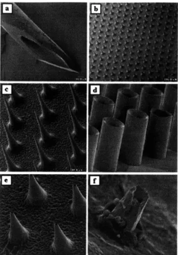
Figure 2.8: Scanning electron micrographs of (a) a 26-gauge hypodermic needle (-460 gm OD), (b) a silicon microneedle array shown at the same magnification as the hypodermic needle and (c) at higher magnification, (d) a hollow metal microtube array, (e) a hollow metal microneedle array, and (f) a tip of a
hollow metal microneedle penetrating up through the underside of human epidermis. These microneedle arrays have been shown to penetrate skin without breaking, increase skin permeability up to 100,000-fold,
and not cause pain in human subjects. (Caption adapted from McAllister et al 2000, pictures from both McAllister et al articles in 1999)
Significant, positive results regarding the success of the hollow microneedles have not been published, and it is believed that BioValve may actually be using a different microneedle approach.
2.2.6 Multi-Test II
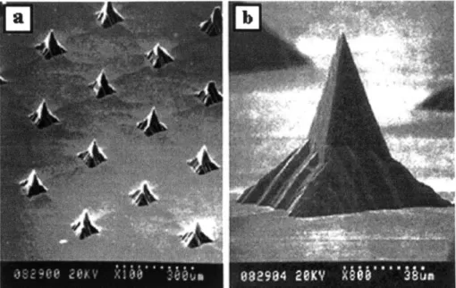
The Multi-Test II, shown in Figure 2.9, multiple skin test applicator (Lincoln Diagnostics, Inc., Decatur, Illinois, US Patent Nos. 5738108 and 5792071) is an excellent example of an established, inexpensive, disposable device that is used to puncture the stratum corneum. This device first dipped in a liquid antigen solution and then pressed on the skin. The tips puncture the stratum corneum and the antigen comes in contact with the interstitial fluid. While it is not used to deliver a controlled liquid volume, as required in the micro-needle project, the effective geometry and low pain sensation during puncturing (Mahan et al, 1993) made the Multi-Test II a helpful starting place for the pyramids created in this project (see Section 4.1.1).
The Multi-Test II has nine pyramids that are inserted into the skin for each antigen. These nine pyramids are approximately 2 mm tall, have an included tip angle of 20*, and are
arranged in a 3 x 3 square with a tip-to-tip spacing of 1 mm in both the x- and y-directions. The Multi-Test II is manufactured via injection molding, and is made of methacrylic.
Figure 2.9: Picture showing the Multi-Test II. The product is used to puncture the stratum corneum in order to deliver liquid antigen to the interstitial fluid.
Figure 2.10: Picture showing the tips of the Multi-Test II. The square pyramids have an included tip angle of 20, and are injection molded out of methacrylic. (Picture using Wilson Chan's setup, see Chan 2002.)
2.3
Other micro-technologies used to deliver drug across the skin
Besides the Georgia Tech system, there are many other micro-technologies used to delivery drugs across the skin that have been and are currently being developed in research labs across the world. The technologies that are potentially applicable to drug delivery are briefly introduced and described below. While it is important to know these technologies exist, it is not critical to spend a lot of time describing the intricacies of each design. Since most are created using time-intensive, expensive manufacturing techniques, they are not readily applicable to the Limpet design.2.3.1 Silicon Microhypodermic Needles for Injection (Lin et al)
human
hair~ooI
Figure 2.11: SEM images of (a) two silicon microhypodermic needles with different shaft lengths shown next to a human hair along with close-up views of the (b) front and (c) top of a microhypodermic needle tip. These needles were developed for injection across skin and have been coupled with bubble pumps and an integrated circuit interface region. (Caption/layout taken from McAllister et al 2000, pictures taken from Lin et al 1993)
0 S S 0 0 S 0 Material: Silicon
Geometry: 140 pim, tapering to 80 pm Length: 1 to 6 mm
Tips: "sharp point"
Injection of drug: 30 x 30 pm port located 150 pm from needle tip Drug delivery: actuated using bubble pump
2.3.2 Microhypodermic polysilicon needles (Talbot and Pisano)
Figure 2.12: Scanning electron micrographs of (a) a single polysilicon microhypodermic needle and (b) a dual microhypodermic needle design developed for drug injection across the skin. (Caption and
layout taken from McAllister et al 2000, pictures originally taken from Talbot and Pisano 1998) " Material: polysilicon
* Geometry 100 to 200 pm in cross-section, 12 to 18 pm walls * Length: I to 6 mm
" Tips: "sharp point"
* Strength: needles reinforced with thin coating of nickel and can withstand moments of <;0.71 mNm
* Injection of drug: 30 x 30 pm port located 150 pm from tip * Delivery of drug: actuated by "bubble pump"
* Manufacturing process: polysilicon is deposited in thin layers onto silicon mold, then annealed
2.3.3 Metallic microhypodermic needles (Brazzle et al)
Structural
/I
Needle Coupling
Ch~annplI
Supports Cantilevered Hollow Micromachined Needles
Si Substrate
Figure 2.13: Diagram showing the design of micromachined metallic needles. (Taken from Brazzle et al 1998)
Figure 2.14: Images showing the manufactured micromachined needles. (Taken from Brazzle et al 1998) " Material: Palladium, gold, or silver
* Geometry:
o 25 needle linear arrays
o 200 gm center-to-center spacing
o Flow channels: 20 gm by 40 gm with a wall thickness of 20 gm o Distance between the needle tips and the structural supports: 250 pam * Pressure drops of 1.03 to 11.03 kPa across 3 mm long channels (600 lam by 30 gm
each) yields water flow rates of 0.83 to 10.83 pL/s
" Structural supports are hollow and in fluid communication with the needles, so
they divert flow from clogged needles into neighboring unclogged needles * Manufacturing process: surface micromachining techniques
2.3.4 Metal needle with multiple output ports
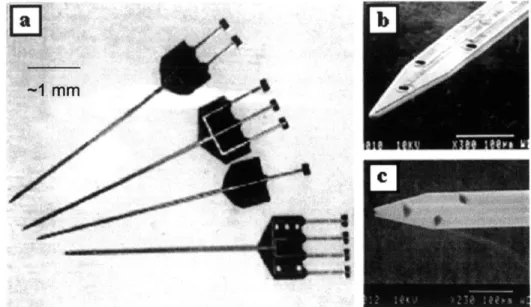
Figure 2.15: Scanning electron micrograph of a metal needle with multiple output ports and a cross-section of the needle showing its microchannel (insert). The multiple ports were designed to reduce the effects of port
clogging. (Caption/layout taken from McAllister et al 2000, original photos taken from Brazzle et al 1999)
" Material: Silicon
" Geometry:
o 6 mm long
o tip dimensions of<15 pm by 15 pm o channel dimensions of 140 gm by 20 pm o shaft dimensions of 200 gm by 60 jm
o distance from tip to first output port of 300 pm
" Pressure drops of 6.9 to 482.6 kPa across 6 mm long channel (140 pm by 20 jm)
with multiple ports (30 jm by 30 pm) yielded flow rates of 67 pL/s to 45 nL/s
2.3.5 Microprobes for DNA injection (Hashmi et al)
Figure 2.16: SEM image showing magnified view of micro-probes used to deliver DNA into plant, nematode, and mammalian cells. (Taken from Hashmi et al 1995)
" Material: Silicon
* Geometry: Square pyramids * Height: 10 to 500 tm
* Tip Radii: < 0.1 im
* Injection of DNA: Molecules to be delivered are coated on microprobes or are in
solution around the cells before microprobe insertion
2.3.6 Glass Microcapillaries (Chun et al)
10 pm 10 pm
Figure 2.17: Images showing glass microcapillaries. Image (b) shows the microcapillaries with plant matter suspended across the tips. (Taken from Chun et al 1999) " Material: Glass and Silicone
* Geometry: 5 pm diameter cylinders * Height: 30 pm
* Tips: blunt, flat cylinder tips
* Injection of DNA: Fluid injected into cells by inserting microcapillaries into cells, then applying a pressure with a syringe-like device
2.3.7 Microfabricated Neural Probes (Chen and Wise)
~1
mm
'I
"I_
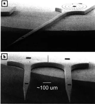
Figure 2.18: Images showing micro-fabricated neural probes used to deliver small amounts of bioactive compounds while simultaneously recording electrical signals. (Taken from Chen and Wise 1997)
* Material: Silicon
* Geometry: 4 mm long, 58 to 74 pm wide shanks * Channels: 10 total, 32 pm wide, 15 pm deep * Liquid volumes: 10 to 100 pL
* 100 ms pulse of nitrogen at 69 Pa forced 87 pL of distilled water through similar
needle
o Manufacturing process: bulk silicon micro-machining (oxidation, boron diffusion, wet-etching steps)
2.4
Fluid delivery in nature: The mosquito
The injection behavior of the mosquito was studied in order to better understand how injection and fluid sampling is done in nature. The mosquito was of particular interest because of its long and narrow proboscis, ability to both inject fluid and remove blood at the same time, and lack of pain associated with the injection of the proboscis.
2.4.1 Mosquito mouthparts
The mosquito's mouthparts are comprised of six stylets, collectively known as the fascicle, encased in a protective sheath, known as the labium. The role of the labium is to
support the fascicle as it is injected into the skin, to cover the fascicle when it is not in use, and to prevent the stylets, which are held together as the fascicle with a viscous fluid, from becoming
dried out. The labium slides back toward the body of the mosquito during fascicle injection, as shown in Figure 2.19. sabiy l stylet Piercing stylets Hypopharynx- x >.
Figure 2.19: Sketches showing mosquitoes injecting their fascicles under the skin. The labia bends toward the root of the fascicle during injection. (Taken from Puppy 2000 (left) and Mosquito Website 2000 (right).)
The fascicle is comprised of six individual stylets, as shown in Figure 2.20, and is approximately 20 to 40 pm in diameter.
Mandibles Labrum
~10 pm
Labium Maxillae
Hypopharynx
Figure 2.20: Sketch showing a cross-sectional view of the mosquito's proboscis. One can see both the labium and the six stylets (labeled) that comprise the fasicle.
(Taken from Clements 1963)
The two maxillae, located on either side of the hypopharynx, are used to pierce the skin. The mandibles, located between the hypopharynx and the labrum, are used to anchor the fascicle into
the skin during penetration, anticoagulant delivery, and sucking of blood. The hypopharynx, with an inner diameter of only 3 pim, is used to inject saliva containing an anticoagulant into skin to stop the clotting of the blood. Most humans have an allergic reaction to the anticoagulant, and
it is this reaction that alerts a bitten human that a mosquito is on his skin. The small size of the fascicle prevents the human from sensing the injection of the mosquito until the allergic reaction occurs. Finally, the labrum-epipharynx is composed of two lamellae to form a 'V'-shaped channel with ventral opening along its length. The hypopharynx fits closely to the ventral surface of the labrum-epipharynx to form a through which the blood is sucked into the mosquito.
All of the mosquito mouthparts have angled tips, presumably to aid in piercing and to prevent
blockage of the tubes.
2.4.2 Sucking blood
The inner diameter of the labrum is approximately 10 to 20 pim, depending on the species. Flow through the tube can be modeled with the Hagen-Poiseulle equation for flow through a cylinder (White 1994, p.3 11), Equation 2.3:
rAP -r4
Q=
r4(2.3),where
Q
[m 3/s] is the volume of liquid flowing through per unit of time, AP [Pa] is the pressuredifference from one end of the tube to the other, r [m] is the inner radius of the tube, pi [kg/m.s] is the viscosity of the fluid, and 1 [m] is the length of the tube. Since the labrum of the mosquito is so small, it takes nearly 5 minutes for a mosquito to suck 5 pl of blood into its stomach, at a rate of approximately 17 nl/s.
2.4.3 Vibration of the fascicle
The mosquito injects the fascicle into the skin by alternately actuating each mandible forward into the skin to anchor it deeper. This action causes a vibration-like actuation of the entire fascicle into the skin. There are many benefits to this method of actuation. First, the mosquito is able to break its fascicle through small sections of skin in short, powerful punches. Second, the backward facing barbs of the mandibles are used to anchor the mosquito fascicle in place so that it does not slip out of the skin during injection or penetration. Finally, the vibration of the fascicle into the skin allows fascicle to "wind" its way into the skin, avoiding obstructions until blood is sensed on chemoreceptors located on tip of fascicle. Many "pierce and suck" insects perform similar vibration injection techniques, and the path of the white fly's fascicle as it is injected into a leaf can be seen in Figure 2.21.
Figure 2.21: Photograph showing the penetration of a white fly's proboscis into a plant leaf. The white dotted line shows the proboscis winding around cells and other obstructions. (Taken from White Fly Website 2000)
2.4.4 Lessons learned from insect injections
Several important lessons can be learned from studying how insects, specifically
mosquitoes, insert their mouthparts into the skin, deliver fluid to and remove fluid from a human. These lessons are summarized below:
" Angled tips are a prominent feature of piercing-sucking insects
" Most insects have stylets that are inserted ahead of the injection/sucking tubes
* Vibration of mouthparts during insertion * Injection/sucking tubes are flexible
* Tubes have thick walls compared with canal diameter * Injection/feeding rates are slow (-17 nl/s)
2.5 Anatomy and physiology of human skin
2.5.1 Structure of human skin
Human skin consists of two primary components: the outer, thinner portion, known as the epidermis, and the inner, thicker, connective tissue, known as the dermis. Beneath the dermis is the subcutaneous layer of skin, also known as the hypodermis.
Hair shaft Dermal papil" Free nsrw end*ng Sebaceous (oil) gland senwy nerve iu r M" otm pa Muscle Hair folla -e Hair root Artory Stratum corneum Stratum lucidum Stratum Ep.. n granulosum Stratum spinosum stratum~ basale Papillary layer Dermis Reticular layerj _ HypomaI Rop hi rW prerw
Figure 2.22: Schematic showing the structure of the skin and
underlying subcutaneous tissue. (Taken from Forever Young Website 2002)
2.5.2 The epidermis
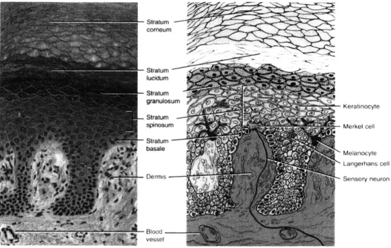
The epidermis is composed of keratinized stratified squamous epithelium and contains four types of cells in a total thickness of approximately 100 Am. The most prevalent type of cell (comprising about 90% of the epidermis) is known as a keratinocyte. This cell goes through the process of keratinization, where cells formed in the basal layers are pushed to the surface of the
skin. As the cells move upward, they accumulate keratin, a protein the helps to protect the skin and underlying tissue. At the same time, the cytoplasm, nucleus, and other organelles within each cell disappear, and the cells die. Eventually, the keratinized cells slough off and are replaced by underlying cells.
There are three other kinds of cells in the epidermis. The first is called a melanocyte, which is also found in the dermis. It produces melanin, one of the pigments responsible for skin color, and absorbs UV radiation. The second kind of cell is called a Langerhans cell, and it functions in immune response within the skin. The final kind of cell within the epidermis is called a Merkel cell. These cells are located in the deepest layer of the epidermis of hairless skin, and are involved in the sensation of touch.
Stratum corneum Stratumlucidum granulosum Keratinocyte Stratum spinsumMerk~el cell basale 0Melanocyte Langerhans cell
Dermis Sensory neuron
-31 lood
vessel
Figure 2.23: A photomicrograph and a corresponding diagram showing the layers of the epidermis. (Taken from Totora 1997)
Four or five distinct layers comprise the epidermis. In most regions of the body, the epidermis has four layers, except for in the on the palms and soles where five layers are recognizable due to the additional stratum lucidum layer. The names for the five layers from deepest to most superficial are:
1. Stratum basale: A single layer of cuboidal to columnar cells that are capable of
continued cell division, also containing melanocytes. The cells in this layer multiply, producing keratinocytes which push upwards to become part of the more superficial layers, mentioned below. The stratum basale also contains Merkel cells that are sensitive to touch.
2. Stratum spinosum: approximately 10 layers of polyhedral cells with spine-like
3. Stratum granulosum: approximately five layers of flattened cells with darkly
staining granules.
4. Stratum lucidum: found only on the thick (1 to 2 mm) skin of the palms and
soles. Consists of approximately five rows of clear, flat, dead cells.
5. Stratum corneum: The top layer of skin, consisting of approximately 30 rows of
flat, dead cells completely filled with keratin. This layer forms a nearly impervious barrier to environmental influences. The thickness of the stratum corneum varies, depending on the location on the body. The stratum corneum of the forehead and cheeks is approximately 20 to 40 ym, while it is approximately 400 to 700 ltm thick on the palms and soles of the feet (Allen 1967).
2.5.3 Drug delivery depth
The desired depth of delivery will vary depending on which drug is administered, and the location of delivery on the body. However, since none of the drugs delivered by this technology are able to penetrate the stratum corneum, the minimum delivery depth must be below this layer. As shown in Figure 2.22, some nerve endings are located just below the epidermis, so it may be desirable to confine the delivery to within the epidermis so that nerve endings are not touched. Most likely, the optimal depth of delivery will depend on the chemical makeup of the drug being delivered, the diffusion rate of the drug at a specific depth, the size of the needles used to deliver the drug, and the desired delivery rate to the patient.
3 Limpet concept
3.1
Design concept
The overall design concept for the Limpet is to have a small, wearable device that can sit securely on the skin for long enough to deliver the required volume of drug over the desired delivery profile. Optimally, the Limpet is so small that its presence is not at all encumbering, and the penetration of the micro-needles and delivery of the drug is not painful to the user. The limpet must be cost-effective for the drugs delivered, must not waste more than 10% of the drug in the delivery process, and must be simple to use.
3.2
Product specifications
It is Norwood Abbey's goal to have the Limpet used with a range of drugs and in a variety of applications. Because of this, it is important to incorporate flexibility into the design so that drug or application changes can be incorporated on the same technology platform. With this in mind, and with consideration given to 1) how mosquitoes deliver and sample fluid from humans, 2) what current biological drug delivery devices are currently on the market, and 3) the
input from the project sponsors, the following product specifications were outlined: * Volume of delivery range: 100 liL to 1 mL
* Rates of delivery: up to 1 yL/s
* Ability to have variable delivery (eg, a lot at the beginning, then maintenance dosing; delivery every hour; delivery on demand)
* Ability to deliver a range of drug types and viscosities * Reduced pain from traditional hypodermic injection * Minimal air injected under skin
* Wasted drug < 10%
* Ability to verify drug, dosing, expiration, etc. with central computer server via the internet
* Geometry that allows for comfortable wear " No uncovered needles
" Possible incorporation of impedance testing to tell depth of penetration " Simple to use
" Increases patient compliance
3.3
Flow of use of the Limpet
The Limpet is intended to be used either at home or in a clinical setting by patients who require the benefits of controlled delivery of biologicals below the stratum corneum. The Limpet must be easy to use so that a patient can use it independently without much training.
The general idea for the Limpet Drug Delivery System is to have the patient purchase a kit that contains an Applicator for properly placing the Limpet on the skin, a set of disposable, filled Limpets that will last for a pre-determined number of doses (e.g., two weeks or one month), and a storage box/docking station for the applicator. If the user has repeated
prescriptions that are delivered using the Limpet Drug Delivery System, they will simply need to purchase a new set of disposable Limpets for the next prescription. The Applicator and
Docking/Storage Kit will be reusable. Some versions of the Limpet may have non-disposable portions (such as the microcontroller and battery) that are reused in order to reduce the cost of the Limpet.
Below is a step-by-step procedure for using the Limpet, including some steps that will not be noticed by the user (such as the impedance testing used to determine the depth of penetration):
* Patient picks up the Applicator
* Patient uses Applicator to pick up the Limpet from kit using an electromagnet (checks on expiration date of drug, patient information, drug interactions, etc., can happen at this point, if incorporated and desired)
" Patient touches the Limpet to the desired delivery location on skin
* Patient pushes button to initiate delivery sequence
* Vacuum in applicator is turned on to pull skin into recesses on bottom of Limpet
" When full vacuum seal is detected with skin, needles are rotated into skin using
motor in Applicator
" If using impedance, when adequate penetration is detected, actuator driving
needles into skin stops -otherwise, hard stop for pre-determined needle penetration is reached
" Applicator is disengaged from Limpet by turning off vacuum and electromagnet
* Pump is started to push drugs into skin (pump may also be started before applicator is removed, especially if power source in applicator is used to give a large current to pump at beginning to quickly initiate flow)
* Drugs are delivered according to pre-determined delivery profile, unless active delivery profile determination is incorporated, such as sampling to determine when next dose is needed (not in current version)
* When delivery is finished, LED or piezo are actuated to inform patient * Applicator is brought to limpet
* Electromagnet is engaged to secure limpet to applicator * Motor in applicator is used to withdraw needles
" Limpet is thrown away (if fully disposable)
4 Limpet Components
There are many components that come together to make the Limpet. This section gives an overview of each of the components, how they interact, and why certain methods,
embodiments, or solutions appear to be optimal at this time.
4.1
Interface between the drug and the human
As described in Sections 2.2 and 2.3, many of the existing biological delivery systems have either needles or pyramids that are injected perpendicular to the surface of the skin. Many needle injections are also done in a similar fashion, although usually with larger needles that penetrate deeper into the skin. Some injections, instead, are performed by injecting a needle just under the surface of the skin at a very small angle. Since both techniques seem to work
adequately, they were both investigated with respect to this project, as described in the sections below.
4.1.1 Pyramids
At the beginning of this project, Norwood Abbey believed that it was optimal to have an array of microneedles, similar to the Georgia Tech array (see Figure 2.1), through which drugs could be delivered to the skin. As the manufacturing process used to create the Georgia Tech array made the array expensive and brittle, less expensive manufacturing techniques were considered.
Several different types of pyramids were created as a possible means for puncturing the skin and delivering drugs. The success of the Multi-Test II in its ability to both puncture the skin and deliver antigens, encouraged the effort to make plastic pyramids, which could be ultimately manufactured by injection molding or some other inexpensive technique.
4.1.1.1 LPKF Prototyping Machine
The LPKF Prototyping Machine (Model 95s/II, Slovenia) was used to create an array of pyramids in poly(methyl methacrylate) (PMMA). A cutting tool with a 600 cutting tip (Kemmer Prizision, Part# E34000750-277020) was used to machine the pyramids at a spindle speed of
50,000 rpm. This technique produced pyramids with smooth edges and good quality tips, as
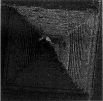
400
pm
Figure 4.1: PMMA pyramids created on the LPKF Rapid Prototyping Machine. Pyramids were cut using a milling tool with a 60* cutting tip at 50,000 rpm. (16 January 2001)
While the tips of the pyramids created via this technique were well formed, the included tip angle was not small enough to easily puncture skin. This machining technique was
discontinued when LPKF machining tools with smaller tip angles could not be found.
4.1.1.2 HAAS Machining Center
The pyramids produced on the LPKF machine were clearly not "sharp" enough to easily puncture human skin. In an effort to determine the optimal included tip angle for puncturing the stratum corneum, a machining technique was needed in which the included tip angle could be changed easily. It was therefore desirable to create a technique that did not depend on the geometry of the tool (as in the LPKF case), but on the orientation of the material during the machining. Additionally, since the pyramids were small and had to be machined with tight tolerances in order to achieve well-aligned tips, it was necessary to use a system in which the piece was clamped into place, and then not moved until completion. A technique was developed for implementation on a 5-axis milling machine, as described below.