AldY
UV
1
I- I'R A
ANALYSIS OF A SIX BAR INTERMITTENT MOTION LINKAGE by
RICHARD ALAN ROSENTHAL
Submitted in partial fulfillment of the require-ments for the degree of Bachelor of Science in
Mech-anical Engineering at the Massachusetts Institute of Technology.
June, 1958
Signature of Author . . . .
Signature redacted
Mechanical Engineering Department,May 26, 1958
Acceptance: Signature of Professor in charge of
Thesis .
.
Signature
redacted
Signature redacted
Signat
.- I- - 41 -1 ure
Cambridge 39, Mass. May 26,
1958
Secretary of the Faculty
Massachusetts Institute of Technology Cambridge 39, Mass.
Dear Sir:
This thesis, entitled "Analysis of a Six Bar Intermittent Motion Linkage," is hereby submitted in partial fulfillment of the requirements for the degree of Bachelor of Science in Mechanical Engin-eering from the Massachusetts Institute of Technology.
Sincerely yours,
Signature redacted
&a~Le c~ ~O~i~Ci ~S
1. Abstract . . . .
2. Purpose . . . .
3.
Introduction . . . .4.
Results and Conclusions . 5. Body of the ThesisAnalysis of the Linkage . . General Comparison of Linkages
Other Devices . . * . . . .. Construction of the Model 6. Appendix
Tabulations for Velocity Curve Photographs of the Model . . Bibliography . . . . . . * . Pg. . . . .14 . . . . 5 . . 0 . 6 . . . . 11 . . 20 a n and * . 0 . 31
.
0 0 034
.
0. .
37
0 0 0 038
0 . 0 041
(3)
A complete kinematic analysis was carried out
on a Six Bar Intermittent Motion Linkage designed
by Mr. Kurt Hain of Braunschweig, Germany. The method used was an indir~et one developed by Prof. T. P.
Goodman of tbae Massachusetts Institute of Technology. The metjoa was found to be easily applicable to this mechanism. The mechanism was found to have a maximum ratio of output velocity to input velocity of 8.61, and of output acceleration to square of input velocity of 23.8. This acceleration is much less favorable than that of the Geneva Wheel. Many interesting advantages of linkages over conventional cams and other mechanisms were discovered and discussed in the report. A working model of the mechanism was con-structed.
The purpose of the investigation undertaken in this thesis was fourfold. First of all it was desired to apply some recently developed methods of mechanism
analysis to an actual linkage and see how they com-pared with already existing methods. Secondly it was desired that this particular linkage be investigated and further studied from the kinematic standpoint. It was thought that the linkage might compare favorably with other mechanisms that produce intermittent motion and it was necessary to undertake the complete analysis to determine whether or not this linkage could compete favorably with such conventional devices as the Geneva Wheel. Thirdly a general study of one particular
linkage was thought necessary to get a broader insight as to the advantages and disadvantages of this type of mechanism as compared with more conventional cams, slider devices, quick return linkages, etc. The
fourth reason was that an actual model of the mechanism was wanted since it would show some interesting
principles of mechanism design and would make a good lecture demonstration for future kinematics courses at the Massachusetts Institute of Technology.
Irb>)CLUC L.Wio
The linkage was designed by Mr. Kurt Hain in Braunschweig, Germany. Mr. Hain is a research eng-ineer at the Institute for Basic Agricultural Research
at Braunschweig. He does a great deal of work in
linkage design and development for use in agricultural machinery although this particular linkage was not
designed for use in any specific piece of equipment. Mr. Hain has written two books on linkage design and engineering and has published over two hundred articles in technical journals. He is considered to be a leader in Vhe mechanisms field in Germany, which
is where most of the advanced work on mechanisms is being done today.
Briefly, the mechanism consists of a six bar linkage driven by a four bar linkage. The four bar linkage serves as a multiplier of the time of dwell, so that the output link of the mechanism dwells, or
is stationary, for 1800 of the uniform rotary motion of the input link.
The complete mechanism is shown in figure 1. This is position 2, when thb input link of the four bar driving linkage has rotated 300 clockwise from
the horizontal. Thus in figure 2, EG,= 300. The four bar driving linkage consists of the input crank
A13, the connectin ILin , , and the output crani wm.
AB rotates with uniform rotary motion about A, and drives CDE with non uniform rotary motion about D. As AB traverses the 1800 of are from position 1
(horizontal, with B to the right of A) clockwise to position 7 (again hbrisontal, with B to the left of A), the output crank CDE traverses only 900 of its total rotation. Then as AB completes the circle swinging across the top half of its travel, CDE also completes a full circle, traversing 2700. Thus both cranks make one complete revolution for each cycle of operation.
Now the six bar follower linkage is driven by crank DE. It consists of . four bar linkage where the i base" is the output link of the mechanism and is fixed or stationary only during the dwell, and two bars added on--one the driving crank DE, and one the base of the mechanism DK. The only stationary points aro D and K. It is easiest to understand the operation of the six bar linkage by looking first at the four bar linkage FGHJ in figure 1. HJ is the "fixed" link and the cranks HG and FJ rotate around H and J respectively. The connecting link is GF. Now when HG begins to rotate about H, the relative lengths of the bars are adjusted such that for part
F
2.
The
%$SxBar
TItermi
Motion Lin.<age,
With
Driving Linkage
G ir\ t3
0G
H
ttent
Fo
ur
Pos
it
Bar
Co n
2
P--MEMOM"o2 the ;motin uo. the liP e -eeleag the connecting link that travels in the arc of a circle about D. This point is point E, and for a portion of the rotation of GH about H, (with HJ
fixed) E rotates in a 900 arc about D. Now if HJ is not held fixed and E is driven in this 900 arc about D, then HJ will remain stationary anyway, since the lengths of the links connecting it with ED are
designed such that this will be so. This then is the essence of the operation of the mechanism--ED rotates in a full circle about D, but for a certain 900 of that circle the link HJK will dwell, whereas for the other 2700 HJK will complete a full circle, rotating about point K. This operation can be verified by studying the model, which works exactly as it has been described here. Pictures of it are found in the appendix. The driving linkage ABCD is related to the driven linkage so that the 900 of motion of crank CDE in which AB is traversing 1800 of its motion are the same 900 in which the link HJK is dwelling or is motionless. Thus HJK does indeed dwell for 1800 of the motion of the input crank AB.
The body of the thesis will consist of a detail-ed report on each of the four points listdetail-ed in the purpose. The Results and Conclusions will come first
with a brif revicw f tie .r0i &L "
used in the actual analysis, arid a summary of the results of that analysis with curves of output velocity and acceleration of the linkage for each point in the cycle. There will be a comparison of
these results with those for a modified Geneva Wheel on which a simimar study was undertaken in 1949. The main report will follow with a complete illustration
of a typical kinematic analysis of the linkage for one point in the cycle. Then there will be a general discussion of the advantages and disadvantages of linkages as opposed to other types of mechanisms that perform similar operations. Finally will be a brief description of the model and its construction.
Results and Conclusions
The method used for the analysis of the mech-anism was developed by Prof. T. P. Goodman of the Massachusetts Institute of Technology in the summer of 1957. It was designed to replace more cumbersome conventional methods for analyses of six bar linkages such as the three line construction, the plan of
relative normal accelerations, or the center of
curvature for one moving point. Briefly, the ab1bi-cation of the method lies in assuming one link fixed and then imposing a velocity on another link relative to the fixed link. If the link which is assumed
fixed is cleverly chosen, the mechanism can then be analysed as a four bar linkage. Then when all the velocities relative to the assumed fixed link are determined, the actual velocities of the mechanism can be found by a system of ratios worked out by Prof. Goodman. The acceleration analysis works similarly, except that the relative accelerations
are related to the actual accelerations by an equation somewhat more complex than a simple ratio. The method was found to be very adaptable to this particular
linkage due to the fact that the six bar linkage could be easily separated into a four bar linkage with two bars added on. Since most six bar linkages can, with greater or lesser degree of difficulty, be
applied to almost all six bar linkages. Since the actual analysis is simply that of a four bar linkage, it is an elementary problem which can be solved by any sophomore student of engineering. The use of Prof. Goodxman's equations is not difficult once it is learned, and with the extra effort required to master the equations a complex six bar linkage can be analyzed using elementary methods. In the actual linkage the analysis broke down in two points due to
a key link reaching a "dead center" position with respect to another link, but this was not the fault of the method used since it was the elementary four bar linkage analysis that broke down. However, in general the method would be applicable to almost any six bar linkage.
The results of the actual analysis are plotted in figures 2, 3, and 4. The analysis described in the previous paragraph was carried out for all positions
for the velocity only. Since the velocities and accelerations during the dwell were not interesting, the analysis was done for the positions at the ends of the dwell, positions 1 and
7,
and for one position during the dwell, 4. For the rest of the cycle the analysis was done for 300 increments of the motionof the input Lri.k AB, and & Dtr o L o
where it was most interesting. The velocity curve was then plotted, and the acceleration curve obtained by differentiating it. A few points on the
acceler-ation curve were checked by going through the complete acceleration analysis for them. The results of the check were found to agree very well with those found from differentiating the velocity curve.
Figure 2 shows the angular velocity of the out-put link HJK divided by the angular velocity of the
input link AB as a function of the position of the input link for clockwise rotation. Note that the highest velocity is reached at position 12.35, and
that the velocity is rapidly changing in this region. The dwell theoretically extends from position 1 to 7, but the curve shows small velocities at both of these
points. In actual practice, these velocities are too small to be detected and may be reduced to zero by play in the bearings. The tabulations for the curve of figure 2 appear in the appendix. They were all
calculated by going through the velocity analysis for each point.
Figure 3 shows the angular acceleration of the output link HJK divided by the square of the angular velocity of the input link as a function of position
Lor clockwise roL'aLkon. U
a L LC;Ja a )
smoothly, but goes to a high positive value very
rapidly, then falls sharply to a large negative value, then returns to zero. Note that the slope of the
acceleration curve is very steep in places. This would make the third derivative or the "jerk" very severe at these points; this is the case as can be verified by working the model. The highest obtained value for the acceleration was approximately -- 23.8, and this is probably the highest actual value in the cycle. The lowest obtained value was -17.3, but there are probably points very near by at which
a somewhat greater negative value is reached. In actual practice however, the acceleration will not exceed this value by much due to play in the links. ThisA is why the acceleration curve was left open
at the bottom, since the maximum neg tive value shown is, probably not the actual maximum, although it is most certainly close.
Figure
4
is a superposition of figures 2 and 3 on the same axis. It is, due to the small scale, not very accurate quantitatively, and just gives a general idea 'of what accelerations correspond to what velocities for the mechanism.Ottp4t
Po'sit ion
Ve
/oc
ity
z
Vs. o f the Linrkae ,Six 6ar .Tntermittentf Motion/2
PO/S 1r1ON2~
Linka<e7
6
wou1 WQIAIS
'32
S1-0
5
6
7
8 8/I
L I / I i+
I L. i-6 t-I I i, I I I I18-riga3
Output Acce/era.tion Vs. Postion of the Linkage
x Bar Inter mctten-t Motion Linkage
12
6-0
7
8 3-9 /0 II IZ PO5 IT/ON-3
-6--3
-12-
-15-I
Il
20
/5
6 7 8 3 tOPXSIT/OA/
'r
Fig 4
Compar-son oflocity
and Acceleratton
C
urves
,.Six
Bar
hitermttenrt
Mo
-on LinkLge
E Ii i 4 CA) II
Z\341
A
c-/0
51-0
-i0
V
it is interesting to compare the Auechanism. witii e modified Geneva Indexing Mechanism as studied by A.C.J.
DiMascio in an S.B. thesis for M.I.T. in 1949. The Geneva Wheel is a somewhat different intermittent motion device than the Six Bar Intermittent Motion
Linkage, as its output dwells for 2700 of the input and moves only 900 in the rest of the cycle, whereas the linkagets output dwells for 1800 of the input and moves a complete 3600 revolution to complete the cycle. Nevertheless, the Geneva Wheel has a maximum ratio
of output to input velocity of
3.77,
whereas the linkage's maximum was 8.6. Thus the linkage would have a less favorable leverage ratio than the Geneva Wheel, and this would make it unsuitable for driving large loads. The maximum ratio of output acceleration to square of input velocity for the Geneva Wheel was13.5, while the same ratio for the linkage was 23.8.
This high acceleration would put the linkage at a dis-advantage when driving large inertias. Of course the two mechanisms do not perform completely analogous functions, as was explained previously, but they both produce intermittent motion from constant motion and
Analysis of the Li
To begin the kinematic analysis of the mech-anism, it was necessary to first analyze the four bar driving linkage. The analysis of this linkage was carried out at all the points where the complete
analysis was desired. The points were chosen in such a way as to reduce the amount of work where possible, and to increase the accuracy in the region where the velocity was changing rapidly. A cardboard model was built first so that this latter region could be
determined qualitatively. Study of the model showed that the region of greatest accelerations would lie between positions 11 and 1. The points for analysis that were finally chosen were 1 (where the input link AB is horizontal with B to the right of A), 4 (right
in the middle of the dwell), 7 (where the input is again horizontal with B to the left of A), and then in 300 intervals of the input links position there-after, namely at points 8, 9, 10, 11, and 12. The analysis broke down at position 9 due to the crank DE reaching a position where it lined up with the base
line DK. In addition, one point was taken between 11 and 12, namely at 11.5, and four points between 12 and 1, namely 12.25, 12.35, 12.5, and 12.7$. The
information obtained from the analyses at these points enabled an accurate velocity curve to be drawn in the
region where it was most interesting.
At each point the four bar driving linkage was analyzed first. A Oypical such analysis is shown in figure 5. This is the analysis of the four bar linkage for position 1. An arbitrary input velocity of the crank AB has been assumed as 10 rad/sec clock-wise. This same input velocity was assumed for all the points where the analysis was carried out. The analysis of the four bar linkage was conventional, the method of velocity components was used rather than that of instant centers, although in some places the latter was used as a check against the former. Thus by requiring that the component of the velocity of B along BC be equal to the component of the velocity of C along BC, the velocity of C was determined. The velocity of E was obtained by using a graphical ratio and is shown as
V.
641 in/sec. Now the actual angular velocity of the crank CDE can be found by dividing:WC- __ 4'Z.(0 X*.O
where the positive sign indicates clockwise motion. Position 1 was one of the positions where the acceleration analysis was carried out also. An arbitrary angular acceleration of the input link of 0 rad/sec2 was assumed and the acceleration analysis carried out using the method of components. The
acz2leratio of PCrl vo to ; vsfo b fzdn the instant center of velocities of BC, and then its angular velocity. The magnitude of the acceleration of E was found to be 1777 in/sec2 in the direction
shown in figure
5.
We are only interested in the tangental component of this acceleration in order to find the angular accele'ation of CDE. By measuring the appropriate ang1q and dividing by the length DE we find:Mrs
7
72. Av k7~
::-.387
%
where the negative sign indicates a counterclockwise acceleration. The velocity and acceleration obtained from the driving linkage will be necessary in the analysis of the six bar followd' linkage, as will be seen shortly.
The kinematic analysis of the six bar linkage for position 1 is shown in figure 6. Finding the position of this linkage for each position of the driving linkage presented a problem at first, but was solved by constructing a very accurate cardboard model of the linkage with the joints held together by pins. For each, position of the driving linkage the orientation of the crank CDE was found, and the model of the six bar linkage rotated to the position where the link DE coincided with its actual position. With point K fixed, the position of every joint in the
C.
f
\C
OC a~o4AA
/0
Kinematic
Analysis of Drtving
LiYk
<ePsit
ion1
\,5ix Bar
Jntermrttent
Motfonnkie
i- d,/s e c.. .
8 7ea
eA
/777 enf ec.ae.C.
C
/ciyaI n 2i~/sec.
--
-
celryin
/nx4-n/ see?
IV,- 64-
i/se
Va
__ __s_ _ _ B
1h ICL b
*
Kinrer
ix C GD
F,6
An./lys
i,
Pos if Fonr oFFo/fowe
r 1Bar
Tntermittent
A
ca. / e's
> Ve/ocity! i --- + Acce.eration:-V
ot on
Link&
?e
Linkage
ir0
i/s
e c. /irk= 400 i rV/se cH
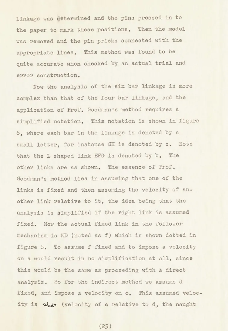
linkage was determined and the pins pressed in to the paper to mark these positions. Then the model was removed and the pin pricks connected with the
appropriate lines. This method was found to be quite accurate when checked by an actual trial and error construction.
Now the analysis of the six bar linkage is more complex than that of the four bar linkage, and the application of Prof. Goodman's method requires a
simplified notation. This notation is shown in figure 6, where each bar in the linkage is denoted by a
small letter, for instance GH is denoted by c. Note that the L shaped link EFG is denoted by b. The other links are as shown. The essence of Prof.
Goodman's method lies in assuming that one of the links is fixed and then assuming the velocity of an-other link relative to it, the idea being that the
analysis is simplified if the right link is assumed fixed. Now the actual fixed link in the follower mechanism is KD (noted as f) which is shown dotted in
figure 6. To assume f fixed and to impose a velocity on a would result in no simplification at all, since this would be the same as proceeding with a direct analysis. So for the indirect method we assume d
fixed, and impose a velocity on c. This assumed veloc-ity is Q(.4* (velocveloc-ity of e relative to d, the naught
Now C, b, e, and d, form an elementary four bar linkage with b as the connecting link. The velocity of F can
thus be found by the method of components, the instant center of velocity of b found, and the velocity of E determined. Now since d was assumed fixed, f cannot be fixed but will rotate around K. The instant center
of a can be found (the velocity of E and the direction of the velocity of D are known), thus the angular
velocity of a is obtained. Now the velocity of D can be found and then the angular velocity of f. Note that all these velocities are relative to d, which is the assumed fixed link. The instant centers are not shown on figure 6 for simplicity, but the velocities of all the points are. With CJ,. o 10 rad/sec, after going through the analysis we find:
with the same notation as to sign as before, i.e. plus is clockwise, minus is counterclockwise. Now what we really know about the linkage is the angular velocity of the crank a relative to the real fixed link f, and not relative to the assum ed fixed link d. From the analysis of the driving linkage:
Note that this is the actual angular velocity so the naught has been dropped. Now the assurmed angular velocity:
a =
0 C W 6-q-.3 +2-4- c. c ea C/
The key principle of Prof. Goodman's method is that the ratio of actual velocities ('4 is equal to the ratio of assumed velocities * This enables us to find the actual angular velocity of c relative to d.
?0?
Now what we are interested in is the actual angular velocity of d (the actual output link) relative to
f (the actual fixed link). We have the assumed velocity:
And by the ratio method we can find the actual velocity.
So this is the answer for the output velocity for position 1. The plot of figure 2 shows the ratio of output velocity of HJK relative to input velocity of the driving crank AB. This was 10 rad/sec, hence:
'AA- -0 r.*
1.60
U;., /0
and this is the value that is plotted on the curve. This same procedure was carried out for all the points where the velocity was found.
The acceleration analysis is somewhat more complex. Link d is again assumed fixed, and an angular accel-eration of c relative to d is assumed. Since zero will work for this assumed acceleration, it is used.
0
The standard four bar linkage analysis is carried
out on dcbe, and the accelerations of the joints found by elementary methods. By the method of components the accelerations of E and D are found, and by vector subtraction the angular acceleration of a relative to d is obtained. Knowing the acceleration of D, the angular aoceleration of f relative to d is obtained.
foo,
It is necessary to be careful with signs here since it is difficult to determine the direction of an acceleration by inspection whereas this method can often be used for velocities. Again plus means clock-wise, minus counterclockwise. Proceeding:
. - -C ( 5'--(41.5' -4?
Now this is the assumed acceleration of a relative to f. From the analysis of the driving linkage we have the actual value:
Cf.
-
-
3 8
7
eC.
The formula for the relation of the actual acceleration to the assumed acceleration is not a simple ratio,
as was the case for the velocities, but is derived in Prof. Goodman's paper (see Bibliography) and, as applied to this situation is:
r /
where r is the ratio of any actual velocity to the assumed velocity.
Z2.77
Remembering that:
we know all the unknowns in the equation except
N.6
~~ ~ 7 ' 2.1 7)4-7 + ( 2 1'7)7-1-.o ,-=
--This is the actual acceleration of the output link d relative to the fixed link f. Note that the sign
dicates that it is in a counterclockwise direction, i.e. is a .deceleration if the mechanism is being driven clockwise. This is what we expect since posi-tion 1 is at the beginning of the dwell when the link-age would be slowing down. The value plotted in fig-ure 3 is this acceleration divided by the square of
the velocity of AB.
And this same analysis was carried out for each point at which the acceleration was calculated.
General Comparison ol Linkages and Uther Devices
Linkages can be designed to perform the functions of many other types of mechanisms. A simple cam could give the same intermittent motion as this linkage, or as the Geneva Wheel. However, the linkages, in general, have many advantages over more conventional devices. This particular linkage is not too advantageous from
the standpoint of velocities and accelerations when compared to the Geneva Wheel, but a linkage could be designed that would have smoother velocity and
accel-eration curves and would, in general, be more advan-tageous. Once designed, a linkage is easier to manu-facture than a cam or other mechanism involving slid-ing surfaces, since the only machined surfaces are the bearings and no milling operation is required. Maintenance would be simpler too for the same reason, there are no followers sliding along machined surfaces that would cause excessive wear--the only maintenance points would be the bearings. For this reason, a simple four bar linkage might advantageously replace a quick return slider in many applications. Perma-nently lubricated bearings would be useful for some places where the loads are not too high, however if the linkage were made very small the incorporation of separate bearings might become difficult. For
tremriely fine ap1icatin. in eLctn n
or time pieces jewdled bearings could be used. Thus the maintenance problem would be reduced to nothing and the advantage of a linkage would be obvious; no slider mechanism could give as trouble free service as a linkage with jeweled bearings.
For other reasons also, many excellent applica% tions of linkages seem to lie in miniature mechanisms. The accelerations and therefore the stresses involved grow with the first power of the size, in smaller components they would be smaller. Where machining a very fine cam to extremely close tolerances would
involve a most difficult operation, building a linkage to perform the task would be comparitavely easy. Of course there is a design problem--a cam can be designed relatively easily to give a desired motion, whereas to get a linkage to produce some complex motion may be quite difficult. This suggests a new field for really clever design work, one where a fertile and ingenious mind could go far.
Where high accelerations and rapidly changing velocities are desired, the linkage has the advantage that it will not jam. In a cam the pressure angle must be kept above a certain minimum, and this limits the acceleration that can be obtained. Also for large negative accelerations a cam requires a heavy return
spring on tue ollower, which serves to increase thLe pressure angle even more during the positive accel-eration part of the cycle. Thus linkages are superior to cams for this type of application.
One other possible advantage of a linkage is that there can be one input with two different outputs.
This is analogous to one cam with two followers, however in the case of one cam with two followers, they both perform the same motion. In a linkage there can be two outputs, each one connected to audifferent link, where both may be performing a necessary function.
For instance if non uniform rotary motion and inter-mittent motion were both desired for a certain
appli-cation, the mechanism analyzed in this.thesis could be used, with outputs connected to crank HJK and crank CDE. In other applications of this kind one linkage could be designed to do two jobs.
Summarizing then, the advantages of linkages over other devices are ease of manufacture, low maintenance and negligible wear, the acceptability of high accel-erations, and the possibility of multiple outputs. The chief disadvantage is the design problem, and the fgct that linkages are not as compact as some other types of mechanisms. But in the general case, linkages are seen to have many advantages that have been over-looked by designers in the past.
Cons ,rution of the 1o.1 .
The advantage of ease of manufacture that was mentioned in the previous section was evident in the
construction of the model. A simple cardboard model had been built previously, and the same size was used because it was ideal for a lecture demonstration and from the standpoint of ease of actual construction. The only shop tools necessary were a metal cutting band saw to cut the links out of 1/8 in. thick sheet aluminum, and a drill press. No. 10/32 machine screws with elastic stopnuts were used at the pivots, with
1/2 in. washers as spacers to prevent the links from rubbing against one another. The mechanism was mounted on a 19 by 16 in. aluminum plate, with the four bar driving linkage on the back and the six bar follower on the front. This enables the viewer to separate the function of the two and to closely follow the motion of the output link, which is the front link in the mechanism. The linkage was mounted vertically for ease of viewing and operation, although the weight of the links makes operation jerky, and rotation in one
direction is easier than rotation in the other. The holes at the joints were drilled carefully and accurately with a drill press and play was kept to a minimum. All sawed surfaces were filed with a
hand file, and all surfaces brushed with emory paper. The mounting plate was attached to a wooden base using aluminum angles. The base was stained and shellacked, and all bearings lubricated with household oil. All the machine screws at the joints were adjusted to cut wobble, i.e. forward and backward play, to a minimum and still permit free rotation. Several photographs of the model appear in the appendix.
L bJul ionz urv. ,l &iur -Position (Degrees) 0
90
180 210 240 270 300 315330
337.5
340.5
345
352.5 Gd4t (Degrees) relative to dwell position 0 0 -1.53.5
2049.5
104143
198264
312(37-)
47
8
9
10 11 11.5 12 12.25 12.35 12.512.75
.603
0 .0542*
329
1.35 2.363.09
7.53
8.61
6.69
2.30
9 b
1W
~4W
4W
fm
Front View of the 1bdel Showing the Six Bar Intermittent Motion Linkage in Position
4..
The Six Bar Follower Linkage in Position 11.5
i -~
Bibliography
Books
1. J. L. Merriam: Mechanics, Part II Dnamics, John
Wiley & Sons Inc., New York,
1951
2. A. Sloane: Engineering Kinematics, The Macmillan Co., New York, 1941
3. Rule & Watts: Engineering Graphics, McGraw Hill Book Co., New York,
1951
Papers
1. T. P. Goodman: An Indirect Method for Determining Accelerations in Cdnmplex Mechanisms, American Society of Mechanical Engineers, New York, 1957
S.B. Thesis
1. A. C. J. DiMascio: Modified Geneva Indexing Mech-anism, S.B. Thesis for M.I.T., 1949