HAL Id: cea-01175471
https://hal-cea.archives-ouvertes.fr/cea-01175471
Submitted on 10 Jul 2015HAL is a multi-disciplinary open access archive for the deposit and dissemination of sci-entific research documents, whether they are pub-lished or not. The documents may come from teaching and research institutions in France or abroad, or from public or private research centers.
L’archive ouverte pluridisciplinaire HAL, est destinée au dépôt et à la diffusion de documents scientifiques de niveau recherche, publiés ou non, émanant des établissements d’enseignement et de recherche français ou étrangers, des laboratoires publics ou privés.
Philippe Garrec
To cite this version:
Philippe Garrec. Design Of An Anthropomorphic Upper Limb Exoskeleton Actuated By Ball-Screws And Cables. Bulletin of the Academy of Sciences of the Ussr - Physical Series, 2010, 72, pp.23. �cea-01175471�
DESIGN OF AN ANTHROPOMORPHIC UPPER LIMB
EXOSKELETON ACTUATED BY BALL-SCREWS AND
CABLES
Philippe GARREC1
Lucrarea prezintă proiectul lui ABLE, un exoschelet al braţului, integral acţionat de un sistem şurub cu cap sferic şi cablu (SSC, de la sistem cu şurub şi cablu), puternic reversibil, care permite controlul real al momentului în articulaţie fără senzor de forţă. Cinematica unică permite integrarea lui în structură graţie inovaţiilor mecanice speciale, precum articulaţia umărului şi încheietura antebraţului. Rezultatul este o arhitectură deschisă, uşoară, antropomorfică, care evită încorsetarea braţului uman. Sunt prezentate pe scurt proiecte de aplicaţii în: recuperarea medicală, telechirurgie şi interfaţare haptică (RV).
This paper presents the design of ABLE, an anthropomorphic upper limb exoskeleton integrally actuated by highly reversible ball-screw and cable (SCS standing for Screw-and-Cable-System) allowing true joint torque control without force sensor. Their unique kinematics allows their integration in the structure thanks to dedicated mechanical innovations such as the shoulder articulation and the forearm-wrist. The result is an anthropomorphic, lightweight, open architecture which avoids imprisoning the human limb. Applicative projects are briefly presented in: medical rehabilitation, teleoperation and haptics (VR).
Keywords: exoskeleton, anthropomorphic design, force control, reversibility, ball-screw, cable, transparency.
1. Introduction
A decade ago, our laboratory developed the screw and cable system (SCS) to motorize a teleoperation tendon-driven force feedback master arm that would be more economical than the MA23 master arm, a pioneering machine originally designed in 1974 by Jean Vertut and his team, also at CEA. This master arm has been since industrialized and is today manufactured by Haption® under the appellation: Virtuose™ 6D 40-40. Shorly after, a second application of this actuator was devised: the force feedback slave arm STeP for radioactive waste disposal inside a well. We then recognized that the SCS could be integrated inside the manipulator’s articulated structure instead of being concentrated at its base.
1
This led to the design of the upper limb exoskeleton, today named ABLE whose design is detailed in this article.
Slave drive unit
Toolbox
Slave arm Slave drive unit
Toolbox
Slave arm
Fig 1. Chronological applications of the SCS actuator : Left, the master arm Virtuose™ 6D 40-40 ; Center, the slave arm STeP ; Right, ABLE 4 axis exoskeleton ABLE
2. Linear torque amplification
The SCS actuator is originally a new answer to the problem of electrical motor torque amplification, a domain pioneered by electrical master-slave manipulators (EMSM) in which our laboratory has been tightly associated [1], [2], [3], [4], [5], [6], [7]. In these types of manipulators, force feedback is simply obtained through mechanical reversibility and a high linearity of the force transfer characteristics. The absence of a torque/force sensor, avoiding drift and calibration procedure, contributes to a high reliability and availability of the machine. Fig 2 shows important pioneering machines typified by their torque amplification principle. Model E1Î circa 1954 (ANL/CRL) Joint transmission cable Motors (multiples) Spur gears Model E1Î circa 1954 (ANL/CRL) Joint transmission cable Motors (multiples) Spur gears Joint transmission cable Motors (multiples) Spur gears MA 23 circa 1974 (CEA/La Calhène) Motor Cabstan (positive) Block-and-tackle Joint transmission cable MA 23 circa 1974 (CEA/La Calhène) Motor Cabstan (positive) Block-and-tackle Joint transmission cable Motor Cabstan (positive) Block-and-tackle Joint transmission cable Hand Controller circa 1990 (JPL) Capstan (adherence) e Joint transmission cable Hand Controller circa 1990 (JPL) Capstan (adherence) e Joint transmission cable Capstan (adherence) Capstan (adherence) e e Joint transmission cable
The first principle has been used by R. Goertz on all his designs from the E1 model (the first servo-manipulator) to the E4 and Model M. Motor torque is amplified using high-precision spur gears driving the joints either directly (translation joints) or, like the scheme shows, through transmission cable (for remote rotation joints). The second is due to J. Vertut and his team for the MA23. Motor torque is amplified using block-and-tackle cable (or tape) arrangements which drives a transmission cable (or tape). The last one, the capstan has been used on the Hand Controller. The cable is wrapped around pulleys to increase the adherence, thus enabling the capstan to transmit more torque with very low tension in the cable resulting in a very low friction threshold. This is today the most sensitive device for torque amplification and it is most commonly found on haptic devices. The single case known to us of a slave arm using capstan is the WAM™ Arm from Barrett Technology®, USA.
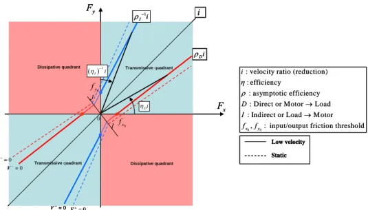
The concept of linear force amplification is best explained using a universal input-output force transfer diagram [8]. Fig 3 is a simplified version for a reversible transmission working at low or null velocity (dry friction).
Dissipative quadrant 0 x f x F i y F I J 0 Transmissive quadrant Transmissive quadrant Dissipative quadrant ( )1 I i η − Di η 0 y f Di ρ 1 I i ρ− 0 V+≈ 0 V+= 0 V−= 0 V−≈ 0 0
: velocity ratio (reduction) : efficiency
: asymptotic efficiency : Direct or Motor Load : Indirect or Load Motor
, : input/output friction threshold
x y i D I f f η ρ → → Low velocity Static Dissipative quadrant 0 x f x F i y F I J 0 Transmissive quadrant Transmissive quadrant Dissipative quadrant ( )1 I i η − Di η 0 y f Di ρ 1 I i ρ− 0 V+≈ 0 V+= 0 V−= 0 V−≈ Dissipative quadrant 0 x f x F i y F I J 0 Transmissive quadrant Transmissive quadrant Dissipative quadrant ( )1 I i η − Di η 0 y f Di ρ 1 I i ρ− 0 V+≈ 0 V+= 0 V−= 0 V−≈ 0 0
: velocity ratio (reduction) : efficiency
: asymptotic efficiency : Direct or Motor Load : Indirect or Load Motor
, : input/output friction threshold
x y i D I f f η ρ → → Low velocity Static Low velocity Static
Fig 3. Force transfer diagrams (case of a reversible transmission)
Input and output efforts (Fx, Fy ) are generalized efforts and the slope “i”
corresponds to the velocity ratio or a strictly linear amplification of forces in absence of friction. For any mechanism comprising an incline (screw, worm gear, etc.), ρ values are potentially different producing an asymmetry. It should also be noticed that the efficiencyη is here equivalent to a force transfer coefficient. This
coefficient is null between the input/output thresholds (dissipative zone) and tends toρ for a maximum input/output force.
Consequently, a linear force amplification will be obtained under the following conditions:
- the input-output friction thresholds must be minimum
- the divergence of the characteristics must be minimum (i.e ρ should be maximum)
- ρD and ρI values should be equal for symmetry purpose
For a high performance mechanism, these constrains must be paired with a low inertia, leading to the concept of a high transparency. These severe constraints explain the challenge encountered by designers.
3. The SCS actuator and its first applications in master-slave teleoperation
In the late nineties our laboratory has designed a new teleoperation, force-feedback, master arm that would be as efficient but less costly than the MA23 (CEA-La Calhène), a machine that has been consistently used in French teleoperation systems since its creation around 1974. This work resulted in the creation of the screw-and-cable transmission or SCS [9] as well as the construction of a prototype of the master arm Virtuose 6D [10].
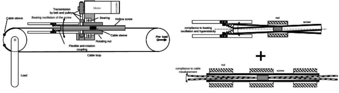
The SCS basic patented principle is presented in Fig 4.
Transmission by belt and pulleys
Motor Hollow screw Rotating nut Cable loop Flexible anti-rotation coupling
Cable sleeve Bearing
Load Cable sleeve Pre- load en co d e r
Beating oscillation of the screw Transmission by belt and pulleys
Motor Hollow screw Rotating nut Cable loop Flexible anti-rotation coupling
Cable sleeve Bearing
Load Cable sleeve Pre- load en co d e r Transmission by belt and pulleys
Motor Hollow screw Rotating nut Cable loop Flexible anti-rotation coupling
Cable sleeve Bearing
Load Cable sleeve Pre- load Pre- load Pre- load en co d e r
Beating oscillation of the screw
compliance to beating oscillation and hyperstaticity
nut screw compliance to cable misalignement screw nut compliance to beating oscillation and hyperstaticity
nut
screw
compliance to beating oscillation and hyperstaticity
nut
screw
compliance to cable
misalignement screw
nut
Fig 4. SCS actuator basic principle
A rotative joint for example is driven by a pre-tensioned push-pull cable. The cable traverses the screw thanks to a bore with enough play to accept some misalignement. The screw translates the cable due to an attached in the middle of the screw. The screw is locked in rotation due to a flexible coupling and pair of rollers circulating in a pair of slots. This solution virtually suppresses the hyperstaticity, guarantees a very low friction and avoids the bulkiness and weight of a linear guiding. The nut rotates in a bearing and can be driven by a belt or by a direct-drive motor. However, the ball-screw (as well as a roller screw) in the
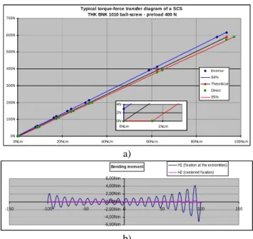
absence of linear guiding tends to oscillate (beating oscillations) in its nut creating an additional cyclic misalignment whch is absorbed by the gap between the cable and the bore. Finally the minimalist and compliant SCS mounting principle almost completely isolates the screw from bending moments and guarantees a low and regular friction. Figure 5 a) presents a torque-force transfer diagram for a typical SCS using a THK BNK 1010 ball-screw (Dia: 10mm ; Lead: 10 mm). Both asymptotic efficiencies (ρD and ρI) are close to 0.94 meaning that the SCS
actuator behaves symmetrically as a high quality gear. The output friction threshold represents approximately 1/1000 of the capacity of the screw. A simulation example (Fig 5 b) shows that the bending moment applied by the cable is approximately reduced 10 times by the central attachment with a equivalent effect on the friction fluctuations. These results explain why the SCS is a competitive solution for joint torque control.
Typical torque-force transfer diagram of a SCS THK BNK 1010 ball-screw - preload 400 N 0N 100N 200N 300N 400N 500N 600N 700N 0Ncm 20Ncm 40Ncm 60Ncm 80Ncm 100Ncm Inverse 94% Theoritical Direct 95% 0N 2N 4N 0Ncm 1Ncm a) Bending m om ent -6,00Nm -4,00Nm -2,00Nm 0,00Nm 2,00Nm 4,00Nm 6,00Nm -150 -100 -50 0 50 100 150
H1 (fixation at the extremities) H2 (centered fixation)
b)
Fig 5. A typical SCS torque-force transfer diagram (a); bending moment reduction due to the centered attachment (b)
The first application of the SCS was the force feedback master arm Virtuose 6D (Fig 6). The first prototype was completed and demonstrated in 2001 at the 9th American Nuclear Society in Seattle.
It combines a classical tendon driven master arm issued from the industrial mechanical telemanipulator MA 30 (La Calhène) with a drive unit using 6 SCS located at its base. Today manufactured by Haption® under the name Virtuose™ 6D 40-40, it is used in teleoperation systems by AREVA and CEA. Shortly after
Virtuose 6D, the SCS was applied to a special type of slave arm drive unit with direct-drive pan-cake motors (Fig 1, center). This force feedback slave arm called STeP (standing for: Système de Téléopération en Puits) was designed to remotely retrieve radioactive material in a well [11].
Screw-cable actuator (SCS)
Actuator unit 6 SCS actuators + gripper actuator
Cable driven manipulator (La Calhène - MA30)
Screw-cable actuator (SCS)
Actuator unit 6 SCS actuators + gripper actuator
Cable driven manipulator (La Calhène - MA30)
Fig 6. Virtuose 6D: the first force feedback master arm powered by ball-screw and cables
4. Design of the upper limb exoskeleton ABLE 4D
In the previous applications of the SCS the advantage of the alignment of the motor with the cable benefited to the compactness of the drive unit. We realized that it was possible process further and integrate the SCS in the moving parts of the arm, reducing the cable length, simplifying its routing and reducing its own friction. To limit the detrimental effect of the increased moving mass - both in terms of gravity torque and inertia - we repositioned the motor near the upstream articulation of the arm using lightweight shafts making use of a pioneering idea [4]. Altogether this combination represented a new tradeoff (Fig 7). Consequently the arm segment of our exoskeleton was designed to pack two SCS, each of them actuating a transversal axis.
Transmission shaft with flexible couplings
Motor
Transmission cable
Anti-rotation slots integrated in the segment
Segment Rollers
Driven limb
Transmission shaft with flexible couplings
Motor
Transmission cable
Anti-rotation slots integrated in the segment
Segment Rollers Driven limb Motor Shaft Ball-screw Transmission cable Rollers Motor Shaft Ball-screw Transmission cable Rollers
Fig 7. Embedded SCS and its application to the arm segment of ABLE
In its embedded version the SCS performs very much like an artificial electrical muscle. As opposed to any of the previous linear torque amplification mechanisms reviewed earlier, it allows a longitudinal motor to drive a transversal
joint without bevel gear. The cable is kept as a joint transmission working at low speed and high force which is favourable to reduce its fatigue. It also brings a lot of well-known advantages: adapted to complex articulation, shock absorption, smoothness, high efficiency. The SCS provides high forces and is highly tolerant to manufacturing incertitude thus adapted to lightweight deformable structures. In terms of relative drawback, the SCS, due to its inherent cable geometry, becomes asymmetrical in stiffness, but only when one of the cable segment looses its tension.
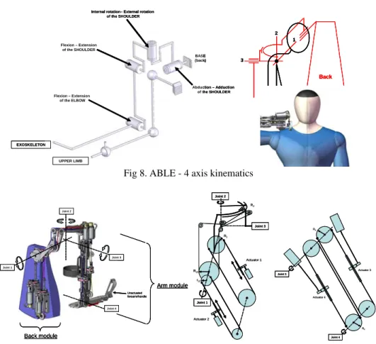
The shoulder joint takes advantage of the SCS to offer a very simple solution to a known difficulty. Its conventional kinematics is shown in Fig 8 with 3 orthogonal, coincident joints forming an equivalent to a knee-pan.
EXOSKELETON
UPPER LIMB
Abduction – Adduction of the SHOULDER Internal rotation– External rotation
of the SHOULDER Flexion – Extension of the SHOULDER Flexion – Extension of the ELBOW BASE (back) EXOSKELETON UPPER LIMB Abduction – Adduction of the SHOULDER Internal rotation– External rotation
of the SHOULDER Flexion – Extension of the SHOULDER Flexion – Extension of the ELBOW BASE (back) Back 1 2 3 Back 1 2 3 Back 1 2 3
Fig 8. ABLE - 4 axis kinematics
Joint 1 Joint 2 Joint 3 Joint 4 Back module Arm module Unactuated forearm/handle Joint 1 Joint 2 Joint 3 Joint 4 Back module Arm module Unactuated forearm/handle Joint 1 Joint 2 Joint 3 Joint 4 Back module Arm module Unactuated forearm/handle r12 R1 R12 R2 I Joint 2 Joint 1 Actuator 1 Actuator 2 Joint 3 r12 R1 R12 R2 I Joint 2 Joint 1 Actuator 1 Actuator 2 Joint 3 Joint 4 Actuator 4 Joint 3 Actuator 3 R4 R3 Joint 4 Actuator 4 Joint 3 Actuator 3 R4 R3
Fig 9. ABLE - 4 axis actuator kinematics: left, back module (Joints 1&2) ; right, arm module (Joints 3&4)
The major difference with respect to previous designs is that the second joint is realized with a circular guide. Such an arrangement is both free of singularity and not too invasive. The first two joints are driven by two SCS attached to the back module whereas the third joint is driven transversally by one of the arm module (Fig 9). The linear coupling between the two first joints is classically decoupled by the control program. The fourth joint drives the elbow. The result is a simple, integrated and morphologically compatible design combined with a distributed actuator mass and volume along the structure.
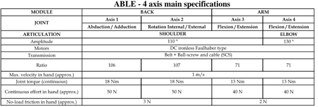
The back module SCS only occupies the half of the back module, to allow the integration of a second exoskeleton in the same volume. The main specifications of ABLE 4D are grouped in Table 1.
Table 1
ABLE - 4 axis main specifications MODULE
Axis 1 Axis 2 Axis 3 Axis 4
Abduction / Adduction Rotation Internal / External Flexion / Extension Flexion / Extension
ARTICULATION ELBOW
Amplitude 130 °
Motors Transmission
Ratio 106 107 71 71
Max. velocity in hand (approx.)
Joint torque (continuous) 18 Nm 18 Nm 13 Nm 13 Nm
Continuous effort in hand (approx.) 50 N 50 N 40 N 40 N
No-load friction in hand (approx.)
BACK ARM
3 N 2 N
SHOULDER
110 °
DC ironless Faulhaber type
JOINT
Belt + Ball-screw and cable (SCS)
1 m/s
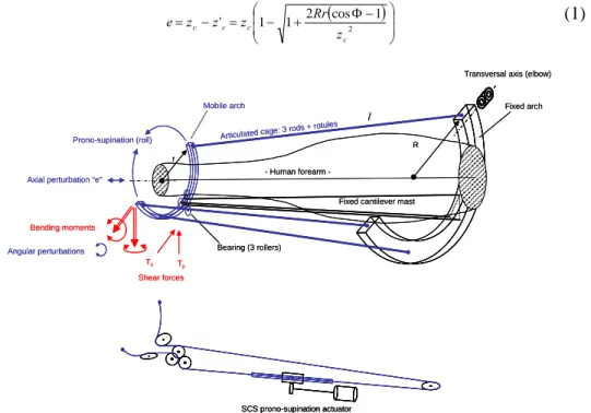
5. Toward ABLE 7D: Design of a forearm-wrist module
The main challenge for us was to design an open forearm structure that would allow sufficient axial rotation amplitude with the capacity to integrate a wrist joint with streamline actuators. We realized that none of the forearm exoskeleton described in the literature [12], [13], [14], [15] addressed these requirements. The result of our reflections was a basic structure (now patented) formed of an articulated cage and a fixed mast ensuring its rotation around an axis due to simple bearings (Fig 10).
Shear forces are balanced by the fixed cantilever mast whereas bending moments are balanced by traction/compression forces in the rods. This decomposition makes the best use of miniature bearings for the required shear forces (about 50 N) whereas lightweight rods/ball-joints can easily transmit the traction/compression forces (about 150 N) necessary to balance the bending moment. Finally, this design presents a better trade-off between volume, weight and friction when compared to a circular guide such as the THK HCR circular ball bearing and it can also be easily scaled. However, the amplitude of the rotation is limited by interferences between rods and fixed parts and the mobile arch presents
a small axial translation (about 6 mm for or a mechanism dimensioned for an average adult) a coupled with its rotation (with the notations in Fig 11):
( ) ⎟ ⎟ ⎠ ⎞ ⎜ ⎜ ⎝ ⎛ Φ− + − = − = ' 1 1 2 cos2 1 c c c c z Rr z z z e (1) Prono-supination (roll) Bearing (3 rollers)
Axial perturbation “e”
Fixed cantilever mast
Ty Tx Bending moments Shear forces Human forearm -Angular perturbations
Articulated cage: 3 rod
s + rotules
l
r
R
Transversal axis (elbow)
Mobile arch Fixed arch
SCS prono-supination actuator
Prono-supination (roll)
Bearing (3 rollers)
Axial perturbation “e”
Fixed cantilever mast
Ty Tx Bending moments Shear forces Human forearm -Angular perturbations
Articulated cage: 3 rod
s + rotules
l
r
R
Transversal axis (elbow)
Mobile arch Fixed arch
SCS prono-supination actuator SCS prono-supination actuator
Fig 10. Basic articulated cage (top) ; SCS prono-supination actuator (bottom)
Fig 11. Kinematic perturbations of the guide
Compared with the flexibility of the skin and muscle, this perturbation is relatively small and it is likely not to be felt by the user. A second cause of perturbation is the offset of the mobile arch (fabrication incertitude, gap and elastic deformation under the load) which induces an oscillation in its plane. In our design, its amplitude is estimated to be kept below 1° which should be again undetectable. The cable transmission brings the necessary tolerance and the level
of torque amplification provided by the SCS is sufficient to avoid any complementary gear.
The precedent structure can be completed with a wrist articulation formed of two transversal orthogonal, coincident axes (equivalent of a conventional U-joint) fixed on the mobile arch. Each of the joints is driven by a SCS mounted on a structure that replaces one of the rods (Fig 12). Both a linear and a non linear decoupling are necessary for the control of this structure.
Abduction-Adduction SCS drive
Flexion-Extension
Abduction-Adduction Flexion-Extension SCS drive
Structure replacing one of the rods Two orthogonal axis
J
Abduction-Adduction SCS drive
Flexion-Extension
Abduction-Adduction Flexion-Extension SCS drive
Structure replacing one of the rods Two orthogonal axis
J
Fig 12. Wrist 2 axis articulation and SCS drives with their respective cable routing
The synergy of SCS actuators with the articulated cage is obvious: motors are aligned with the rods and their reflected inertia is reduced because they are located close to the base. In the other hand, the heterogeneous linking devices on the mobile arch (two ball-joints and a pair of orthogonal axis) generate some other angular perturbations but fortunately of a low magnitude (below 1° for our design). The main specifications of the forearm-wrist module are regrouped in
Table 2.
Table 2
Forearm-wrist main specifications MODULE
Axis 5 Axis 6 Axis 7
Prono-supination Abduction-Adduction Flexion / Extension
ARTICULATION
Amplitude Motors Transmission
Ratio 117 49 47
Max. velocity in hand (notional)
Joint torque (continuous) 2 Nm 2 Nm 2 Nm
Continuous effort in hand (approx.) 19 N 22 N 20 N
No-load friction in hand (approx.) 0 N 0 N
JOINT/ARTICULATION
FOREARM-WRIST
FOREARM
Belt + Ball-screw and cable (SCS) DC ironless Faulhaber type
110°
1 m/s
6. Conclusion
The SCS actuator developed and applied in master slave teleoperation a decade ago has been successfully integrated in the architecture of the upper limb exoskeleton ABLE leading to an open and anthropomorphic machine capable of true joint torque control. However, some development work is still undergoing on
adjustable segments and on the optimization of the shoulder (suppression of the circular guide and improvement of its working volume). The prototype ABLE 4D is already undergoing evaluation tests in rehabilitation within the national project ANR-BRAHMA [16]. A 7 axis version (Fig 13) is expected in 2010 for teleoperation (nuclear) and haptics (automotive industry) applicative projects. The exoskeleton could then become a universal master device with important cost benefits and diffusion consequences. SCS actuators have also a large potential of applications in anthropomorphic embedded assistive slave arms, biped robots and low limb exoskeletons. Other industrial applications may be envisioned to assist workers and reduce musculoskeletal disorders.
Fig 13. A possible view of ABLE - 7 axis
R E F E R E N C E S
[1]. R. C. Goertz et al., Master-Slave Servo-Manipulator Model 2, Proc.4th Ann. Conf. Hot Lab. And Equip. 1, 1955
[2]. Galbiati et al., A Compact Flexible Servo System for Master Slave Electric Manipulator, 1964
[3]. C. R. Flatau, Development of Servo Manipulators for High Energy Accelerator Requirements’ Proc. 13th Conf.Remote Sist. Technolol., 29, 1965
[4]. C. R. Flatau, J. Vertut, MA22-A compact bilateral servo master-slave manipulator, Proc. of 20th Conf. on Remote Systems Tech., 1972
[5]. J. Vertut, and al.,Bilateral Servo Manipulator MA23 in Direct Mode and Via Optimized Computer Control 2nd Remotely Manned Syst. Technol.Conf., 1975
[6]. G.-W. Köhler, Manipulator Type Book , Verlag Karl Thiemig, München, 1981
[7]. J. Vertut, P. Coiffet, Téléopération Evolution des techniques, vol. 3A, Hermes, Paris France, 1984
[8]. P. Garrec, Systèmes mécaniques, in: Coiffet. P et Kheddar A., Téléopération et télérobotique, Ch 2., Hermes, Paris, France, 2002
[9]. P. Garrec, French Patent: Transmission à vis, écrou et câble attaché à la vis for screw and nut transmission and cable - FR0101630, 2000 (EUR 01938347.0-2421 and US 10/296,740
[10]. P. Garrec, J.P. Friconneau, F. Louveau, Virtuose 6D: A new force-control master arm using innovative ball-screw actuators, in Proceedings of ISIR 35th International Symposium in Robotics, Paris, March 2004
[11]. J.M. Goubot, P. Garrec, STeP: an innovative teleoperation system for decommissioning operations, Workshop Decommissioning challenges: An industrial reality ?, French Nuclear Energy Society, 23-28 November 2003, Avignon, France
[12]. M. Bergamasco, B. Allotta, L. Bosio, L. Ferretti, G. Parrini, G. M. Prisco, F. Salsedo, and
G. Sartini, An arm exoskeleton system for teleoperation and virtual environments
applications, in Proc. IEEE Int. Conf. Robot. Autom., vol. 2, 1994, pp. 1449–1454
[13]. A. Gupta, M.K. O'Malley, Design of a haptic arm exoskeleton for training and rehabilitation, Mechatronics, IEEE/ASME Transactions on Volume 11, Issue 3, June 2006 Page(s):280 – 289
[14]. L. Frisoli, A. Borelli, Montagner, et al.,Arm rehabilitation with a robotic exoskeleleton in Virtual Reality, Proc. of IEEE ICORR 2007, Intern. Conf. On Rehabilitation Robotics [15]. J.C. Perry, J. Rosen, S. Burns,Upper-Limb Powered Exoskeleton Design, IEEE/ASME
Transactions on Mechatronics, Volume 12, Issue 4, Aug. 2007 Page(s):408 – 417
[16]. N. Jarrassé, J. Robertson, P. Garrec, J. Paik, V. Pasqui, Y. Perrot, A. Roby-Brami, D.
Wang, G. Morel, Design and acceptability assessment of a new reversible orthosis,
Proceedings of IROS 2008, September 2008, Nice, France
[17]. P. Garrec, J.P. Martins, J.P. Friconneau, A new Technology for Portable Exoskeletons, AMSE 2004 – Vol. 65 n° 7/8, pp 13-22.
[18]. P. Garrec, J.P. Martins, F. Gravez, Y. Perrot, Y. Measson, A New Force-Feedback, Morphologically Inspired Portable Exoskeleton Proceedings of 15th IEEE International Symposium on Robot and Human Interactive Communication (RO-MAN - 2006), September 2006, Hatfield, UK.
[19]. P. Garrec, F. Geffard, Y. Perrot (CEA List), G. Piolain, A.G. Freudenreich (AREVA/NC La
Hague), Evaluation tests of the telerobotic system MT200-TAO in AREVA-NC/La Hague
hot-cells, ENC 2007, Brussels, Belgium, September 2007
[20]. P. Garrec, J.P. Friconneau, Y. Méasson, Y. Perrot, ABLE, an Innovative Transparent Exoskeleton for the Upper-Limb, Proceedings of IROS 2008, September 2008, Nice, France