Publisher’s version / Version de l'éditeur:
Vous avez des questions? Nous pouvons vous aider. Pour communiquer directement avec un auteur, consultez la
première page de la revue dans laquelle son article a été publié afin de trouver ses coordonnées. Si vous n’arrivez pas à les repérer, communiquez avec nous à [email protected].
Questions? Contact the NRC Publications Archive team at
[email protected]. If you wish to email the authors directly, please see the first page of the publication for their contact information.
https://publications-cnrc.canada.ca/fra/droits
L’accès à ce site Web et l’utilisation de son contenu sont assujettis aux conditions présentées dans le site LISEZ CES CONDITIONS ATTENTIVEMENT AVANT D’UTILISER CE SITE WEB.
Canadian Building Digest, 1972-06
READ THESE TERMS AND CONDITIONS CAREFULLY BEFORE USING THIS WEBSITE.
https://nrc-publications.canada.ca/eng/copyright
NRC Publications Archive Record / Notice des Archives des publications du CNRC :
https://nrc-publications.canada.ca/eng/view/object/?id=68025695-e9fe-4549-b801-f8e04af81f8d
https://publications-cnrc.canada.ca/fra/voir/objet/?id=68025695-e9fe-4549-b801-f8e04af81f8d
NRC Publications Archive
Archives des publications du CNRC
For the publisher’s version, please access the DOI link below./ Pour consulter la version de l’éditeur, utilisez le lien DOI ci-dessous.
https://doi.org/10.4224/40000786
Access and use of this website and the material on it are subject to the Terms and Conditions set forth at
Protected-membrane roofs
Canadian Building Digest
Division of Building Research, National Research Council Canada
CBD 150
Protected-Membrane Roofs
Originally published June 1972 M.C. Baker, C.P. Hedlin
Please note
This publication is a part of a discontinued series and is archived here as an historical reference. Readers should consult design and regulatory experts for guidance on the applicability of the information to current construction practice.
It has been said that roofs are so necessary to man's very existence that much of his struggle here on earth is devoted simply to keeping a roof over his head. It took thousands of years for the evolution of the windbreak or lean-to form of shelter to emerge, and traditional sloped roofs are, to the present day, merely an extension of this type of construction.
For the past hundred years man has been trying to build roofs with little or no slope and for the last fifty has been insulating roofs to control heat loss. Traditional sloped roofs usually give good service because the details of design and application are well known from experience. Modern flat roofs, on the other hand, often give extremely poor service. If their performance is to be improved and their service life extended, it is necessary that all concerned with design and construction understand the elements of a roof system and the requirements of each element. Only in this way can materials be put together in the optimum manner.
Roofing Systems
A modern roof system has to perform a variety of functions in separating indoor and outdoor environments. Particularly important are the ability to protect a building against entry of moisture and the provision of effective thermal insulation. The system will normally include
a structural roof deck,
an air-vapour control element,
insulation (heat control element), and
watershedding or waterproof roofing (rain control).
It does not much matter how these are combined with respect to heat loss, but their relative locations have a considerable effect on the performance of the individual elements.
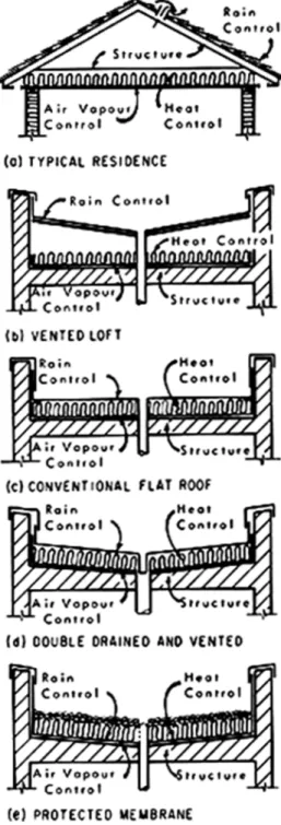
For the typical, sloping residential roof the joists and rafters or roof trusses together with the roof sheathing provide the structural deck (Figure 1a). An air vapour barrier is usually provided at the ceiling, with insulation laid between the ceiling joists and watershedding overlapping units such as shingles applied to the sheathing. The air space between the top of the insulation and the underside of the sheathing is generally ventilated to the exterior. This type of system has been eminently successful, and when problems develop they are usually due to a poor air barrier at the ceiling combined with inadequate ventilation. The same arrangement of elements
has been successfully used for buildings other than residences with a secondary deck sloped to internal drains (Figure 1b). The air barrier at the ceiling retards moisture flow from inside the building, but small amounts that penetrate to the attic space pass harmlessly to the outside.
Figure 1. Roofing Systems.
Most commercial and industrial buildings with flat or nearly flat roofs have a different arrangement of elements (Figure 1c). An air vapour barrier is laid on top of the structural deck and insulation is applied over it, usually adhering to it. This is a very convenient way to build a roof because the structural deck provides support for the air vapour barrier and insulation during construction and in service. The air vapour barrier is placed inward of the insulation to prevent building moisture from penetrating to the cold parts of the system by diffusion or air
leakage. Rain control is provided as the most outward element of the system and consists of a waterproof membrane to withstand all aspects of the weather.
Such flat-roof systems have some basic disadvantages. The roofing membrane is subjected to the full onslaught of the weather and has to endure high and low temperatures and a wide range of daily and seasonal temperature variations. Lack of slope or inadequate slope to compensate for deflection of structural elements allows water to pond. The fact that the insulation is sandwiched between two membranes, the air vapour barrier and the roofing membrane, produces a vapour and water trap. Successful roof systems of this sort can be built if design is adequate, dry materials are used, good weather conditions prevail during application, and careful workmanship is provided throughout the job. Failures of such systems over the years since they were introduced, however, have been sufficient in number to indicate a need for a different approach.
Possibility of failure can be reduced by providing slopes for drainage and eliminating the water/vapour trap (Figure 1d). This can be achieved by a double drained and vented system (CBD 99) designed to remove water entering the system from any source. This system has been used successfully on many roofs.
Protected Membrane Roofs
More recently, and particularly for roof terrace systems, a new approach has been suggested. This type of roof has been given a variety of names such as upside down, inverted, insulated membrane and protected membrane. The system is simply a rearrangement of the normal elements of a roofing system to overcome some of the disadvantages of conventional arrangements (Figure 1e). The air vapour barrier and the roofing membrane are combined on the sloped structural deck, with the insulation located on the outside of the membrane like the fur on the skin of an animal. Any moisture that penetrates the membrane from inside the structure can more easily evaporate to the outside; and precipitation that falls on the exposed insulation drains over or through it, also evaporating when conditions are suitable.
The protected membrane principle of a structural deck sloped to drainage, with a roofing membrane applied on top and insulation placed outward of the membrane, is very simple, but there are details and ramifications that require consideration if the full potential of the system is to be realized.
1. The structural deck must provide continuous support and a reasonably smooth surface for application of the membrane. Corrugated decks such as steel require sheet steel, plywood, gypsum board, or concrete fill to provide a suitable surface. All deck surfaces should be designed to provide positive slopes to drains, and all materials above the membrane on the deck should be arranged to facilitate drainage. The minimum practicable slope is about ¼ inch per foot.
2. Any membrane that has proved satisfactory for conventional systems can be used; some waterproofing systems not suitable as exposed roofing can serve in protected membrane systems. If layers of bituminous felt and bitumen are used to construct the membrane, shingle type application should be avoided. Separate layer or a modification of separate layer application is recommended, as described in CBD 95. The membrane in most cases will require intermittent attachment to the deck to avoid any danger of splitting from deck cracking or movement. Spot attachment using specially prepared proprietary felts can achieve this. Thick waterproof coatings such as rubberized asphalts that do not use felts for reinforcement are normally applied with continuous attachment to the deck. Proponents claim that full adhesion limits lateral movement of water between the waterproof membrane and the deck, should the membrane be punctured. This is undoubtedly so if complete adhesion is achieved, and it might make leaks easier to find.
The important thing is that the membrane remain intact. For more rigid, felt-type membranes intermittent attachment is required so that strains can be reduced below the critical level. Nonhardening, flexible membranes without felts will take up movement by thinning out, and provided they are thick enough and cohesive enough will not break.
3. Ideally, insulation should be nonabsorptive of water, durable to weather, and reasonably stable dimensionally. It must be adequately fastened to the membrane by an adhesive bond or held in place by ballasting against wind uplift and flotation. Wen protected membrane arrangements are used in roof terrace or podium systems the traffic surfacing and landscaping materials usually provide more than sufficient ballasting and protect the insulation against mechanical damage and ultra-violet deterioration.
Some plastic insulations otherwise suitable for protected membrane roofs are subject to deterioration if exposed to radiation. Paint coatings might be considered adequate protection against ultra-violet but they will not guard against damage from hail or traffic, and uplift and flotation resistance must be provided by the adhesive bond between the insulation and the membrane and between the membrane and the deck. The effectiveness of the adhesive will depend on the smoothness, cleanness and dryness of the deck and membrane and on the care of application. It may be wise to consider ballasting by gravel or concrete slabs for all protected membrane roofs. Corners and edges of buildings, which are particularly vulnerable to wind uplift, should be ballasted even where the remainder of a paint protected insulation surface is exposed.
Effect of Water on Insulation
Thermal, structural, drainage and surfacing considerations for roof terraces were discussed in some detail in CBD 75. The implications of water in contact with insulation, draining over and through it, will now be discussed. The protected membrane system often employs preformed insulation with more or less open butt joints. In many current designs most of the precipitation may be drained off by the top protective cover or along the top surface of the insulation, depending on the tightness of the butt joints and the slope of the top cover and insulation. Some water, however, will probably find its way to the impermeable membrane, by way of the butt joints, and thence to the drains. Under these circumstances the insulation will be exposed to moisture on all sides -- the top to precipitation or snow melt water falling on or draining over it, the edges to water draining through the joints, and the underside to water penetrating between the insulation and the underlying system. This can occur even in adhered insulation systems where adherence is not complete. Where there is no slope or inadequate slope, where there are depressed areas or blocked drains and drainage paths water will pond in the joints. Water will also lie under boards where adherence is incomplete.
Under these very severe conditions most insulations will tend to gain moisture by absorption or water vapour transfer, and this will affect to some degree their insulating effectiveness and physical stability. Some insulations may gain a great deal of moisture. This will severely limit the number of suitable insulations and will eliminate most insulations that are commonly used in building construction unless something can be done to maintain a low moisture content. Design must promote a favourable ratio between the potential for moisture loss and the potential for moisture gain by insulation. This is naturally a desirable aim even for insulations not greatly affected by moisture.
The severity of the exposure of an insulation to moisture can be influenced by the drainage provided. The first requirement for good drainage is decks and membranes sloped to drains, as already stressed. It is sometimes considered that sufficient drainage will occur at the membrane through normally applied butt joints, but this leaves drainage to chance. Drainage at the membrane, below the insulation, can be facilitated by drainage channels. Chamfered edges on insulation should usually be sufficient to accomplish this. As the temperature under the insulation will be close to the interior temperature, drainage will take place even during the coldest outside weather conditions.
The temperature at the membrane under the open joints of the insulation should normally be only a few degrees colder than that under the insulation. Laboratory tests have been conducted using polystyrene insulation and joints purposely separated to ¼-inch width over a variety of decks and under dry and wet conditions. Wet conditions were simulated by filling the joints with water; outside temperature was -30°F while inside temperature was 80°F. Temperatures
measured at the membrane under the open joint and under the insulation showed differences of from 1 to 3 degrees for dry conditions and from 3 to 7 degrees for wet conditions for thicknesses of insulation up to 1 ¼ inch. For greater thickness of insulation and smaller width of joints it should be considerably less.
Clogged drains or occasional high rates of precipitation may result in flooding of the deck and immersion of the insulation in water, a condition that could have serious consequences for porous types of insulation. Even when non-porous insulations have been used, the chances of water penetration around flashing details may be great and flotation of the insulation a problem. Suitable deck slope and adequate drain capacity are essential. In some cases supplementary drains such as wall scuppers should be considered for emergency situations. A layer of gravel beneath insulation provides a temporary storage space for water until it can drain away. It can also be used as a levelling course for surfacing materials above a sloped structural deck. This will usually ensure that the insulation is not immersed in water, but ballast must be provided for the insulation in such a system. Airflow through the protective cover and ballast to the space below the insulation may tend to reduce the heat control value of insulation. with normal joints between slab-type surfacing and closure at the perimeter by parapet walls or others means, the additional heat loss should not be significant.
If insulation does become wet, it will have to dry mainly by evaporation. Consideration has to be given to providing for drying forces that can act effectively. The water vapour pressure in the insulation must exceed that of the outside air, and during much of the year in most parts of Canada this will be the situation. During the winter, heat from the building keeps the insulation warm, thus producing conditions that drive moisture outward. Even in summer, conditions favourable to drying will often prevail, although humidity varies with geographic location from low in the prairies to higher in west coast and eastern regions of Canada. An unobstructed path must be provided for the escape of water vapour. Any continuous top covering in direct contact with the upper surface of the insulation, for example paving slabs, paint or other low permeability material, will impede the escape of vapour and may cause it to recondense in the insulation. Open coverings such as gravel or paving slabs that are elevated to provide ventilated space above the insulation surface will permit drying.
Summary
It must be realized that the performance of a protected membrane system is related to a single membrane that serves as both air vapour barrier and water barrier. It must be continuous and waterproof from installation throughout its service life. It is in a favourable environment in relation to temperature and weather and will usually outlast the insulation, which can largely deteriorate before the membrane will be affected. The life of insulation can be extended by designs that allow for drainage and evaporation of moisture from all sources.