SHIP )ESI(N
by
Markos Nicolaos Vassilikos
B.S. Marine Engineering, Hellenic Naval Academy, 1981
SUBMITTED TO THE DEPARTMENT OF OCEAN ENGINEERING IN PARTIAL FULFILLMENT OF THE
REQUIREMENTS FOR THE DEGREES OF OCEAN ENGINEER
and
MASTER OF SCIENCE IN OCEAN SYSTEMS MANAGEMENT
at the
MASSACHUSETTS INSTITUTE OF TECHNOLOGY
May 1989
Copyright (c) Markos Nicolaos Vassilikos, 1989. All rights reserved The author hereby grants to MIT penrmission to r duc nd to
distribute copies of this thesis document in whQe [orin[part.
Signature of Author
Depart ent t: Ocean Engineering May 12,1989
Certified by
Certified by
tL/'"--- -- - Professor Paul. E. Sullivan Thesis Supervisor
_ w
4V
Ocean Systems
Professor Henry. S. Marcus
Management, Thesis Reader
Accepted by
Professor A. Douglas Carmichael, Chairman Ocean Engineering Department Committee on Graduate Students
JUN 15 1989
NAVAL VEHICLES AND DISPLACEMENT-HULL NAVAL
SHIP DESIGN by
Markos Nicolaos Vassilikos
Submitted to the Department of Ocean Engineering on May 12, 1989 in partial fulfillment of the requirements for the degrees of Ocean Engineer and
Master of Science in Ocean Systems Management.
Abstract
A small naval ship, derives its desirability as a naval vessel, due to the fact that it is an inexpensive solution to the problem of maritime defense. This thesis compares five of these naval vessels, two displacement-hull form, two hydrofoils, and one Surface Effect Ship. The procedure of the comparative analysis begins with a comparison of the gross characteristics of the ships, and uses several design indices to examine the factors that influenced each design. Differences in design criteria, standards, and practices are identified and assessed, and the advantages and disadvantages of each design are presented.
Thesis Supervisor: Title:
Professor Paul. E. Sullivan
A L c pc6V CE
cr ae "TOV 1' TmT-EpC Louj KCOL,
I.
~pc~s
Zrl~r
I~O~,
Dedi cat ed t o my f at her, and to t he memory mot her.
of my
ACKNOWLEDGMENTS
I would like to thank the Hellenic Navy for
my three years of
sponsoring
st udi es i n t he U.S.
Al I the members of the MIT faculty who have
contributed to my education.
My academic advisors Professors Cl ark Graham,
Tibbitts, and Paul Sullivan for passing to me t hei r
experience and insight. Paul Sullivan my thesis advisor for his technical supervision and constructive advice.
Professor Henry Marcus, who has taught me how to
make a good group, usi ng i nst i gat i on w i t hout i nterventions.
Dr Theodosi s Bouf ounos, prof essor in the Hellenic
Naval Academy, for t'he inspiration he has given me.
My friend Takis Alourdas a senior officer in the
Helleni c Navy, for the fruitful "compet i t i on", cooperation
and conversations through the last twelve years.
Esther who suffered through t he progress
this work, and all my beloved friends who made all MIT years really happy.
Barrick
Fi nal I y, of
TABLE OF CONTENTS Title page Abst ract Acknowledgements List of tables List of figures Chapter 1
- Introduction
1.1 Purpose of the study
1 .2 Rationale for ship selection
1.3 St udy approach
1 .4 Sources for the study
Chapter 2 History of small combatants
2.1 The pl ani ng hul I form and HSD vessels
2.2 The hydrofoils
2.3 The SESs
Gross ship description
1 2 3 11 12 16 16 16 19 20 21 22 24 24 Chapt er 3 26
Chapter 4 - Overall analysis of ships 4.1 Gross characteristics 4.1.1 The CPIC 4.1.2 The SPICA i 4.1.3 The PHM 4.1.4 The M161 4.1.5 The APB34 4.2 Comparison by weights 4.2.1 Weight allocation 4.2.1.1 SWBS Group 100 4.2.1.2 SWBS Group 200 4.2.1.3 SWBS Group 300 4.2.1.4 SWBS Group 400 Survei II ance) 4.2.1.5 SWBS Group 500 4.2.1.6. SWBS Group 600 4.2.1.7 SWBS Group 700 4.2.1 4.2.2 4.3 4.3.1
fraction
(Hull St ruct ures) (Propulsion Plant)
(Electric Plant)
(Command and
(Auxiliary systems)
(Out. and furnishings)
(Armament)
.8 Loads and margins fraction
Absol ute scale weight s
Volume comparison Mission support (V1) 33 33 33 36 36 37 37 38 38 38 38 39 39 39 40 40 41 41 41 42
4.3.2 4.3.3 4.3.4 4.4 4.4.1 4.4.2 4.4.3 4.4.4 4.5 Personnel support (V2) Ship support (V3)
Ship mobility system (V4) Weather deck pace comparison
Weapons/ Sensors fraction Superstructure fraction
Boat s and repl eni shment at sea f ract i on
I nt ake and exhaust f ract i on
Chapter conclusions
5 - Design indices by f unct ional area Mobi I ity
.1 Speed
.1 .1 Hydrodynami c ef f i ci ency
.1.1 a Propulsive coefficient .1.1 b Lift to drag ratio
.1.2 Mai n propul sion weight specif ic rat i o
.1.3 Design budget .1.4 Conclusions .2 Range .2.1 Stores endurance 42 43 43 44 44 45 45 45 46 49 50 50 52 52 53 55 56 56 60 60 Chapter 5.1 5.1 5.1 5.1 5.1 5.1 5.1 5.1 5.1 5.1
5.1.2.2 Fuel endurance 60
5.1.2.3 Conclusions 62
5.1.3 Seakeeping 64
5.1.3.1 Maneuverability 71
5.1.3.2 Conclusions 72
5.1.4 Propulsion system design integration 73
5.1.4.1 Prime movers 76
5.1.4.2 Transmissions 77
5.1.4.3 Propulsors 78
5.1.4.4 Vol ume al I ocat i on 79
5.1.4.5. Survivability 80
5.1.4.6 Operability 81
5.1.4.7 Conclusions 81
5.2 Structural design practice 87
5.2.1 SES st ruct ural design pract ice 87
5.2.2 Hydrofoil structural design practice 89
5.2.3 Structural materials 90
5.2.4 Structural weight analysis 92
5.2.5 Conclusions 96
5.3 Electrical power 101
Command and surveill ance
Shi p oper at i ons Auxiliary systems
Outf i t and f urni shi ngs
Personnel Chapter 5 summary Chapt er 6.1 6.2 6.3 Chap 6.- Producibility
Conventional hull and SES producibility Hydrofoil producibility
Summary
ter 7 - Conclusion 7.1 Lessons learned
7.1.1 Attributes and limitations of the (PHM and M1 61)
7.1.2 Attributes and limitations of APB3
7.1.3 Attributes and limitations of the
(CPiC and SPICA II)
7.2 Recommendat ions for f urt her study
126 1 26 127 132 133 .133 iydrof oils 134 14 135 nonohul I s 137 138 Bibliography 5.4.1 5.4.2 5.5 5.6 5.7 5.8 107 107 113 114 120 121 139
Appendix A
Appendix B
Appendix C
U.S. Navy Wei ght Cl assi f i cat i on
U.S. Navy Space Classi f i cat ion
Design i ndex I i sti ng
143 146 148
LIST OF TABLES
Gross char act eri st ics Payload
Speed charact eri st ics
Design integration parameters Structural parameters
Group 100 weight
Electrical power Payload
Ship operat ions
Auxiliaries
Personnel 4.1 4.2 5.1 5.2 5.3 5.4 5.5 5.6 5.7 5.8 5.9 34 35 51 74 93 100 103 108 109 116 123LIST OF FIGURES
1.1 The sustention triangle 18
2.1 Typical planing hull forms 23
2.2 Typical HSD hull forms 23
3.1 CPIC 27
3.2 SPICA II Class 28
3.3 PHM Hydrofoil Class 29
3.4 M161 Hydrofoil Class 30
3.5 APB34 SES Class 31
3.6 Size comparison 32
4.1 Weights fraction 47
4.2 Full load weights 47
4.3 Volume allocation 48
5.1 Main propul si on wt specific rat i o vs.
Displacement 58
5.2 Main propulsion specific wt vs. Max speed 58
5.3 (PC* L/ D)/ (W2/ SHP) vs. Pr opul si ve Ef f i ci ency 59
5.4 Mai n propul si on wt f ract i on vs. Max speed 59
5.5 SFC vs. Mai n propul si on wt speci f i c rat i o 63
5.6 Fuel wt fraction vs. Max speed 63
5.7 Speed wave envelope 65
5.8 Speed vs. Significant wave height 67
5.9 Human response t o vert i cal accel erat i on vs.
Frequency and Exposure time 68
5.10 Main propulsion ship size ratio vs. Max speed 82
5.1 1 Tot al HP shi p si ze rat i o vs. Di spl acement 82
5.1 2 Max speed vs. Transport ef f i ci ency 83
5.13 Mai n propul si on wt f ract ion vs. Transport
efficiency 83
5.14 Mai n propul si on vol ume f ract i on vs. Di spl. 84
5.1 5 Main propulsion density vs. displacement 84
5.16 SPICA II machinery room 85
5.17 CPIC machinery room 85
5.18 M161 machinery room 86
Hull structure wt fraction vs. Displacement Ship dens St ruct ura Group 100 Structural speed El ect r ical El ect r ical Payload el
fraction
Elect r ical Payload w Armament Armament it y vs. DisplacementI wt specific ratio vs. Displacement
weight fraction
I and propulsion wt fraction vs Max
w t f ract ion vs. Di spl acement 1
wt specific ratio vs. Displacement
ectric efficiency vs. Electrical wt power ship size ratio vs. Displ. 1
eight f ract ion vs. Max. speed 1
wt fracti.on vs. Displacement 1
wt specific ratio vs. Displac. 1
Payl oad wt f raction vs. Transport ef ficiency Command and surveillance wt fract. vs.
Di spl acement
Mi ssi on support f ract i on vs. Max speed Auxi I i ary systems wt f ract i on vs. Di spl ac.
Auxi I i ary syst ems speci f i c r at i o vs.
Di spl acement
Shi p support vol ume f ract i on vs. Di spl ac.
1 1 1 1 1 1 97 98 98 99 104 105 05 06 10 10 11 111 12 12 17 17 18 5.20 97 5.21 5.22 5.23 5.25 5.26 5.26 5.27 5.28 5.29 5.30 5.31 5.32 5.33 5.34 5.35 5.36 5.37
5.38 Out f it and f urni shi ngs wt f ract ion vs
Di spl acement 118
5.39 Payl oad vs. Auxi I i ary and out f i t t rade- of f 1 1 9
5.40 Manni ng- shi p si ze rat i o vs. Di spl acement 1 24
5.41 Personnel volume specific ratio vs. Displ. 124
5.42 Personnel vol ume f ract i on vs. Di spl acement 1 25
6.1 SES modular breakdown 128
CHAPTER 1
INTRODUCTION
1.
!Pr
rLzseAf t
h t
uSLdy
Tradi t i onal I y, at tent ion has been focused on
requirements and developments of large ships. In the last
twenty years, however, significant changes have occurred in the development and use of fast patrol boats. The famed PT and E boat s of World War II spawned a second generation
of missile-armed boats that emerged in the late 1950's and 1960's and have generally been referred to as Fast Patrol Boat s (FPBs).
This thesis studies and compares some of the latest versions of FPBs. The ships of- the study represent each hull technology currently used for FPBs. The differences in
desi gn and const ruction between two conventional
(displacement), two hydrofoil and one SES ship design are presented. The differences in the ships are analyzed as they are presently constructed, and the differences in the design criteria and standards (evidenced as differences in design indices) are tabulated by functional area to allow a si de- by- side comparison.
12 Ratinnalt__r__
sh
ilsLet
Ln
The comparat i ve anal ysi s cf t hi s st udy i s focused to a
full load displacement range of 70 to 250 tons. The basic idea is to cover three different small naval ship-designs: one "conventional", and two different "high performance"
(hydrofoil and SES) designs. For every design, one ship of
about 100 tons full load displacement is evaluated. In the area of 230 tons full load weight one hydrofoil and one
"conventional" vessel are examined.
The method chosen to categorize the vessels, is that of the identification of the supporting force or sustention.
There are three different types of sustent ion:
Unpowered St at i c Lift
Powered Dynamic Lift
Powered St at i c Li ft.
All the vessels of the study operate by one of these three forms of supporting force or some combination of these forms. (See figure 1.1). Unpowered static lift is a
charact er i st i c of large di splacement t ype shi ps. Hydrof oi I s
operate with powered dynamic lift, and SESs are an
. example of the powered static Jift type of vessels. Planing craft generate dynamic lift forces at high speeds, as they enter the planing regime. Finally, high-speed displacement vessels could be placed in the unpowered static
lift-pl ani ng region.
Fi rst, t he two hydrof oi I s were sel ect ed. The hydrof oi Il menu was limited due to the small amount of hydrofoil
types in the naval market t oday, as well as the
rest r ict ions imposed by t he unavailabi I ity of classif ied or
proprietary information. PHM (U.S.A), and M161(Israel)
were selected, covering the range of 70 to 250 tons. For conventional hull types, CPIC (U.S.A for South Korea), and
SPICA II (Sweden) were picked in order to allow a
PHM, correspondingly. For the
Unpowered Lift Static Destroyer HSD Planning Craft SES Hydrofoil
Static Lift Powered Lift
Sustention triangle
d Fluid-Media
Vehicles",
(Source: Jewel D.,
Naval ship research
Aug. 73).
and development center,
Dynamic Lift
.1
Fig. 1
"Hydri
SES design, APB34 (a Bell Halter design) was chosen, at the same full load displacement as M161.For this study, U.S. and foreign constructors were selected in order to give a
f I avor of t he dif ferences i n t he desi gn phi I losophy of smal I
combat ant s of U.S. and f or ei gn navi es.
.l3 _itPu
dLairacb
At first, a
five different
comparison of the gross description ships is made. Later an analysis weight and
the weight paramet ers
i ndi ces are characteri si
combi nat i on
a quant itat
design critE
volume utiiizat i c
and volume anal
(design indices
e rat i os of vo
tics such as crew
is of the above. T
ive measure of
eria, as well as
)n is made. As a derivative of
ysis, a collection of specific ) is developed. The design
lume and weight or ot her
size or shaft horsepower, or hese specific parameters give
the ships' characteristics, ship performance. The design indices used in thi s study can. be found in Appendix C. Although t'he analysis occupies three different ship types,
many common characteristics are realized, and these are
presented as trends by mission or by size. Finally, producibilit y aspects
speed displacement hull, hydrofoil presented.
of the planing and high and SES ship design are
The design indices for
using the information pr
Unf or t unat el y, t here w as no
each type of ship are derived esented in the bibliography.
response f rom the shi pbui I ders of the of the
(requested to provide more details about every ship) due to probl ems with propriet ary inf or mat ion.
Reference 24 provided most of the design indices for
the conventional hull vessels and PHM. The Advanced
Surface Ship Evaluation Tool (ASSET) for hydrofoil design was used to obtain the indices for the two hydrof oils. The
design characteristics of PHM and M161 were used as input,
and two "new" designs were derived. The accuracy of the results obtained f rom ASSET was verified, after comparing them with the information found in the corresponding
bibliography .
For t he SES design, reference 44 was used. Many of t he
design indices were provided from t he SES design group of
Naval Sea Systems Command. The information from NAVSEA
was not focused on APB34 design, but on the design of a
similar naval vessel, of the same role, displacement, payload, maximum and endurance speed, and range. The design indices of APB34 contain a larger amount of error, compared to the design indices of the other vessels, as they represent
having years of
a design, and not a tested fighting
service at sea.
Volumes and areas for all the vessels were measured by the writer from the corresponding drawings, or taken from the papers in the bibliography, or derived by ASSET. The deck space areas of the vessels presented in chapter 4 were measured by the writer.
CHAPTER 2
HISTORY OF SMALL COMBATANTS
Since their introduction in the 1950's, fast patrol
boats have become an increasingly important part of the
world's navies. Many nations have found them an attractive alternative to surf ace combatants due to their lower cost
and efficient use of manpower and budget. Countries are
becoming increasingly aware of the capability of this type of vessel, and the need for such a capability in order to meet the pressure exerted on the modern navy operating in the regional or even global environment.
The missions that a modern navy is required to meet
have expanded greatly, both in number and comp!exity.
Historically, most nations have required coastal patrol within a limited perimeter, typically 3 to 12 miles. The advent of the 200- mile limit has expanded this area to a point where only comparatively large numbers of
high-speed vessels equipped with the most sophi st i cat ed
electronics and weapons are able to cover it adequately. Since destroyers, frigates, and even corvettes are far too
costly to be acquired in sufficient quantity to meet this chal lenge, I t he f ast pat rol / at t ack craf t has been adopt ed by many navies.
In some navies, fast patrol craft often constitute the ent i re sea- deni al f orce, wi t h t he occasi onal except i on of a few corvettes. Some nations have developed extremely
effective navies based entirely on FPBs which have
provided graphic evidence of the validity of--t-he FPB
Perhaps the most persuasive evidence of the success of fast patrol/attack craft is the sheer magnitude of their distribution. There are over 2000 FPBs in service around
the world, and several hundred more are on order.
As the FPBs were evolving, the electronics and
weapons systems associated with them have progressed
rapidly as well. There are increasing numbers o high
performance advanced weapons syst ems specifical Iy
designed for installation on FPB hulls. Surface-to-surface missiles, introduced on FPBs by the Soviet Union in 1959, have proven their effectiveness several times over. Rapid
rate-of-fire guns are mandatory for anti-aircraft and
anti-missile defense, in addition to their roles as anti-surf ace and ai di ng f orce support. Sophi st i cat ed el ect roni cs and fire control systems are necessary to handle all of these equipments, and they are even more complex as the
avai I abl e react i on t i me drops.
2.1 TIhe PaLninaL hlLLwL-m LandSLD vessels
Since the early 1900s there has been little change in the basic underwater-hull forms used in the design of fast
Naval vessel s, al t hough t here has been not abl e
improvement in hull lines. Thus there is remarkably little difference in either hull form or performance between the Turbinia, Sir Charles Parsons' forerunner of the Steam-turbine-powered ship, which made 36 kt in 1896 and
contemporary Fast Attack Crafts (FACs) with round-bilge
hulls. Typical round-bilge hull forms, and classical planing hull forms are presented in figures 2.1 and 2.2.
Although the the fast attack craft is limited in many respects by its small size compared with corvettes and
I ._ -. -- I . r , ,7 .
_-.Fg. 2.1
(Source: study o Defence Tyl Sorni nf two
revi ew, pi cal E. H.,diffe
Julmodern round bil
'FAC
hull forms
rent concepts", 81). ge hull f.orms a comparative
International
, - .-Fig. 2.2 Typical deep-Vee hull forms
Sornin E. H., FAC hull forms a comparative
two different concepts",
International
review, Jul 81).
(Source: st udy of
frigates, platform numbers, the
is
andcost effectiveness of this t
leading to its procurement
to a profusion of new designs i
ype of weapon
in increasing n the market.
a2.. THIdYrQdi2L2LLs
A United St at es patent for a hydrofoil was filed in the late 1880s, about the same time as the early airplane and
ai rf oi Ipatents. The earliest record of a successful
hydrofoil flight is 1894 at Chicago, Illinois. The early attempts to exploit the hydrofoil concept were frustrated
by the lack of suitable structural materials and power
plants. Advancement in these areas has permitted the
development, over the past 30-40 years, of the technology
necessary t o achi eve rel i abl e and ef f ect i ve hydrof oi I ships
for military operations.
In recent years, many countries have demonstrated an interest in applying hydrofoils to military missions. Italy
has been devel opi ng i t s class of f ul I ly submerged hydrof oi l s
since the early 1970s. Israel contracted for its first
hydrofoil in 1977. Hydrofoils are under construction in
Indonesia. The Soviet Union leads the world with active hydrofoil development from the end of World War II. Today the USSR has the largest number of hydrofoils, military and civilian in the world.
a.ATIhgSE1
The technologyhovercraft, has been
30 years. Experimei Britain and the US.
of un(
nt al in
SES and its close der development for
prototypes have
the late 1950's and
relative, the
approxi mat el y
been built in early 1960's.
Operationally useful craft from 5 to 200 tons have been applied to both commercial and military missions since the middle to late 1 960's.
The more ef f i ci ent SES was i ni t i al I ly developed i n t he
United States and Britain in the early 1960's. In the United States a joint program was initiated by the Maritime Administration, which funded the construction of two 100-ton SES test craft during 1969-71. These craft, the SES
100-A built by Aerojet General Corporation and the
SES-100B built by Bell Aerospace Textron, underwent extensive testing and operational evaluation through 1977. Later SES designs include the SES 200, the Model 522A Coast Guard SES (delivered in 1982), and the Model 511A Fast Patrol Craf t .
CHAPTER 3
GROSS SHIP DESCRIPTI ON
Thi s each ship reader wi
chapter is comprised of a brief description of included in the study, in order to familiarize the th the ships.
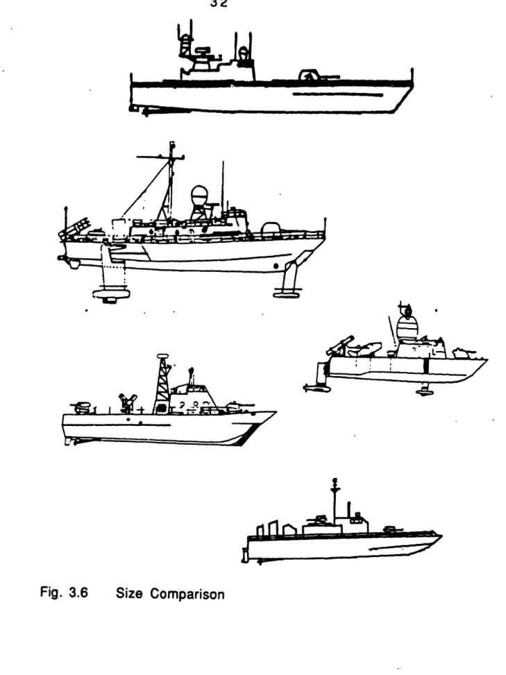
In figures 3.1 through ship are presented, in were const ructed and
3.5 the gross characteristics of each addition to the country for which the
their delivery period. Figure 3.6 presents the ships as t dry dock next to each other in a scale order for t he reader to gain an idea of t
their relative size.
hey could appear in ratio of 1/400, in heir appearance and
Figure 3.1
Country: USA(for South Korea) Builder: Tacoma Year delivered: 1977 Propulsion: L.O.A.: 99.9 FT Displacement: 72.5 Tons F.L. Speed: 45 Knots Complement: 11
(3) AVCO-LYCOMING Gas Turbines at 6000 SHP V-Drive and 3 CRP Propellers.
(2) Volvo Diesel Outdrives.
Weapons: (1) Twin Emerlec 30 mm
(2) Twin M60 Machine Guns (2) 40 mm Grenade Launchers
MK 93 G Fire Control System.
CPIC
-r
r r --
sk mh
-
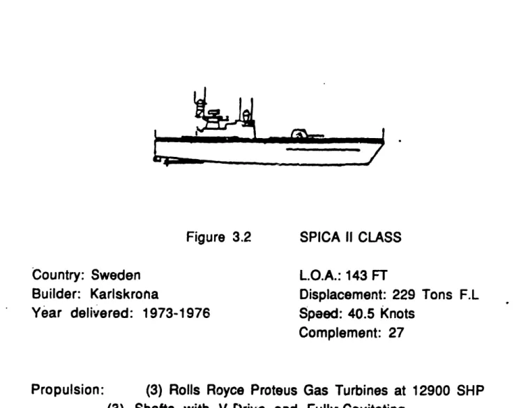
Figure 3.2 Country: Sweden Builder: Karlskrona Year delivered: 1973-1976 SPICA II CLASS L.O.A.: 143 FT Displacement: 229 Tons F.L Speed: 40.5 Knots Complement: 27
Propulsion: (3) Rolls Royce Proteus Gas Turbines at 12900 SHP (3) Shafts with VDrive and Fully-Cavitating
CPR Propellers.
Weapons: (8) RBS 15 SSM (Single launchers) (1) 57 mm L70 MK2 Boffors
(6) 21-Inch Torpedo tubes Mine Rails
(4) A/S Elma Grenade launchers (in some) Phillips 9LV 200 MK2 Fire Control System. Sensors:
1e,.
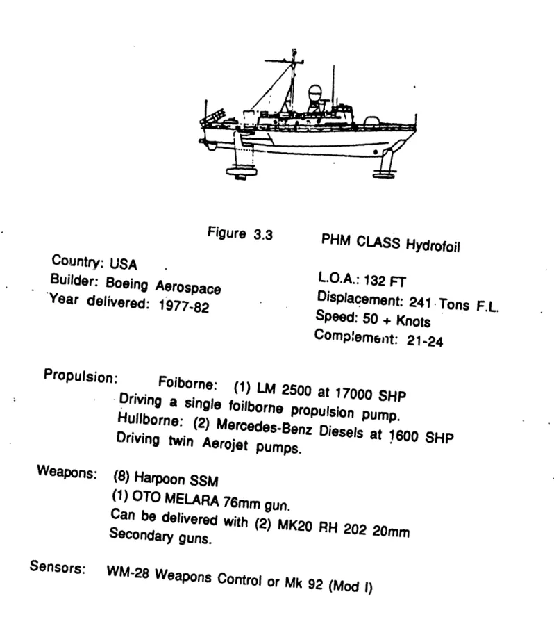
Figure 3.3 Country: USA
Builder: Boeing Aerospace 'Year delivered: 1977-82 PHM CLASS Hydrofoil L.O.A.: 132 FT Displacement: 241 Tons F.L. Speed: 50 + Knots Complemeit: 21-24 Propulsion: Foiborne: (1) LM 2500 at 17000 SHP
Driving a single foilborne
propulsion pump. Hullborne: (2) Mercedes-Benz Diesels at 1600 SHP Driving twin Aerojet pumps. Weapons: (8) Harpoon SSM (1) OTO MELARA 7 6mm gun. Can be delivered with
(2) MK20 RH 202 20mm
Secondary guns.
Sensors:
WM-28 Weapons Control or Mk
Figure3.4 Country: Israel
Builder: Israel Shipyards *Year delivered: 1983-85 Propulsion: M 161 CLASS Hydrofoil L.O.A.: 84 FT Displacement: 105 Tons F.L. Speed: 52 Knots
Complement: 3 min-15 max
Foilborne: (1) Allison 501-KF at 5400 SHP Z-Drive with supercavitating four bladed CCP
Hullborne: Twin Maritime Industries
retractable and steerable outdrives at 130 HP. Three bladed FP steel propellers.
Weapons: (4) Harpoon SSM
(2) IAI Gabriel MK III SSM (1) Twin Emerlec 30 mm ECCM/ESM Fire Control Radar.
Figure 3.5 Country: USA
Builder: Bell Halter Year delivered: Design ·
Propulsion:
APB 34 CLASS SES L.O.A.: 111.5 FT Displacement: 118 Tons F.L. ' Speed: 5 Knots Complement: 24 (2) MTU Diesels at 5500 SHP Weapons: (4) Exocet MK 39 SSM (1) Bofors 40 mm gun
(2) Emerlec 30 mm twin guns
(2) 50 Cal machine guns.
Phillips 9LV 200 MK2 Fire Control System.
i 1-6-
---Fig. 3.6 Size Comparison
and
CHAPTER 4
OVERALL ANALYSIS OF SHIPS
This chapter compares the overall design features of the ships. In order to start analyzing the ships, the design differences in full load weights, weight, volume, and deck space allocation fractions, as well as, the overall design
characteristics should be examined on a gross level.
Further in depth analysis of the results of this chapter will be presented in following chapters.
4
1_f .S..
5
B
RACIELEB
LST
LCS
The maj or charact er i st i cs of t he vessels are show n i n
table 4.1. The first two vessels are of the monohull design (the CPIC and the SPICA II). After the monohulls the two hydrofoil s, PHM and M161 are presented. The final vessel is the SES design (APB34). The ships' payload is presented in
t able 4.2.
4.1.1 The CPIC
This short ship, built by Tacoma shipyards for the South Korean Navy in 1977 is a short range, high speed
pat rol craft designed for coastal mi ssi ons. Its
sophisticated all-gun armament, shallow draft, and high
speed make CPIC ideally suited for "guerrilla" warfare
co :g ,
V- g)
a
(0w 'i co V 0 ~D :0 U; co u_ ID VE
a R a c IL ° cn C.) D, C6 cm CI N CI 0) v CY _rl CY O C) U) 0 0 . ._ 0-
. C0 M _- o Pj LO C) U) +(
W to0 0 Cl I. o4 U) t fl W) In 0 CO 0 -N 0 0 c00 -
_- _- r co W-cD C)00
_U V O O (D co r o CY 9- N -E .8 o .5i
x CD C)F .8 ' 0 0 ;a 0) O.. .) s.-I
C') C ILI 3=~ * a 3 S , _ e _ LL 4 U) 0 a < > >0 m CL C' le Cv, in .4 . 0 I.-cm C CI co cm LU -J 1mI--X3 oO m us =
Mr
00.
0 IV Cu C 0 m . -a X E m _ CoR n, m0 3I
C.>0
E U) I0 E EEEU
I- -. So E C E E 0 C E E C E E _ . Lo E E X o 0 0 C:3 CD N ui -J I-.a
0
-I Ip 0.4.1.2 The SPICA II
This is a Swedish ship built by Karls.krona Varnet
between 1973-76. The SPICA II differs in appearance from other ships of the similar type, as it has a small deckhouse set far aft. The ships of this design underwent major
modifications in 1984. SSM missile launchers were fitted
with new CIC modernized electronics and a new 57mm gun
and hull mounted sonar. These ships have been built and then modernized for surface and underwater surveillance in the restricted waters around Scandinavia.
4.1.3 The PHM origi mi ss the comp ships up to
The NATO Fast Patrol Ship
nated in mid-1969 to co
ile-armed Soviet Osa/Kom;
Medi t er r anean w at er s.
ileted
its acceptance
trial
of this design were built 1982. The PHM h. individual comt it can be adapte fisheries law resources. In tl navy will be pr
with fast carri
and amphibious ref uel I i ng Guided mi Dmbat t he ar type f as The first s on June by Boeing
as sufficient design flexibi
)at systems variations by ed for such roles as ant isu
enf orcement, and protect his study the design now a esented. PHM is capable of
er task groups, convoys of
assault groups, with the
ssile (NATO/ PHM) t hreat posed by t patrol boats in PHM, Pegasus, 1977. Five other Marine Systems,
lity to allow for
any country. Thus
bmarine warfare, ion of offshore
lctive in the U.S. crossing oceans f merchant ships aid of an at-sea
The M161 The Aerospace Two more Limited, in first M161, Corporation, M1 61 s have later years.
Shimrit, designed by Grumman
was launched in Florida in 1981. been built by Israel Shipyards,
The M161 is a very powerfully-armed strike vessel.
Its operation as a "day- boat" has had a significant
influence on the choice of the ship's syst ems and
arrangements. The M1 61 has been designed for a wide range
of military roles, and can be fitted with a variety of
weapons. Designs are available wit h dif feri ng payloads and
endurances for appl i cat i ons including gunboat, troop
transport, surveillance craft, missile boat, inshore ASW patrol, EEZ patrol and search and rescue.
4.1.5 The APB34 APB34 is a venture of Bel I services, Inc. design created by Aerospace Textron
Bell- Halt er,
and Halt er
a joint
Mari ne
APB34 design represents an improvement over the
successf ul SES- 1 00B design.
APB34 offers a greater speed for a given horsepower,
with better seakeeping and platform stability, particularly in high sea states. Its greater deck area enables awesome concentration of fire power capability, provided that the
desi gner can f i t t hem weight- w i se.
4,2C MEARLS_YIE GHTS
In order to be able to categorize all weight indices
t he navy w ei ght cl assi f i cat i on syst em Shi ps Work
Breakdown Structure (SWBS) is used (See Appendix A).
Further information about this system may be found in reference 21. The weight allocation fraction for each ship can be seen in figure 4.1 The weight breakdown for each
ship i n absol ute scale can be found i n figure 4.2.
4.2.1
4.2.1.1
Weight all ocat i on f ract i on
SWBS Group 100 (Hull st r uct ures)
The advantage of the Aluminum construction can be
easily seen, comparing the hull structure fraction. SPICA
II, an all Steel vessel, has 36 % of its overall weight dedicated to structure, leaving less weight fraction for other areas. The same advantage exists for the hydrof oils,
al t hough t hei r hul 1, must have addi t i onal' st rengt h t o resi st
wave impact and emergency landing in high seas at
foilborne speeds. The advantage of the Aluminum hull
cannot be seen in APB34 as the safety factors used in SES structural designs are larger than those of the monohulls. The SES design of our study needed large safety factors in order to provide a reasonable margin to account for
unknowns in the design process, due to the limited
experience from the SESs that are already at sea.
4.2.1.2 SWBS Group 200 (Propulsion plant)
The i ncorporat i on of the di esel s for -hullborne
up.
the
CPI
The t hree gas t urbi nes and t he V- dr i ve of t he CPIC have
same effect as above, although they make the small C a very fast craft.
4.2.1.3 SWBS Group 300 (Electric plant)
The group 300 wei ght f ract i on i s a di rect consequence of the payload each ship can carry. The M161 an extremely powerful vessel, has the biggest fraction as it is carrying two big generators to fulfill its payload requirements. The minimal discrete generator size of the CPIC, results in a
compar at i vel y hi gh el ect r i c plant w ei ght f ract i on.
4.2.1.4 SWBS Group 400 (Command and Surveillance)
M161 with a large radome on the deckhouse has the highest group 400 weight fraction. SPICA II comes next, having undergone major modifications lately, as Europeans
t end to emphasize command and surveillance more than the U.S. designers. Excluding the CPIC, the other two American designs have the similar group 400 weight fraction.
4.2.1.5 SWBS Group 500 (Auxiliary systems)
The two hydrofoils have the higher group 500 weight fraction, as they need very powerful hydraulic systems for
t he demands of t heir control systems, in both hull borne and
foilborne operation. The multiple levels of redundancy
needed to assure continued operation in the event of system failure, drive the auxiliary systems weight-up.
The M161 has a lower group 500 fraction than the PHM as it has to support a much smaller crew. fans are the major contributors to the increase auxiliary systems weight fraction in the APB34. S much larger than the CPIC, with a lengthier missi requirement to support a larger crew, has a
aux i I i ary syst ems w ei ght f ract i on.
4.2.1.6 t hat of
Lifting
of the PICA II on, and largerSWBS Group 600 (Out fit and f urni shi ngs)
CPIC, due to its size and its short mission, and M161, due to its very small area devoted to personnel, as well as, its short mission have the smaller group 600 weight
fraction. The M161 fraction is very small, as crew
comforts take second place in this ship. The other vessels have approximately the same outfit and furnishings weight fraction, with the more "spacious" European design SPICA II devot i ng a larger f ract i on t o t he group 600 wei ght s.
4.2.1 .7 SWBS Group 700 (Armament)
The variation from 3.6% to 15.2% is
i ndi cat or of combat i bi I i t y, since volume
systems is more important in some of the must be noted that the heavily loaded, for i
has t he bi gger ar mament w ei ght f ract i on
not a good
of weapon
ships. But it
4.2.1.8 Loads and margi ns f ract ion
When the Group 100- 700 weights are subtracted from
f ul I load di splacement t he remai ni ng wei ght s are t he I oads
and margins.
4.2.2 Absol ute Scale Weights
Figure 4.2 presents the distribution of the ship's
w eight s i n absol ut e scal e.
The group 1
larger than that approximately th happens to the gr to its large hydra weight. The weigl than that of the S
00 weight of SPI
of the PHM, al t
e same full load
)up 200 weight of t
lulic system has a
ht of t he loads car
PICA II.
CA II is significantly
hough the ships have weight. The opposite
he two ships. PHM, due
much bigger group 500
'ried by PHM is bigger
Comparing APB34 approximately the same
mention the group 100 reasons explained earlie
and M161, vessels w
full load displacement,
weight of the APB34
r in this chapter. hi c we , f 3V OLMECMPRLA I SON The di mission in the internal divided Appendi (Human ferent design
characteristic
allocation of volume devot by the Ship x B) in four ma support), V3philosophies, design trends, and s of each ship play a significant role volume around a navy vessel. The
:ed to different ship functions is
Space Classification System (See
jor groups: V1 (Mission support), V2 (Ship support), V4 (Ship mobility
h have
should or the
systems). The internal volume allocation for each vessel can be found in figure 4.3.
There is
volumes. If
measurement, errors, due to
4.3.1
always a problem with error when compari
even one excludes t he accuracy
volume measurements are still subject
t he overlay of t he f unct i onal areas i n a shi ng
of to
p.
Mission support (VI)
Mission area is driven by the mission and systems weight fraction. The larger the mission fraction the more significant the mission impact i
ship. combat support s on the For
mission
must be aust er it.fraction
t hat herweapons systems with the support fraction and the payl alike. M161 has the largest VI
y for living spaces. APB34
but a high payload weight f weapons are denser.
same density, the
oad weight fraction
fraction, due to its
has a smaller V1
raction. This means
Personnel Support (V2) Personnel manning requir have a greater
habitability, if
support ement s.fraction
manningis driven by human support and A "plush" habitability ship would than a ship designed for "austere"
w ere const ant .
SPICA II has the larger volume fraction allocated to
personnel, but at the same time a large personnel carrying capacity. M161 has a significantly lower personneL support
fraction, than the other vessels, as in this ship mission requirement s are enhanced instead.
4.3.3 Ship support (V3)
Shi p support and shi p mobi l i t y syst ems f ract i ons t ake
t he largest port i on of t he volume f ract i on. This f ract i on i s
al most const ant at 60% f or all t he shi ps st udi ed.
In all the ships the volume fraction dedicated to ship support is held constant around 35%, with the exception of PHM. This is due to the small redundant gas turbines used for power generation, as well as the 400 Hz frequency system used for electrical power, which is smaller and
I i ght er compared t o a comparable 60 Hz syst em.
4.3.4 Shi p mobi I i t y syst em (V4)
All the ships use Gas turbines for main propulsion with the exception of APB34. It is proven by various studies that if two boats with the same hull form have the same mobility system fraction, and the one uses diesels for main propulsors and the other gas. turbines, the one with the gas turbines will achieve a much higher speed. This is due to the lower volume specific ratio(volume vs
pow er avai I abl e) of t he gas t urbi nes.
The same f ract i on (approxi mat el y 20%) i s dedi cat ed t o V4 volume fraction to all the ships, with the exception of
PHM.
SPICA II, M161, and APB34 have a low fraction-of ship
M161 has two small retractable and steerable outdrives used for auxiliary propulsion, which do not affect the size of the engine roon. SPICA II has only three small Gas Turbines for boost and cruising speed, and and APB34 two
Diesels only. We should note here that there is always a trade- off between t he vol ume dedicated to ship support and
t he vol ume dedi cat ed t o shi p mobi I i t y syst em.
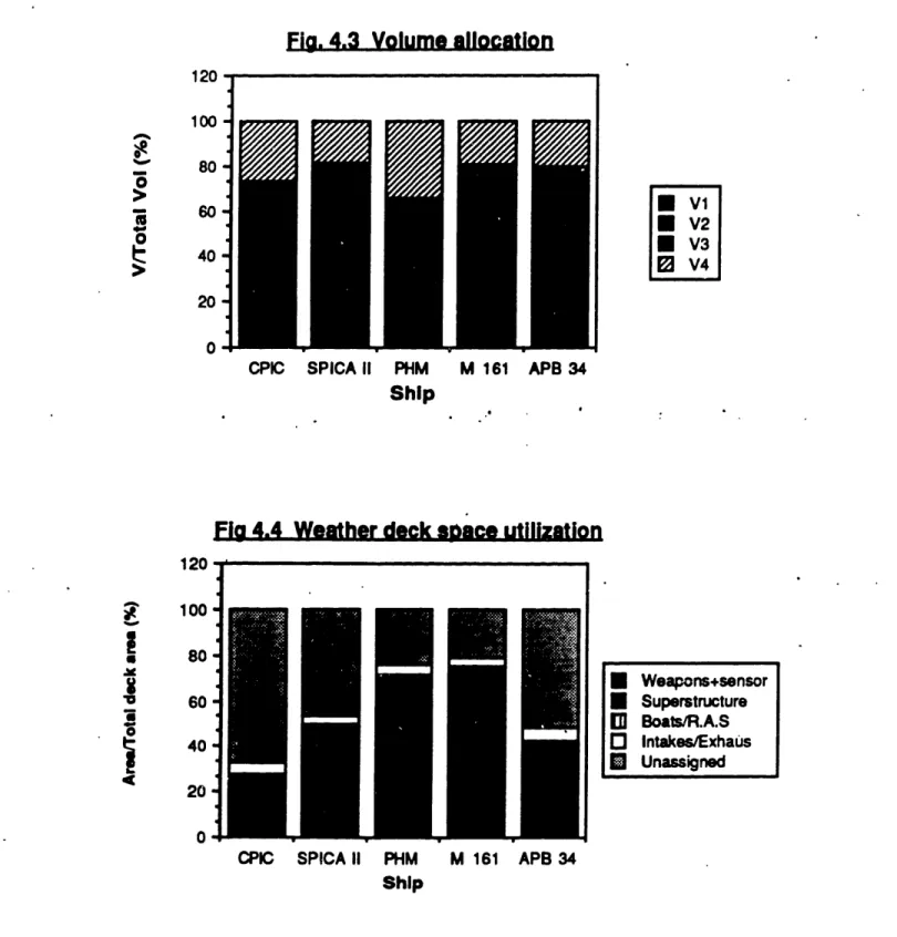
44 WEAIR-OECK. SPACEQMEARL U
Weapons, launchers, superstructure, exhausts and
intakes, small boats, and replenishment at sea equipment compete for available topside area. This occurs in al I naval ship designs and is especially critical in the very small area available on the combat ants of our study. It is in this aspect that the SES APB34 has a great advantage. An almost rectangle area of 111 x 39 ft 2, which allows for
great ar rangeabi I ity of weaponry and communication
systems. This in turn, provides for less probl ems
concerning weapons and elect romagnet ic compatibi I ity. The weat her deck space ut i lizat ion can be found i n figure 4.4.
4.4.1 Weapons/ Sensors f ract i on.
The smallest weapons/sensors fraction can be seen
for CPIC, due to small weapon systems. SPICA II has the highest at 42.70/4 due to the mine rails and large torpedo tubes. Although the weapons/sensors fraction is only 24% in the APB34 design, the actual area given to weapons and sensors is very large. It is merely shadowed by the except i onal ly I arge deck area.
Superst ruct ure f ract ion SPICA II of amidship significant ly especially in large CIC.
has a very small
s. The superstrL
higher in the
the PHM, with its
superstructure located
icture area fraction
hydrofoil designs,
large communications
Boats And Replenishment- At- Sea Fract ion
Small crews require few life rafts Therefore the boats fraction of the weat i nsi gni f i cant. Most of the ships have been
boat s", so t he repl eni shment at sea f ract i
There is no more than one replenishment
one of them.
in an emergency. her deck area is designed as "day on is very small. stations in each The t he PHM duration larger replenishment at as expected, due to its
(longer t an any cf t'he ot
sea fraction
long period her vessels).
appears in
of mission
4.4.4 I nt ake And Exhaust Fract i on
There is a association between the intake and exhaust fraction and the Shaft Horse Power per displacement for each ship. The higher the main propulsion ship-size ratio, the larger area fraction that is needed for intakes and exhausts. 4.4.2
aft
is
and and 4.4.31A. C
HAPIERCNCI.UMLQN.
The major design differences have been identified in this chapter. A conclusion common for all ships is that mission drives weapons systems enhancement, which usually requires more space. Speed needs more weight and space. With speed, range at high speed, and payload being the three most important factors, sacrifices must be made
elsewhere. The next chapter will try to explain how
different philosophies drive the certain designs, and where the sacrifices are made to enhance mission area. It will analyze the trends by ship size or mission inherent to the small combat ants of t his st udy.
Fi. 4.1 Weights fraction
II
CPIC SPICA II PHM
SHIP
M161 APB 34
Fig. 4.2 Full load weights
241 229 105 118 72.5 I I I I I I
CPIC M 161 APB 34 SPICA II PHM SHIP 120 0-. 0 C 10080 - 60-40 - 20- n-300 A 200 100 -0 I wi I W2 * W3 0 W4 O WS W6 * W7 E Loads+margin . I I I I I II
Fla. 4.3 Volume allocation
CPIC SPICA II PHM M 161 APB 34
Ship
Fig 4.4 Weather deck sbace utilization
CPIC SPICA II PHM M 161 APB 34
Ship 120 100 80 0 60 40 20 0 - VI V2 V3 ± V4 120
I
I
la 0 I 100 80 60 40 20 0 * Weapons+sensor * Superstructure al Boats/R.A.S O Intakes/Exhaus * UnassignedCHAPTER 5
DESIGN INDICES BY FUNCTIONAL AREA
In this chapter a furt chapter 4 are discussed. hydrofoil, SES) has its every design feature is afi of the country the vessel vessel, and t he mission for
her analysis of the findings of
Each different type (monohull,
own characteristics. Likewise,
fected by the design philosophy was built for, the size of the which the vessel was designed.
The
divided ar
f unct i onal areas e the following:
in which the vessels were
Mobi I it y
St r uct ure
Electrical power Payload
Command and Surveillance
Ship operat ions
Auxiliaries
Outfit and furnishings Personnel
A1-M. QMLLLIY
Even though effective modern missiles are capable of
being launched over-the-horizon, it is necessary to know
what is being targeted. To assure that missiles fired will
attack high-value units of an opposing force, it may be
necessary to close to relatively short range. Thus, tactics which take advantage of the speed and maneuverability of
the small Naval combatants are desirable. Speed and
maneuverability, along with endurance, seakeepi ng, and
flexibility of the various designs in the study are included under the title of mobility.
The issues of speed, range, seakeeping, and design
integration standards are analyzed in the following
paragraphs, in order to understand how each ,ile of them drives the philosophy in the design of the different ships.
5.1.1 Speed
The speed characteristics of the ships can be found in table 5.1.The fastest ship is M161, and the slowest SPICA II. In SPICA II greater emphasis is given to her
anti-submarine warfare role, especially after the maj or
modi f i cat i ons of 1 984. When on ant i - submar i ne oper at i ons,
SPICA II does not need to use all its speed, as the sonar
effectiveness becomes limited when operating above 25
Knots.
Small ships need to be fast as possible, in order to be
effective in their "guerrilla warfare" role, and to protect
themselves against any type of attack, as they lack
a. o O 0O I-.
amo
a) CY CM Z5 ! 00 /) ·- a3 10 It I Oc, 0r-
10 0D,+ c0 t
U) I o CD 0C I", I c CD C L Cv, NI. cv CD 0 CeD cli 1 L t 2 0c1 10i Ir O 'a0 0 Q) E 0 E, x co _ c m _ ~'Oa ca ou,
2
4-6 o -L
'-x c 4" C)I
O . _ 0 , CO C: 0 c: 0 L. °L °ewe2eV
E) -c o L cn Co 0o
t,, cm Ao' C) criYl C I a) c 0 17 ui C I" -l co =-Speed is affected by different design features. It can be written as a fraction of:
(Design Budget)x(Hydrodynami c Ef f i c.) Speed.
(Design St andard)
The desi gn budget i s a f unct i on of t he mai n propul si on weight fraction. The hydrodynamic efficiency is a function
of the Propulsive Coefficient and the Lift-to-drag ratio. Finally, the design standard is a function of the main
propulsion specific weight ratio.
From the above relation we can see that a
propulsive coefficient, and Lift to Drag rati'o are in of a speedy ship. Light propulsion components, as w powerful and light engines drive the speed of a vessel
5.1 .1 .1 large favor ell as up. Hydrodynami c Ef f i ci ency Hydrodynami c the production of propul si ve coef f i ci efficiency plays a speed, and it is
ent and t he lift t o dr
significant
a function ag ratio.
5.1 .1 .1a Propul si ve coef f i ci ent
The propulsive coefficient is the ratio between
power required to tow the ship at the designed speed,
Effective Horsepower, and the power measured in
shafting within the ship, the Shaft Horsepower. Thus i
the the the t is role in of the
act ually an i
interaction.
thus maximi
ndi cat or of t he ef f i ci ency of t he propulsor h
It is desired to have the largest possible zing the speed for a given Shaft Horsepower. The propulsive coefficient of all the ships is around 0.63 with the exception of the small CPIC and the PHM. PHM uses a single two stage waterjet as a foilborne propulsor,
which contributes to a reduction in propulsive coefficient
of about 20%. The reduction of the propulsive coefficient
of PHM is the trade-off to the reduction of the noise emitted by the propulsion system.
5.1.1.1b Lift to drag ratio.
Lift to drag ratio (L/D) is actually the ratio between the ship full load displacement and the ship's drag at the speed the ratio is calculated. For the hydrofoils the powered dynamic lift, and for the SESs the powered static
lift created by the foils or the lift system.
correspondingly, is 'added to the full load displacement,
making this ratio rise. Dynamic lift is created in the
pl ani ng craft at high speeds, thus raising t heir L/D rat io.
Hydrofoil craft
suffer practically
no wave making resistance when foilborne, and since the only *wetted surface is that of the foils and struts, they have alsofrictional resistance. As a result, for the same total
weight and power they can achieve speeds higher than the comparable high speed displacement or planing hulls. Before being foilborne, they experience drag both from
mai n hull and f rom t he foi I and st r uts, and have a "hump"
in the resistance curve, which is taken into consideration, as far as the take-off speed and installed horsepower are concerned.
lull PC,
A fundamental limitation is imposed here by the so called "square-cube" law, which impacts the growth potential of hydrofoil ships. Because the lift developed by the hydrofoil ships is proportional to their wing area (the
squar e of t he I i near di mensi on), i t f ol I ow s t hat as t he si ze
is increased the foils tend to outgrow the hull. The same problem exists in aircraft, but it is solved by increasing
speed and wing loading as size is increased. However
practical hydrofoil speeds are limited by cavitation.
up on and th
total
lower
n t he APB34, a SES, t he cushion of ai r rai ses the
the water, minimizing the contact between the e water. This results i n a subst ant ial decrease i n
resistance. As happens with the hydrofoil des drag permits higher speed for a given power.
ship
hul I
the ign,
The vertical accel erat i ons, resul t response of the SES to wave excitation, i mport ance, si nce t he t he rel at i ve mot i on b of the sidehulls and the water surface wil extent of air l eakage from the cushion.
motions will affect t he leakage below the s bow and stern. Whenever air leakage occurs sink deeper into the water, thereby resulti
ing from the
are of primary etween the keel
I determine the
Similarly, the
eals at both the the vessel will ng in increased drag of the immersed portions, that is, propulsive drag. In addition, the system must make up for some of this loss,
and hence there is additional power requirement associated with the lift fan operation for this case. There is a trade-off between the extent of immersion necessary to maintain the cushion and the result i ng propulsive drag from immersion, which manifests itself in the case of motion in waves, as wel as under stat i c perf ormance condit i ons.
CPIC has the lowest lift-to-drag ratio due--to its
Summarizing, the hydrodynamic efficiency of APB34 is
higher t han t he hydrodynamic ef fici ency of t he ot her shi ps.
The hydrofoils and SPICA II have approximately the same
product of L/ D and P.C.. The CPIC pays the penalty of its
size, having a hydrodynamic efficiency around 3.
5.1.1.2 Mai n Propul si on Weight Speci f i c Rat i o
The main propulsion weight specific ratio is a
measure of the overall weight to propulsion power efficiency of the propulsion plant. A lower ratio indicates
that the plant will provide more power for a given
propulsion plant weight, which may allow for an increase
in ship speed w i t hout an appreciable effect in
displacement, or may allow for a decrease in the physical size of the plant.
The small combatants of the study have advanced technology propulsion plants in order to save.weight. For
t his reason t he sm'all vessels having extremely lightweight
plants, have significantly lower W2/SHP ratio than other
bigger ships, which need more flexible and rugged
propulsion plants to fulfil their longer missions. The
weight saved in the plant allows higher speed and at the same time an increased proportion in the weight fractions of the other vital ship areas.
The sel ect i on of Di esels as propulsion engi nes for the
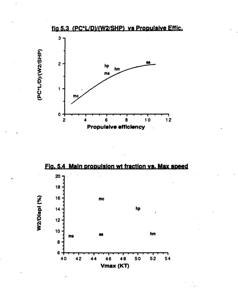
APB34 drives the main propulsion weight specific ratio up (see figures 5.1, and 5.2), since the diesels are heavier than gas turbines for the same delivered power. So, the effect of the large main propulsion weight specific ratio, of APB34 neutralizes the advantage of the high propulsive efficiency, making the ratio of the propulsive efficiency
over W2/SHP similar to that of the other ships, as can be
seen in figure 5.3.
PHM has a very low main propulsion weight specific
rat i o, necessitated by the trade-off of the lower
propulsive efficiency, due to its lower propulsi ve
coef f i ci ent . Thi s t rade- of f i s apparent i n t he ot her desi gns
as well, as can be seen from figure.5.3. Excluding the
inefficient smal I CPIC all the ot her ships have
approxi mat el y t he same rat i o of Propulsive Efficiency over
mai n propulsion weight speci f i c rat i o, living the
achi evement of a higher speed t o t he desi gn budget.
5.1.1.3 Design Budget
For a certain ship, t he higher design budget is i n favor
of a higher speed.
The design budget versus speed relation can be seen in
figure 5.4. The CPIC has the highest ratio due to its heavy transmission system for its size. Although PHM has only a Gas Turbine for propulsion and a light transmission, the water used for the foilborne or hullborne waterjets, and
the two diesels used for hullborne propulsion drive the
W2/ D rat i o up. The ot her three ships have a mai n propulsion
weight fract ion constant around 9.5.
5.1 .1.4 Conclusions
The discussion of t he previous paragraphs indicate t he high cost of CODOG plants and Diesel Propulsion. Due to the neutralization of high propulsive efficiencies from high main propulsion specific ratios, the most important indice,
as far as speed is concerned is the main propulsion weight
fraction. So speed costs, as we need a higher W2/ A to
Fia 5.1 Main DropUlsion wt spec. ratio vs. DispI 0 ' 4-3 SI mc hm ms hp 0 100 200 Dispi (TON) 300
Fig. 5.2 Main propulsion spe. wt vs. max speed
UN mw hm hp Vmax (KT) .0 -J 0. V) N Q.
-I
%Cw 5- 4- 3-ms 2 40 42 44 46 48 50 52 54 _ _ . . . , . . . . P A . . I . I . I . . . .fiag 5.3 (PC*L/D)/(W2/SHP) vs Propulsive Effic. 2- 1-0 2 hp Ms1 4 Jml hm 6 8 ' 10 12 Propulsive efficiency
Fig. 5.4 Main proDulsion wt fraction vs. Max speed
Za. 18 16 14 12 -10 8-6 40 mc hp ms ma _I m I _ I _ _* x ,,,,,, .I ... * 42 44 46 48 50 Vmax (KT) hm I. ' I 52 54 z S 0-a u, cu4 x 0 CI. a =1· U 0. %-v -30I.,
'a
I _ - I - I I ~ .... 3 I I5.1.2 Range
At sea all the ships run out of fuel before the stores
limit is reached. The ship with the longest endurance is
PHM, which with a replenishment at sea can extent its sailing days to limits reached from much larger
combat ants. With three under way refuelings PHM is
capable of crossing the Atlantic from Massachusetts to
United Kingdom at an average speed of 30 Knots in 4.2 days.
5.1.2.1
Stores endurance
PHM and CPIC, the two U.S. designs, are provided with stores' spaces that can suport the personnel for more than
a day (21/2 for CPIC and 5 for the PHM). Although no data
exist for SPICA II, after measuring its stores' spaces capacity, it is assured that she can be at sea for more than 4 days before her stores limits are reached.
5.1.2.2 Fuel endurance
Fuel endurance is a function coefficient, fuel weight, Specific
Ef f ect i ve Horse Power at endurance
of speed , propul
Fuel Consumption, speed.
Short missions characterize the small our study. These short missions are due to t
time at sea under the eye of the enemy. No
at maximum speed were found. This infor proprietary or is classified by the different
combat ant he need of data for r; mation is navi es. si ve and s of less ange kept
Accuracy i n t he endurance calculat ions of t he designs
can be found on Table 4.1 for a speed around 16 Knots. The
range of M161 at 16 knots could not be estimated, but is
seems t hat it is smaller than that appeari ng i n table 4.1 at 42 knots, due to the high SFC of the Gas Turbines in slow speeds, and the large drag as at the speed of 16 knots, as
at t hi s speed M161 is operat i ng hull borne.
Fuel endurance may be found from the following relationship:
(V)X(P.C.)X(WFUEL) 1
R- . -Cx(L/ D)x(WF/ D) x
(SFC) x(EHP) (SFC)
Where C i s a conversi on f act qr. So Range could be writt en as:
R( Desi gn Budget )x(Hydrodyn. Ef f i c.)x(Desi gn Ef f i c.)
The small L/D ratio of CPIC as well as its small size and its small installed SHP make its fuel 'endurance the.
smal I est of all t he ot her shi ps.
There is always a trade-off between payload weight and the weight of the fuel a vessel can carry (its design budget), and thus its range. For example the fuel weight, M161 can carry ranges from 16 to 21 tons, thus extending its range from 750 to 1150 Nm., depending on its mission
and the amount of crew aboard (4- 1 5).
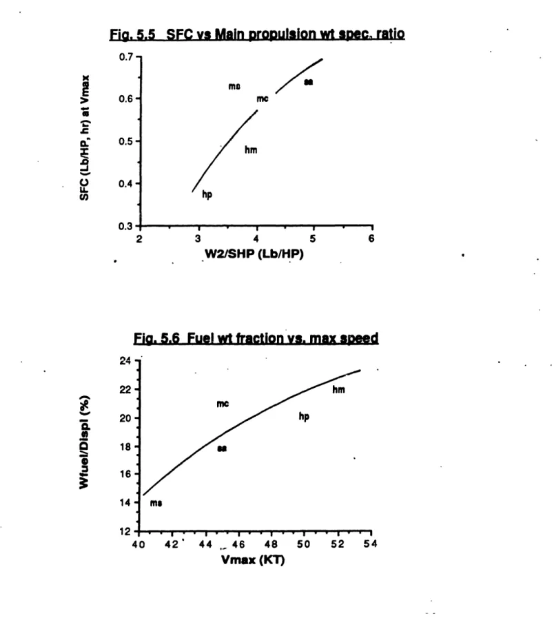
Ships with higher main propulsion weight specific ratios, tend to have higher SFCs at maximum speed, as can be seen from figure 5.5. This is due to the upward trend of
the Specific Fuel Consumption at maximum W2/SHPB is increased. There is also a mis concerning the fuel weight that can be carried ships. (See figure 5.6). The more speedy the higher t he f uel wei ght f ract i on.
speed sion tre
aboard t
ship, t
5.1.2.3 Concl usi ons
Design budget of fuel weight is the most important
met hod t o get a longer range. Range and mission I engt h are
cri t i cal to fuel cost. Efficient design standards and
hydrodynamic efficiency also play an important role.
Finally, it can be assumed that stores endurance does not normally limit the ships operation, as every ship reaches
the fuel limit first.
as nd he he
Fia. 5.5 SFC vs Main propulsion wt sPec. ratio m me 0.6- 0.5-0.4 -2 3 4 5 6 W2/SHP (Lb/HP)
Fig. 5.6 Fuel wt fraction vs. max speed
I I . Z4 22 -20 20 a 18- 16-14 12* 4 hm me hp u ms 0 42' 44, 46 48 Vmax (KT) 50 52 54 0.7-x
I
a -1 0lI. U, 0.3;·II . . . . l lip A, . . I I , I I5.1.3 Seakeepi ng
The seaworthiness of a hull form is related to three f actors: The wave response character i st i cs of t he shi p, the nature of the wave environment, and the ship's speed and
headi ng.
The limiting factors for heavy seas are military performance, crew performance, structural load limit and powering limit. Figure 5.7 shows this speed-wave envelope for a typical military vessel. It can be seen that ships
slow down first due to the degradation of military
effectiveness.ln the following pages the factors that
enhance ship performance and maneuverability in calm and heavy seas are i nt roduced.
For small combat ant s, t h
is the speed the ship can su severe slamming and deck
influence on t he seakeeping a
is its size as characterized I
the slenderness ratio (L/ V/3).
more is considered sufficient
II and CPIC have a slenderi
correspondingly. CPIC and SPI4
of about 400 to reduce pitch Vee aft to the transom of
slamming and heave.
a f i nal measure of seakeepi ng
stain in rough seas without
fetting. The greatest single
bility of a conventional ship
by its length, and especially
· A slenderness ratio of 7 or
to counter slamming. SPICA
ness ratios of 7.2 and 7.3
CA II use a deep Vee forward and heave. CPIC uses also a
Power Limit
30 (FT)
40
Speed wave height envelope.
1 _ 15 -co vn 10 2.5 S 10 20
Significant Wave Height "I
The use of the lifting surfaces on PHM and M1 61 reduces the effect of waves on these ships. The reaction of these
surface piercing hydrofoils to waves is substantially less
than for the high-speed displacement SPICA II or the
plani ng hull of CPIC. But t he requi rement f or shi p mot i on to
balance t he di st urbi ng forces caused by t he waves, coupl ed with geometric limits to a practical design, restricts the sea states in which high speed operation can be considered acceptable. For this reason, PHM and M161 augment their
stability by the mutual interworking of the submerged
foils with the ship's automatic control systems (ACS). The ACS provides continuous dynamic control of the ships during take-off, landing, and all foilborne operation. In
addition to providing the ship's roll and pitch stability, the
ACS controls the height above the water surface, causes banking in turns and eliminates ship motions caused by
orbital particle motion of the waves. The ship hull
operates above the effect of the surface waves. The foils that provide lift and control forces operate below the
water surface where wave effects diminish with depth.
Foilborne operations only become limited as the wave
heights exceed the hydrofoil strut length. The result is an
exceptionally smooth operating environment for crew and
combat syst ems equi pment. Less well real i zed i s t he maj or
contribution of the foil systems to motion reduction when hullborne. The foils act as dampers which significantly
reduce mot ions i n both t he roll and pitch modes.
Figure 5.8 shows the reduction of ships' speed as a function of the significant wave height. These data clearly show the ability of the hydrofoil ships to maintain speeds over 40 knots in rough seas.
5 p
I
0 cr en 1(3.3) 1 tt5.) . (FT)Significant Wave Height, M (FT)
Sea State
a .I8' Speed vs. Wave height