THE DEVELOPMENT OF AN ALTERNATIVE BUILDING SYSTEM BASED ON THE USE OF AN EXISTING STANDARDIZED COMPONENT:
PRECAST, PRESTRESSED, HOLLOW-CORE CONCRETE SLAB
by
LASZLO SIMOVIC
Bachelor of Architecture, Illinois Institute of Technology (1982)
SUBMITTED TO THE DEPARTMENT OF ARCHITECTURE IN PARTIAL FULFILLMENT FOR THE REQUIREMENTS
FOR THE DEGREE OF
MASTER OF SCIENCE IN ARCHITECTURE STUDIES
at the
MASSACHUSETTS INSTITUTE OF TECHNOLOGY June, 1984
©
Laszlo Simovic, 1984The author hereby grants to M.I.T. permission to reproduce and to distribute publicly copies of this thesis document in whole
or in pert. // - n Signature of Author
(i
-. aszlo Simovic epartment of Architecture May 11, 1984 Certified by ... ... -- . L - ; . * 3 -Waclaw Zalewski Professor of Structures Thesis Supervisor Accepted byN. John Habraken, Chairman Departmental Commitee for Graduate Students
MA 5SSACHiUS3ET TT'S INS~ITUTE
OF TECHNOLOGY
MITLibraies
Document Services
Room 14-0551 77 Massachusetts Avenue Cambridge, MA 02139 Ph: 617.253.2800 Email: [email protected] http://Iibraries.mit.edu/docsDISCLAIMER OF QUALITY
Due to the condition of the original material, there are unavoidable
flaws in this reproduction. We have made every effort possible to
provide you with the best copy available. If you are dissatisfied with
this product and find it unusable, please contact Document Services as
soon as possible.
Thank you.
The images contained in this document are of
the best quality available.
THE DEVELOPMENT OF AN ALTERNATIVE BUILDING SYSTEM BASED ON THE USE OF AN EXISTING STANDARDIZED COMPONENT:
PRECAST, PRESTRESSED, HOLLOW-CORE CONCRETE SLAB
by
LASZLO SIMOVIC Submitted to the Department of Massachusetts Institute of Technolog
in partial fulfillment of the requ Master of Science in Architecture
Architecture,
y, on May 11, 1984, irements for the
Studies degree.
ABSTRACT
The primary scope implementation for a
of this thesis is a conceptual new building systems approach. This system is based on a standardized,
and widely used prefabricated structural
economically component. feasible The type concrete in floor in question is a slab, extending it and roof decks to
precast, prestressed, hol low-core s use from its current application load-bearing wall panels.
The system incorporates three additional stuctural members in order to perform autonomously: continuous prefabricated reinforced concrete beams, high-strength steel bolts and prefabricated reinforced concrete support panels.
Its application, though primarily directed towards industry, can be utilized in the commercial and areas as well. Thesis Supervisor: Title: the housing industrial Waclaw Zalewski Professor of Structures design
In Commemoration To My Late Grandmother, Marija Simovic
ACKNOWLEDGEMENTS
First and foremost, I would like to attribute special thanks to my parents, Eva and Michael Simovic, for their love, constant concerns for my wel'l-being, and their financial support throughout my educational endeavors, and to my younger brother, Michael Jr., for his love and for taking care of my
father in my absence.
I wish to extend my sincere graditude to Marton Sass, an architect and close friend, who has influenced, guided and taught me everything I know in the architectural profession to date; ultimately broadening my perspective interests and goals. I would interests, perpetual l I wish to the idea great merr also i mora y shared
ke to thank Magda Sass, support, and for her with me. acknowledge Vaso of becomming an iments in sharing Bera, a c architect wonderful for h k i ndne lose friend, and to whom memories. er enduring ss she has who gave me I have had I would I for their through my I must ack Schmocker, to critica
ike to thank all friendship and graduate studies
my colleagues at M.I. constant source o in architecture.
nowledge a truly devoted
who "penetrated" my min Ily analyze my work with
professor at d, induced me a relentless T. and Harvard f inspiration l.l.T., Erdman to "think" and eye.
I wish to thank Reinhard Goethert alias "Shrimp" and humor in making the learning process "a piece for his assistance in organizing the contents of in a cohesive hierarchy.
Last but not the least, to Zalewski, who has shared and
ideas, and whose remarkable lasting impression on me.
for his wit
of cake" and my thoughts
my advisor, Professor inspired me with his br
mind has undoubtedly
Wac I aw il liant left a
TABLE OF CONTENTS
ABSTRACT. ... ii
ACKNOWLEDGEMENTS...iv
1.0 INTRODUCTION... 1.1 Standardized Prestressed Concrete Components 1.2 Manufacturers of Prestressed Concrete 1.3 Definition of Prestressed Concrete... Slabs.. 1 2 6 7 REQUIRED STRUCTURAL COMPONENTS. Prestressed ConcreteSlab... Prestressed Concrete Wall Panel Reinforced Concrete Beam... Reinforced Concrete Support Pan High-Strength Steel Bolts... DETAILED CONSIDERAT Foundation Details. Wall Details... Roof Details... Typical Sections... Optional Structural SEQUENCE Assembly Assembly IONS.. Detai .6 0 s OF ERECTION..-Method #1.... Method #2.... FINISHES... Interior... Exterior... DESIGN CONSIDERATIONS... Modules... Spans/Heights... Design Restrictions... Exterior Fennestrations... Applications... ECONOMICS OF SYSTEM... The Attributes of Precast, Economics of This System.. Prestressed ... Concrete. 8.0 EVALUATION & CONCLUSION... ... 102
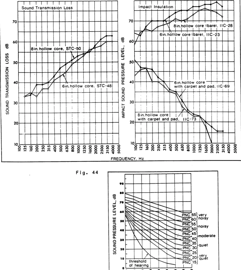
APPEND IX... Milestones of Prestressed Properties Peculiar to Pre Materials of Concrete... Tendons... Acoustical Properties... Thermal Properties... Concrete stressed 2.0 2.1 2.2 2.3 2.4 2.5 3.0 3.1 3.2 3.3 3.4 3.5 .10 .11 .11 .15 .18 .20 .23 .24 .29 .37 .41 .49 .54 .55 .61 .73 .74 .78 .84 .85 .86 .87 .87 .88 4 4 4 5 5 5 6 6 6 6 6 6 7 7 7 .0 .1 .2 .0 .1 .2 .0 .1 .2 .3 .4 .5 0 1 2 98 98 00 Co ... ... ... ... a ... 0 n cre t ... 0 ... 0 ... 0 ... 0 e. .. 04 05 09 11 15 18 27
-.
.
.
-.
.
.
-.
.
.
-.
.
.
.
.
.
.
.
.
.
.
.
l.
.
.
.
.
.
.
-.
.
.
.
.
.
1Fire Resistance...136 Coordination with Mechanical, Electrical and Other
Substems...140 Structural Fasteners... Bibliography...151
Since the 1950's, when prestressed concrete was introduced in the United States, its milieu had developed into what is now a widely acknowledged and accepted method of architectonical construction in the building industry. Its greatest asset is contributed to the economically feasible applications. Prestressed concrete's attributions have been virtually
limitless, encompassing projects in: residential, institutional, commercial and industrial applications. Its relevance to scale has been equally proven to be versatile and flexible.
1.1 STANDARD PRESTRESSED CONCRETE COMPONENTS
There are varieties of standardized prestressed concrete components that are mass produced in today's market. Each corresponding member pertains specific design applications along with apparent limitations. The following section presents an inventory of prestressed concrete components with brief overviews of prescribed applications and limitations. 1.1.1 Double Tees
Double tees are a basic floor and roof panel member with a span range of 80 feet. They are excellent for long cantilevers. Designed to simplify and speed erection of single and multi-story structures. Double tees create a unique effect when used vertically as exterior wall panels.
b-rn13L
1.1.2 Single Tees Single longer load i ng unit pr tees ar services canti lev architectees are used for floor and roof structural span ranging up to 120 feet, or for especia requirements. Normally 8, 10 and 12 feet w ovides large, and consequently quick, covera e popular for exposed ceilings, where
can be channeled between stems for easy ac ered, single tee ends can be custom s tural treatment. decks in Ily heavy ide, each ge. Single mechanical cess. When haped for
1.1.3 Hollow-Core Slabs
Hollow-core slabs find major application in residential, commercial, institutional and industrial structures where flat ceilings are desired. The bottom sides acts as the ceilings; the top side as the floor of the room above. Hollow-core slabs provide an effective barrier to airborne and impact sounds, and their voids can be used to carry mechanical services. They are generally designed for use in shorter spans up to 40 feet.
1.1.4 Channel Slabs Channel slabs
minimum deflecti floor and roof ranges.
provide a very rigid on characteristics. T
loads are encountered
structural member with hey are ideal where heavy in short and medium span
1.1.5 I-Beams
I-beams find application general ly as a long-span support extremely heavy loads. Available in spans feet, I-beams serve as the main girder beam-and-deck-systems. beam to to 100 in many rC 7HANNEL S LA E JS3S
1.1.6 Box Beams
Box beams are used primarily as girders In heavy-load type proper design, the large mechanical services.
in bridge construction, and also structural framing systems. With voids can accommodate various
1.1.7 Inverted T Beams
Inverted T beams and ledger beams reduce depth in a building because deck members can
ledges. They are generally used with double core slabs for structural framing.
tota I be su tees structural pported on and hollow
U.';
INVERTED T BEAMS AND LEDGER BEAMS1.1.8 Piles and Columns Piles are used as conditions exist. sections, in size piles are availab columns are integra system which makes
foundation supports They are available s from 10 to 24 inc le up to 54 inches I component of the rapid installation
where poor load-bearing in square or octagonal hes; hollow cylindrical in diameter. Precast precast column-beam-deck
1.1.9 Wall Panels
Wall panels are used for partial, f heights for either curtain wal Customized wall panels are availab textured or exposed aggregate units or color. They also may include
improved thermal characteristics.
ull-story, or multi-story I or load-bearing use. le in plain, sculptured, of almost any size, shape insulation materials for
1.2 MANUFACTURERS OF PRESTRESSED CONCRETE SLABS
There are a number of major manufacturers of prestressed hollow-core concrete slabs throughout the United States, each serving the same function. They are: Flexicore, Spancrete, Spiroll, Dynaspan, Dy-Core and Span Deck. Each manufacturer's product is distinguishable by the different shape of the voids at the center of the slabs, the standard widths in which they are manufactured and the configuration of the profiles.
?iGO.01
Flexicore (1'-4 & 2 -0) Spancrete (3'-4 & 5 -0)1.0 .0.0 .O.O.O0\
Spirolt (4'-0)0.(0.0.0.0.O.0.
Dynaspan (41-0 & 8'-0) Dy-Core (4'-0)1.3 DEFINITION OF PRESTRESSED CONCRETE
Prestressed concrete is an architectural and structural material of great strength. Prestressed architectural and structural concrete units are given predetermined, engineered stresses which counteract the stresses that occur when a unit
is subjected to loads. This is accomplished by combining two quality materials: high tensile steel strands and high strength concrete. There are two methods of prestressing high tensile steel strands: post-tensioning and pretensioning.
Post-tensioning prestressed concrete means that the steel is tensioned after the concrete Is placed and has gained a specific strength.
In pretensioning, high tensile steel strands are stretched between abutements at each end of the casting beds. Concrete is then machine extruded to encase the strands. As the concrete sets, it bonds to the tensioned steel. When the concrete reaches a specified strength, the tensioned strands are released from the abutements. This stresses the concrete, putting it under compression and creating built-in tensile strength.
Most commonly used prestressed concrete utilizes pretensioning due to its adaptibility to mass-production in a plant. This manufacturing operation takes place in an all-weather enclosed plants resulting in completely finished prefabricated members
for ready delivery to the job site. 1.3.1 Ordinary Concrete Beam
Even without a load, the ordinary concrete beam must carry its own considerable weight - which leaves only a portion of its
Under load, cracks.
the bottom of the beam will develop hairline
1.3.2 Prestressed Concrete Beam In a prestressed concrete beam, slight arch is noticeable. Energy action of the highly tensioned compression in the lower porti force is hereby created which in having to carry its own weight.
before it leaves the plant, a is stored in the unit by the steel which places a high on of the member. An upward effect relieves the beam of
The upward force along the length of the beam counteracts the load applied to the unit.
The fundamental idea of this thesis was initiated by friction connections -commonly associated with steel connections. It is used to service load transmission by friction through physical contact of adjoining surfaces of members after the bolts are pretensioned. (See fig. below). Friction-type connections offer a higher factor of safety against slip and thus is most
suitable when stress reversal or cyclical loading may occur.
Prestressed, hollow-core concrete today, is applied in a horizontal floor and roof decks. This thesis d prestressed concrete slabs from its context to a new and unconventional components, and non load-bearing wall
slabs, as acknowledged position, primarily for eals with extracting the notorious and existing one: load-bearing wall
pane Is. Chapter 2.0 deals with
slabs and its modif structural components building-system.
the descri ications,
required
ption of prestressed concrete along with the additional to a.chieve an autonomus
Chapter 3.0 concentrates on major deta connections by means of accomplishing the elements in question.
ils/solutions regarding structural integrity of
Chapter 4.0 explains the chronological sequence of assembly of the structural elements with two examples.
Chapter 5.0 addresses the selection of possible finishes for interior/exterior applications.
Chapter 6.0 explores accompanied with a typ Chapter 7.0 deals wi with comparisions in
systems.
Chapter 8.0, a on the anay Isis
i t
the design periphery of cal housing application. h the economical issues of relation to conventional conclusion and of prestressed this system this system construction
future research is drawn, based
The essential components of this system consists of five structural elements: prestressed hollow core concrete slabs, prestressed concrete wall panels, prefabricated reinforced concrete beams, prefabricated reinforced concrete support panels and high-strength steel bolts.
2.1 Prestressed Hollow-Core Concrete Slab
A typical cross-section of a prestressed concrete slab that is incorporated into either floor or roof decks is shown in Fig.
1. The holes or voids in the slabs are there to reduce unnecessary weight of the concrete at the neutral axis. There are number of thicknesses available pending on the span and the anticipated service loads. (Note the prestressed tendons at the bottom of the slab).
2.2 Prestressed Concrete Wall Panel
Prior to alterating the existing function of prestressed hollow core concrete slabs, three modifications are required to the standardized elements. See Fig. 1. They are: 1) the augmentation of prestressed tendons at the "top" of the slabs when the slabs are casted to secure symetrical forces in the prestressed tendons (to eliminate any unwarranted camber effects), 2) the elimination of two voids near both ends of
the slab compressi attached members permanent either be the manu
to create a -solid section to permi on forces (section where prefabricated
to member) and 3) holes that are drilled t (at the solid sections) to allow install
positioning of high-strength steel bolts. drilled at the job site or preferably pre-facturing plant. The diameter of the holes the types of
service loads.
bolts that will be incorporated p
t maxi beams hrough ation Holes dri I led depends ending mum is the and may at on on 2.2.1 Alterred Profile
There may be an optional alteration on the profile of the prestressed concrete elements shown in Fig. 2. This is to insure a weather-tight joint especially at the perimeter walls. And in doing so, the standard form (varies with manufacturers) of the concrete dispatch machine would have to be replaced to the new specification of the desired profile. The new form will cost a considerable amount, however, depending on the amount of members extruded, it could very likely off-set the initial investment. Also, the new profile would only be manufactured once.
2.2.2 Solid Prestressed Concrete Wall Panel There is a trade-off
panels are used versus concrete is required to
if solid prestressed concrete the hollow core concrete panels: carry virtual ly the same load (thi
wa II less nner
wall th because the wal I ickness), they can panels. (
and fewer prestressed tendons be idealily juxtapositioned in see Fig. 2). are required the center of Typical Voids Prestressed Tendons at Bottom
Only-PRESTRESSED CONCRETE FLOOR SLAB
Eliminate Voids When Casting.
Hole Pre-Drilled for Structural Steel Bolt
.I Optional for Added * S
.00.
Hole Support Prestressed Tendons at Top & Bottom(N
H_
Io
0
%
PRESTRESSED CONCRETE WALL PANEL
TYPICAL PRESTRESSED CONCRETE COMPONENTS
Fig. 1
r
I
Hole Pre-drilled for Structural Steel Bolt
.Prestressed Tendons at Top & Bottom
Cont. Neoprene Strip
PRESTRESSED CONCRETE WALL PANEL
Modified Profile
Prestressed Tendons Located Center of Panel
Hole Pre-drilled for Structural Steel Bolt
Cont. Neoprene S'
0
Ti
*
II
II
p
SOLID PRESTRESSED CONCRETE WALL PANEL
PRESTRESSED CONCRETE WALL PANELS Fig. 2
C;J
2.2.3 Exsiting Prestressed Concrete Wall Panels
Spancrete manufacturers have produced a prestressed concrete load-bearing wall panel system deriving from prestressed concrete slab production as shown below.
This system of panels ascertain exactly the same principal or concept of this thesis but it has one inherent restriction:
they are limited to one-story height intervals.
The decking system bears directly on top of the wall panels at
each floor Interval, with the proceeding wall panels
positioned on top of the decking system aligning directly over the preceding lower wall panels.
The connection is by exposed reinforcing bars in the joints that is grouted afterwards. This type of connection creates the problem of lateral rigidity after a certain height.
It is interesting to note the various profiles designed in the panels to meet certain conditions including an interlocking system, butt joints and a mitered corner condition.
MITERED CORNER A-Max. 45P
2.3 Reinforced Concrete Beam
A vital component of this system is beams (shown in Fig. 3) which functions:
the prefabricated concrete performs the following
1) Provides a temporary bracing for prestressed concrete wall panels at the initial stages of erection.
2) Aligns prestressed concrete wall panels when positioned in place.
3) Creates a ledge or bearing support for prestressed concrete floor slabs.
4) Increases overall lateral rigidity. The design parameters for the beams are:
1) The sizes of beams vary as a function of anticipated or prescribed service loads and the required surface area for the appropriate friction connection.
2) Holes are to be drilled through the beams to align with holes in the prestressed concrete wall panels and with countersinking provided for recessing boltheads and nuts in the concrete beams. (Grouted afterwards for waterproofing and to prevent loosening of the connection).
3) Concrete beams are to be continuous to correspond with the width of the total load-bearing wall length. (Beams may have to be segmented due to length restrictions in transportation).
4) The concrete beams may be designed in three structural mediums: reinforced concrete using ordinary rebars, high-strength concrete using prestressed high tensile steel strands, and post-tensioned concrete using high tensile steel cables applied and tensioned after beam is postioned in place. If the concrete beams are required to be segmented, and depending on the type of structural medium that is decided upon, there are four connections that are valid in order to achieve continuity of the beams, shown in Fig. 4. They are: bolt connection, welded connection with implanted steel anchors (not shown in dia.), connection with steel dowels and post-tensioning method as described above.
2.3.1 Steel Angle,
Steel angles may also be used to serve the same function the concrete beam (see Fig. 3). Listed below are some of advantages and disadvantages.
Advantages
Takes up less space. Readilt available.
Easily concealed for interior finishes.
Compatable with corrigated sheet metal and/or steel bar
as
joists for decking.
Elimination of follow-up grouting as in the case of concrete beams to conceal boltheads and nuts.
D i sadvantages
Needs Fireproofing.
-Hole Pre-drilled for Structural Steel Bol-t
STEEL ANGLE
Varies
Hole Pre-drilled for Structural Steel-
Bol-Countersinking for Grouting PREFABRICATED CONCRETE
TYPICAL CONTINUOUS STRUCTURAL BEAMS Fig. 3 U) ci) L Cu Varies
U
0
0
0
Corr i dor
/-Steel
DoweI---Reinforced Concrete Beam
Cori-idor Bolted
(--Support Panel Beyond4
Prestressed Concrete Beam
Corr i dor
4-Conc. Wa I
Beyond
-*I
Post-Tensioned Beam
CONNECTION OF PREFABRICATED REINFORCED CONCRETE BEAMS Fig. 4
Grouted Plugs for Bol ts
2.4 Reinforced Concrete Support Panel The re prefabr each s panel dependi panel s, accordi Fig. 5.
inforced concrete support panels are required to be icated according to specification requirements with pecific construction application. The height of the may vary according to floor heights, thickness may vary ng on the thickness of the prestressed concrete wall
and the ledge at the top of the panel may vary ng to the height and depth of the concrete beam. See
The sole function of the prefabricated reinforced concrete support panel is literally a support panel for the continuous concrete beams. It serves consecutively as a tentative and permanent support. It is also the termination member at either end of the prestressed concrete load-bearing wall system.
This component is very crutial especially during erection in t cranes to position and hold the bolted in place which may take
time. Also, this component initi and is the only member that requ onset of construction until the concrete wall panels and floor s
and grouted.
The reinforced concrete suppor perpendicular to the bearing wal is also stacked on top of each of and grouted for alignment.
Normal ly depending
in the economy of the system hat there is no waiting for concrete beams until they are up substancial and valuable ates the sequence of erection
ires temporary bracing at the first series of prestressed labs are positioned in place
t panel is positioned Is and the concrete beams. It her with steel dowels or pins
there are two, three or four support panels required on the length of the load-bearing walls.
Steel Dowel for Alignment & Placement of Upper
Panel-Hole for Temporary Bolting of Concrete Beam Width of Adjacent Prestressed Concrete Wa
I
Panels -0) 007
4-, 0 C a) 0. r-Width of Conc. Beam
-Width of Adjacent Prestressed Concrete
Wall Panels
-Width of Conc. Beam
Female Connection for Support Panel Below
2.5 High-Strength Steel Bolts
The final structural component; the key element that makes this building system autonomous, is the high-strength steel bolts. Its only function is to fasten the concrete beams to the prestressed concrete wall panels to create a friction-type connection.
Three types of bolts are applicable high-strength steel hexagon head bolts, hi interference-body bolts, and the Huckbolt, the Huck Bolt Company).
to this system: gh-strength steel
(manufactured by
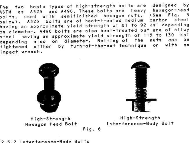
2.5.1 Hexagon Head Bolts
The two basic types of high-strength bolts are ASTM as A325 and A490. These bolts are heavy bolts, used with semifinished hexagon nuts. below). A325 bolts are of heat-treated medium having an approximate yield strength of 81 to 92 on diameter. A490 bolts are also heat-treated bu steel having an approximate yield strength of 1 depending also on diameter. Bolting of the tightened either by turn-of-the-nut technique impact wrench.
High-Strength Hexagon Head Bolt
Fig. 6 designed by hexagon-head (See Fig. 6 carbon steel ksi depending t are of alloy 15 to 130 ksi nuts can be or with an High-Strength Interference-Body Bolt 2.5.2 Interference-Body Bolts
bolts have a rounded head and raised ribs ons around the shank as well as parral lel to ual diameter of a given size of ribbed bolt i than the hole into which it is driven. (See F a ribbed bolt, the bolt actually cuts into the hole producing a relatively tight fit as mentioned above. The interference-body le in A325 and A490 characteristics.
that has the shank. s slightly ig. 6). In the edges and then bolt is These serrati The act larger driving around bo I ted avai lab
2.5.3 Huckbolt
The Huckbolt, also meeting ASTM Specifications of A325 and A490, are cut to exact final length required by its specific position in the design. One end of the bolt has a formed head; the other end is equiped with two concentric annular coarse and fine grooves, as shown in Fig. 7. The bolts are inserted through the designed holes which have been cased in both of the concrete beams and through the prestressed concrete wall panels. A metal lock colar is Inserted by hand over the bolt end and around the finer annular grooves. A specific hydralic machine tool then tightly clamps around the courser grooves at the end and stresses the bolt to approximately 70 per cent of its ultimate strength. Just before this point of stress is reached, the tool clamps around the collar, swaging this into position on the finer grooves, to hold the stress in the bolt. As soon as the swaging is done, the stress is increased slightly, to break off the bolt end at a deep grooved section formed in the bolt just in front of the swaged lock collar. Installation techniques are shown in Fig. 8.
oC ob0y1
Fig. 8
2.5.4 Washers
Washers are required for any of the bolts mentioned above. They should be oversized to assist transmission of compressive forces from the bolts to the concrete beams or steel angles. They should also have sufficient structural strength and applied on both the nut-side and bolt-side.
3.1 Foundation Details
Fig. 9 & 10 are detail connections of wall panels to the foundation wall. They both deal with direct bearing of prestressed concrete wall panels on top of poured-in-place concrete foundation walls with variations of exterior surfaces or finishes. The first detail is exposed concrete wall panels
and the second is with an added exterior cladding.
The latter two details (Fig. 11 & 12) involves bearing of wall panels dirrectly on top of the concrete footing, thereby eliminating costly formwork, labor and pouring of transported
concrete - a substantial savings both in time and labor.
Note: extra precautions should be taken when grouting joints of all wall members and thourough waterproofing particularly for basement applications.
V
Poured-in-Place Conc. Slab Weld Angle 2"x0'-4Cast into Panel
Cont. Weld Plates Anchored to Fndn Wall 3" Min 2" Rigid Insulation
r
\I-0 - Prestressed Concrete Wall Panels (Exposed)1" Grout, Shim & Caulk
Cont. #5 Rebars at Top & Bottom
(- Poured-in-Place Conc. Foundation Wall
TYPICAL CONNECTION OF WALL PANELS TO FOUNDATION WALL (Exposed Wall Panels)
Fig. 9 I
Poured-in-Place Conc. Slab
Weld Angle 2"xO'-4 Cast into Panel
Cont. Weld Plates Anchored to Fndn Wall
a;
2" Rigid Insulation
Prestressed Concrete Wall Panels
I'-
Exterior Cladding 1" Grout, Shim-& Caulk1" Max.
0
Grade
Cont. #5 Rebars at Top & Bottom
0 I
(- Poured-in-Place Conc. Foundation Wall
TYPICAL CONNECTION OF WALL PANELS TO FOUNDATION WALL (With Exterior Cladding)
Fig. 10 I
Poured-in-Place Conc. Slab
2" Rigid Insulation-,
-Cont. Groove in Footing Furnished to Li ne & Grade
Prestressed Concrete Wall Panel (Exposed)
Grade
Provide Waterproofing
Panels Shimmed & Grouted
3" Min.
Concrete Footing
TYPICAL CONNECTION OF WALL PANELS TO FOOTING (Slab-on-Grade)
Grouted Joint Concrete Topp (Optional) - - - m mi / / / d -Prestressed Concrete Floor Slab /
1~
. I 14-Exterior Cladding --- #3 Rebar Grouted into Keyways -High-Strength Steel Bolts Grouted FillCont. Concrete Beam
BASEMENT
Provide Waterproofing _---#3 Rebar Grouted into Keyways and/or Voids
in Panels
Cont. Groove in
Footing Furnished Panels Shimmed & Grouted to Line & Grade
--Concrete Footing
TYPICAL CONNECTION OF WALL PANELS TO FOOTING (With Basement)
3.2 Wall Details All of the prestressed floor slabs. fol lowing concrete
details are load-bearing connections of wall panels with prestressed concrete
first detail (Fig. 13) dea to five floor lengths) nuous concrete beams with
Is with continuous wall showing the connecti the floor slabs.
a detail showing a non-continuous This is where vertical continuity is Fig. 15 is a typical plumbing
stacks, water lines and other me intergrated feasibly and econom can be achieved without unnecessa slabs by simply eliminating p between the concrete beams.
The following four details (Fig. on exterior wall connections w alternative exterior and interior detail in Chapter 6.) chase detail chanical par ically withi ry drilling ortions of 16, 17, 18 & ith floor s finishes. ( wall panel achieved. shows how soil aphenalia can be n the system. It through the floor the wall panels
19) labs, Descr concentrates addressing ibed in more The (two conti Fig. 14 is connections. pane I s on of
1" Min. --- - m minim / 7 I-/ Prestressed Conc. Wall Panels Grouted Joint Prestressed Conc. Floor Slabs #3 Rebar Grouted into Keyways Concrete Topping (Optional) 1/8"x3" Hardboard Brg. Strip High-Strength Steel Bolts Grout Fill
Cont. Conc. Beam
SECTION A-A on Page 91
TYPICAL CONCRETE CONNECTION OF FLOOR SLABS TO LOAD-BEARING WALL PANELS (CONTINOUS)
m -own -/. Prestressed Conc. Wall Panels Grouted Joint Prestressed Conc. Floor Slabs #3 Rebar Grouted into Keyways Concrete Topping (Optional)
r.
m m 1/8"x3" Hardboard Brg. Strip H igh-Strength Steel Bolts Grout FillCont. Conc. Beam
SECTION A-A on Page9l
TYPICAL CONCRETE CONNECTION OF FLOOR SLABS TO LOAD-BEARING WALL PANELS (NON-CONTINUOUS)
SECTION B-B on Page9l TYPICAL PLUMBING CHASE
Fig. 15
Grouted Joint After Plumbing Installation -Concrete Topping
(Optional)
-Prestressed Conc. Floor Slabs
Space for Plumbing Chase
-Cont. Conc. Beam
(Prestressed Conc. Wall Panel Beyond
1" Min. Exposed Prestressed Conc. Wall Panels
SECT ION C-C on Page 91
TYPICAL CONCRETE CONNECTION OF FLOOR SLABS TO EXPOSED LOAD-BEARING WALL PANELS (CONTINUOUS)
m m
/
- - - 111'
Metal Studs with Batt Insul. Textured Plywood (Board on Batten, Beveled Siding, Tongue & Groove Planking, etc.)
-Cont. Conc. Beam Grout Filled
Metal Studs with Batt Insul.
-Stucco Finish
SECTION C-C on Page 91
OPTIONAL EXTERIOR FINISH (Wood, Stucco)
---
7---m - /
-Rigid Insul.
Face Brick
-Cont. Conc. Beam
Grout Filled
Concrete Block
-Rigid Insul.
SECTION C-C on Page 91
OPTIONAL EXTERIOR FINISH (Brick, Concrete Block)
Exposed Prestressed Conc. Wall Panels
Grout Filled
.Metal Studs With Batt Insul.
-Gypsum Board Finish
SECTION C-C on Page 91 OPTIONAL EXTERIOR FINISH
(Exposed Concrete) Fig. 19
3.3 Roof Details
The first detail (Fig. 20) shows a typical parapet condition with an alternative stone or sheet metal coping.
Fig. 21 is a typical roof detail.
The following detail (Fig. 22) shows a typical cantilevered roof.
Alt. Stone Coping
Sheet Metal Coping. Wood Blocking
3/8"x8" Anchor Bolt Grouted into Keyway
Wood Cant
Built-up Roofing over Rigid Insul.-1
Prestressed Conc. Roof Slabs 1/8"x3" Hardboard Brg. Strip 3" Min. Exterior Cladding Prestressed Conc. Wall Panels Rigid Insul. #3 Rebar Grouted into Keyways High-Strength Steel Bolts Grout Filled Cont. Conc. Beam
TYPICAL PARAPET WALL DETAIL Fig. 20
Built-up Roofing over Rigid Insul.
Sheet Metal Gravel Stop Wood Blocking 3/81"x8"1 Anchor Bolt Grouted into Keyway Rigid Insul. #3 Rebar Grouted into Keyways High-Strength Steel Bolts Grout Filled Cont. Conc. Beam
Exterior Cladding Prestressed Conc. Wall Panels
TYPICAL ROOF DETAIL Fig. 21
Sheet Metal Fascia-d High-Strength Steel Bolts Grout Filled Cont. Conc. Beam
- Exterior Cladding
- Prestressed Conc. Wall Panels
- #3 Rebar Grouted into Keyways
TYPICAL CANTILEVERED ROOF DETAIL Fig. 22
3.4 Typical Sections
The first detail (Fig. 23) prestressed concrete floor slabs wall panels, continuous concrete e levation.
The next detail concrete wall concrete floor
the floor slabs The
prest pane I
is a section through the with the prestressed concrete
beams and bolt connections in
(Fig. 24) is a section through the prestressed panels looking down towards the prestressed slabs and the continuous concrete beams below
(dotted line).
following detail (Fig. 25) is
ressed concrete wall panels and that supports the continuous con
a section through the at the concrete support crete beam.
Fig. 26 is a section through the prestressed concrete f slabs and the continuous concrete beams at the corr
looking towards the concrete support panel and at prestressed concrete wall panels.
Fig. 27 is a transverse section through the corr the prestressed concrete floor slabs, non prestressed concrete wall panels and the segmented concrete beam used for lateral support. Fig. show wa I I Fig. panel bu i I d idor showing load-bearing prefabricated
28 is also a transverse section through the corridor ng the prestressed concrete floor slabs, non load-bearing panels using typical concrete beam for lateral support.
29 is a section through the prestressed concrete and the concrete support panel at the exterior of ing. wa I I the I oor idor the i
Prestressed Concrete Wall Panels Beyond
Concrete Topping (Optional) #3 Rebar Grouted into KEYWAY prestressed Concrete Floor Slab Prestressed Tendons
lu..
QQ~rJOOQI
Cont. Concrete Beam
High-Strength Steel Bolts
SECTION D-D on Page 91
SECTION THROUGH FLOOR SLABS Fig. 23
1'
- - m-Grouted Vert. Keyw
Prestressed Conc. Wall Panel Prestressed Tendon Grouted Joint - F High-Strength - Steel Bolt
1
#3 Rebar Grouted nto KeywayK
ED
1" Min. Width of Conc. Beam (Below Slab)(-Prestressed Conc.
* Floor Slab
-DETAIL E on Page 91
SECTION THROUGH LOAD-BEARING WALL PANELS Fig. 24
o00oDoY.
D SECTION CORRIDOR LI I _ IV
I I I II
I
I
I
I
I Grouted Joint (-Prestressed Conc. Floor Slab-) Cont. Conc. (Below Slab) Prestressed Conc. Wall Panel (Non Load-Bearing))7
Conc. Support Panel Grouted Vert. Keyway Prestressed Conc. Wall Panel (Load-Bearing) Prestressed Tendon -Grouted Joint --- High-Strength Steel Bolt 1" Min. Width of Conc. Beam (Below Slab)(-Prestressed Conc. Floor Slab--k
-TAIL F on Page 91 '
THROUGH WALL PANELS AT CORRIDOR Fig. 25
I i I~ I
1"
Min. '~ i - S - ~ --- 7-/ m m I, / \ -- Prestressed Conc. Floor Slab Grouted Joint #3 Rebar Grouted into Keyway -Conc. Topping (*Optional) -- - m 1/8"x3" Hardboard Brg. StripCont. Conc. Beam
Prestressed Conc. Wall Panels Beyond Conc. Support Panel Beyond
SECTION G-G on Page 91
SECTION THROUGH FLOOR SLABS AT CORRIDOR F ig. 26
CORRIDOR
- Prestressed Conc. Wall Panel
- Conc. Topping (Optional) Prefab. Conc. Beam Bracing
(Resting on Top of Cont. Beam Beyond) Prestressed Conc. Floor Slab
.o.Q.&0000000 .
I
II
I
I
I
I
II
I
I
I
I
I ____A
' Butt Joint Prestressed Conc. Wall Panel Beyond Post-Tensioned TendonsCont. Conc. Beam Beyond
I
I
I
ISECTION H-H on Page 91
SECTION THROUGH FLOOR SLABS AT CORRIDOR (Optional Concrete Beam Bracing)
Fig. 27
]
II
_ _t-I
I
-I-
--1-I
1
I
I
I
I
I
ICORRIDOR
Prestressed Conc. WalI Panel
- Grouted Joint
- Conc. Topping (Optional) Prestressed Conc. Floor Slab
Post-Tensioned Tendons
0o0*000
Soo
iO
.Q00(o
0
Butt
Joint-Cont. Conc. Beam Beyond
Intermediary Conc. Beam Bracing High-Strength Steel Bolt
Prestressed Conc. Wall Panel Beyond
I
I
I
I
I
I
1 I
I
I
I
I
0 SECTION H-H on Page 91SECTION THROUGH FLOOR SLABS AT CORRIDOR (Optional Concrete Beam Bracing)
EXTERIOR
Optional Prestressed Conc. Wall Panel
(Non Load-Bearing)-7
Conc. Support Panel Grouted Vert. Keyway
- ---
.
Prestres Grouted High-Str Steel Bo 1" Min. Width of Beam (Be Prestres Floor Sl Cont. Co ---- T (Below S Prestres Wall Pan (Load-Be DETA IL J on Page 91SECTION THROUGH LOAD-BEARING WALL AT EXTERIOR WALL
Fig. 29 sed Tendon Joint ength it Conc. low Slab) sed Conc. Bb nc. lab) sed Conc. aring)
3.5 Optional Structural Members
Fig. 30
steel a
concrete
shows an alternative structural medium substituding ngles for the continuous prestressed reinforced
wall panels.
Fig. 31 shows the connection concrete paneIs using wide connection of the panels with
side. of non flange we I ded -conti beams stee I nuous prestressed as a guide and angles on either
Fig. 32 shows an exterior condition wall panels using structural T's and
of prestressed a steel plate.
concrete
The final detail (Fig. 33) shows an alternative prefabricated concrete beam.
2 1/2" Min.
7-li
.1
at... - -Prestressed Conc. Wall Panel Grouted Joint #3 Rebar Grou into Keyway Prestressed C Floor Slab Concrete Topp (Optional) ted onc. ingSECTION A-A on Page9l
TYPICAL STEEL CONNECTION OF FLOOR SLABS TO LOAD-BEARING WALL PANELS (CONT.)
Fig. 30
High-Strength Steel Bolts
1/8"x3" Hardboard Brg. Strip
2 1/2" Min. -/ I /
-{-Prestressed Conc. Wall Panel Grouted Joint #3 Rebar Grouted into Keyway Prestressed Conc. Floor Slab -Concrete Topping (Optional) - 1/8"tx3" Hardboard Brg. Strip- Cont. Steel Angle Welded to Wide Flange
Cont. Steel Wide Flange
NOTE: Provide Holes for Rebars
SECTION A-A on Page 91
TYPICAL STEEL CONNECTION OF FLOOR SLABS TO LOAD-BEARING WALL PANELS (NON-CONT.)
Fig. 31
-Prestressed Conc. Wall Panel Prestressed Conc Floor Slab #3 Rebar Grouted into Keyway 2 1/2" Min. Conc. Topping (Optional) -0 Grouted Joint 1/8"1x3" Hardboard Brg. Strip Cont. Steel T with Welded Webs
'-I
U
Elm
SECTION C-C on Page9l TYPICAL STEEL CONNECTION OF FLOOR SLABS
WALL PANELS (CONT.) WITH EXTERIOR Fig. 32 TO LOAD-BEARING CLADDING 4F Exterior Cladding Sq. Steel Plate High-Strength Steel Bolts
Prestressed Conc Floor Slab " min. Conc. Topping (Optional)--- 7-m umin~ -p 1~ / -'I_ Grouted Joint 1/8"x3" Ha Brg. Strip Exterior Cladding Prestressed Conc. Wall Panel High7Strength Steel Bolts
Cont. Conc. Beam
#3 Rebar Grouted into Keyway
SECT ION C-C on Page 91
TYPICAL CONCRETE CONNECTION OF FLOOR SLABS TO LOAD-BEARING WALL PANELS (CONT.) WITH EXTERIOR CLADDING
There are two methods of assembling the components of which one is more econom descriptions of assembly procedures will with the initial development.
prestressed cally feasib be described concrete le. Both starting
For both cases, The assumptions is that the foundation walls, or the footings of the foundation (two options of support for the prestressed concrete wall panels) have been casted and have reached sufficient strength to proceed the sequential erection process of construction.
4.1 Assembly Method #1
This method - the initial development
-concept at a rudimentary basis. The method a drawbacks which resulted in revamping the and with an additonal structural member concrete support wall. This is described in second method of assemby.
is appling the pparently had some order of erection
, a prefabricted
more detail in the
There are four procedures or steps that completes a cycle or one floor height.
Step 1
The setting of prestressed concrete wall panels length of one story high (for quick, easy bracing) on top of the foundation walIs and staggered format. Temporary bracing is requi member. preferab hand Ii ng grouted red for y at and n a each i l i
Step 2
Lifting of prefabricated concrete beams on either side of the prestressed concrete wall panels and held in place until high-strength steel bolts are positioned and bolted. Procedure
is the same for each load bearing wall. Note: two cranes are required simultaneously.
STEP 3
Placing of the prestressed concrete floor slabs. steel bars are positioned between every keyway a Temporary bracing may be removed after grout has subsequent yield strength.
Reinforcing nd grouted. reached its
Step 4
Positioning of corresponding prestressed concrete wall panels, also in a staggered format to infill initial voids developed at ground level and to give additional support. Height may vary according to desired lengths (limitations only to conventional transportation restrictions though additional
temporary bracing may be required if members are too high). Note: the bolts of the adjacent prestressed concrete wal I
panels may have to be loosened to allow wall panels to slide between concrete beams. Grouting may proceed at ground level between vertical keyways.
Step 5
Step 6
Same as step 3
Step 7
Step 8
Placement of prestressed concrete
load-bearing) that are slipped through spacings between prestressed concrete fl sheer wall for lateral rigidity. Grout al Note: sheer wall is conviently located central corridor.
wall panels (non continous slots or oor slabs to create a
I vertical keyways. on adjacent sides of
Step ~9
Step 10
4.2 Assembly Method #2
This is the subsequent method preceeding assembly method. are: an additional structural concrete support panels) and of erection.
due to some imperfections of the The difference between the two member (prefabricated continuous a switch in the sequencial steps
Step 1
The prefabricated concrete support panels are placed on top of the foundation walls, grouted and temporarily braced. The panels are placed perpendicular to the forthcomming load-bearing panels, at both ends of the anticipated load-bearing walIs and at the shear walIs as shown.
Note: there is a substancial reduction of bracings in this procedure.
Step 2
The prefabricated concrete beam i ledges on one side only of the exception of end walls), and bolted the panels.
Note: two cranes are not required time by having the support panel beams and eliminating valuable ti beams by the crane as in the first
s
s
hoisted on the upport panels (
through the beams
desi w i th
and and there is a savings s supporting the conc me consumed by holding assembly method. gned the into in rete the Step 3
The placement of prestressed concrete wall panels in a sequencial order on top of the foundation walls (or footings) and grouted. The concrete beam acts as a temporary support for the panels and eventually a permanent connection. The lengths of the panels may be of longer lengths and should vary in one story increments that are staggered at the top ends of the panels to add support and rigidity when construction continues
in height at the following stages of erection.
Note: No need of staggaring the prestressed concrete wall panels, and panels are of longer lengths.
Step 4
The corresponding concrete beam is placed on the opposite side of the prestressed concrete wall panels and onto the ledges of
the support panels.
The bolting procedures may proceed in a sequential order throughout the length of the load-bearing walIs.
Step5
bars are inserted between every keyway and grouted. Concrete beam is introduced to give lateral support.
These are the five procedures or steps that completes a cycle or one floor height.
Step 6
Same as step 2 and 4 Step 7
Same as step 5 with the additional step of placing the prestressed concrete wall panels (non load-bearing) on either side of the central corridor which acts as a shear wall as in the previous assembly procedure.
Step 8
Same as step 2 and 4 Step 9
Placing of the next series of prestressed concrete wall panels between the staggered ends of the panels below, and step 4. Step 10
-~ 'N
I
-'N K PROCEDURES OF ASSEMBLY Step OneA
A A
Step Two
0) C 0 -~ .C-'U C 0
Step Four
0 L L Go E (D L U) C/) L o0 00 .0 C,
A
Step Six
Step Seven
Conc. Floor Slabs & Non Load-Bearing Conc.
Step Eight
06 E co 0 CL a'-(U 0 0
Step Ten
5.1 INTERIOR FINISHES
5.1.1 Floors
Floor systems of prestressed concrete slabs readily themselves to virtually any
types of finishes may requ gypsum concrete or concrete, to the prestressed concrete of surface leveling. Under required when a resilient prestressed concrete slabs before application of any und
lend available floor finishes. Some ire an underlayment of mastic, while others are applied directly slabs with only a minimum amount
layment or concrete topping is floor covering is used. The should be thouroughly cleaned erlayment or concrete topping. Condition of the top surface of the installed deck will depending on span, load, openings and other details.
vary
When a concrete topping is desired, it can be designed to act structurally with the prestressed concrete slab as a composite system, or it can be assumed to act only as a fill material. This choice will affect the specification of the topping material and placement.
5.1.2 Concrete Finishes
When concrete is to be used structurally or as a wearing surface, one should specify a minimum of 3000 psi. Color pigments, hardeners or wearing aids may be added. Similar details should prevail for cast-in-place terrazzo. Where practical, align joints with the prestressed concrete slab joints.
1 1/2" Min. Conc. Topp i ng
Prestressed C Floor Slab
5.1.3 Floor Coverings on Underlayment Underlayment mate of the following concrete, mastic should be only irregularities.
rial should be speci general types: asp underlayment. Thi enough to
fied similar to the one haltic concrete, latex ckness of underlayment level off construction
imi tar
oor i ng
lacing,
specifications and procedures should be materials which normally require a mortar such as cut stone or precast terrazzo.
used bed
for for
Asphalt or Vinyl Tile or Sheet Floor Covering Underlayment - Fin. Level
Prestressed Conc. Floor Slab
5.1.4 Carpeting
For carpeting directly on prestressed concrete slabs, a coat of mastic leveling should be applied where irregula exceed 3/16 in. A minimum of 55 oz. pad should be specif
sk i m
r ities
ied.
Carpeting over Pad
Prestressed Conc. Floor Slab
S f p
5.1.5 Exposed Ceiling Slab - Painted
The prestressed concrete slabs have an exceptional ly smooth underside surface, obtained because of the thourough vibration of the dense concrete in steel forms in the casting beds. Nicely rounded corners are built into the individual units. When a paneled ceiling is desired in residential, commerc
school, hospital or similar applications, simply caulking joints between the slabs and painting is the most econom solution.
ia I, the ica I
The prime coat should be rubber latex paint sealer as is desirable for any other concrete coat may be rubber, oil paint, flat wal emulsified finish. A distintive appearance
stippling the final coat.
or a waterproof slab. The finish finish or an is obtained by
5.1.6 Other Ceiling Treatment Although the most economical caulking and painting as outl can be applied which produces
ceilings are obtained ined above, additional a variety of results.
by simply treatments
Cei I ing concrete
tiles that are applied directly onto the prestressed slabs. Spray app required, sprayed d finished. lied acoustical mineral fiber irectly on the
material when acoustical control is or other acoustical material may be slab's surface creating a textured
5.1.7 Suspended Ceiling
All conventional hung ceilings may be in prestressed concrete slabs by inserting joints between slabs before grouting.
conjunction the hangers with the in the Alternative I grouted, by the hangers y, ceilings may drilling underside in the cores. also be hung of the cores after and then slabs are inserting Hangers dril ling
may also be installed from the top of the through the cores, provided topping will be
Principal purpose of the suspended ceiling is to conceal ducts, pipes or other mechanical parapenalias.
slab used.
by
Galv. Strap Hanger Installed Before Slabs are Grouted
essed Conc. Slab
5.2 EXTERIOR CLADDING
There are a number of possible materials that can be directly to the facade of the exterior prestressed wall panels, bearing directly on the continuous beams. Of course one may simply choose to leave
panels exposed which also presents a wide variety of and textures. applied concrete concrete the wall finishes 5.2.1 Brick/Block
Brick and/or concrete block is compatable with this system. Its construction methodology is similar to brick veneer construction. See Fig. 34. The only difference is that scaffolding is required around the perifery of the building when laying the brick/block on the facade.
5.2.2 Wood/Stucco
Wood and/or stucco finish is another compatible alternative, and is also applied similarly to brick veneer construction. See Fig. 35.
5.2.3 Exposed Concrete
Exposed concrete provides the most flexibil textures, finishes and color variations. The applied in most cases when the prestressed panels are manufactured - a cost reduction. The interior side of the prestressed
need some sort of insulation: rigid 36 shows metal studs with batt insu
finish.
ity as far as finishes can be concrete wal I
concrete wall panel or batt insulation. lation and a gypsum
s wil I
Fig. board
A unique exterior finish can be achieved with a patented Corewall process. A revolving roller screeds and compacts the concrete on the top surface of the panels to create the desired architectural effect (see Fig.37). By varying the profile and spacing of a number of discs attached to the roller, a wide variety of sculptured finishes is available. Fig. 38 gives us a
achieved by various
sampling of exterior finishes that can be means.
Rigid Insul.
Face Brick
-Cont. Conc. Beam
*Grout Filled
Concrete Block
-Rigid Insul.
SECTION C-C on Page 91
OPTIONAL EXTERIOR FINISH (Brick, Concrete Block)
m
/
Metal Studs with Batt Insul. Textured Plywood
(Board on Batten, Beveled Siding, Tongue & Groove Planking, etc.)
*Cont. Conc. Beam Grout Filled
Metal Studs with Batt Insul.
Stucco Finish
SECTION C-C on Page 91
OPTIONAL EXTERIOR FINISH (Wood, Stucco)
-Exposed Prestressed Conc. Wall Panels
Grout Filled
.Metal Studs With Batt Insul.
-Gypsum Board Finish
SECTION C-C on Page 91 OPTIONAL EXTERIOR FINISH
(Exposed Concrete) Fig. 36
m Ca ~tJ -4 V F
~m
ii
~0 it,. rtznninnita"amn act 1 et~r 1 ur rw!rWill-.'
*~mrrnr:rw::
cv
r~sjcrkrrcmuch~iaM ~tA'.' *,
"itExposed Aggregat Exposa AggregCOl - RIDDOO
6.1 Modules
Among the prestressed concrete manufacturers mention previously in the introduction, there are alternate width dimensions of hollow-core concrete slabs that varies with each producer. The scope of dimensions are: 1'-4, 2'-0, 3'-4, 4'-O, 5'-0 and 8'-0 widths.
Based on these dimensions, the designer will need to know the nearest location where prestressed concrete members are produced and acknowledge the standard width dimensions associated with the manufacturer. This should serve as the basis for the module system of prestressed concrete hollow-core members incorporated into the design. In large metropolitian areas, there may be two or three manufacturers within a relative close proximity which presents the designer with a more flexible module selection.
Needless to say, the determination of module sizes plays an important role regarding two major criterias: economy, and design flexiblity. The larger the width dimension, i.e. larger member, the more economical it becomes simply on the basis of less labor requirements and quicker erection with fewer members. The design flexibility of the project also depends on the module dimensions because of the imposition of integration into the design in order to be efficient, economical, and functional.
The ideal module dimension 8'-0 and/or possible comb Both of these sizes are construction industry. of prestressed concrete nations of 4'-0 widths an architectonic dimens ( elements is if needbe). on in the
The modules should be aligned both horizontal ly and vertical ly i.e. the wall panels should correspond to the floor slabs. This should prevent any unneccessary cutting of elements. More important, is the allocation of reinforcing bars that is placed in keyways at ends of the prestressed concrete slabs to the adjoining floor slabs or wall panels (if exterior walls). In order to accomplish this, the floor slabs and the wal I panels have to align to allow rebars to penetrate through the wal I panels.
![Fig. 27]II _ _t-I I-I- --1-I 1I II II I](https://thumb-eu.123doks.com/thumbv2/123doknet/14733138.573505/53.918.122.787.345.894/fig-ii-i-i-i-i-ii-ii.webp)