Publisher’s version / Version de l'éditeur:
Cold Regions Science and Technology, 10, pp. 11-17, 1984
READ THESE TERMS AND CONDITIONS CAREFULLY BEFORE USING THIS WEBSITE. https://nrc-publications.canada.ca/eng/copyright
Vous avez des questions? Nous pouvons vous aider. Pour communiquer directement avec un auteur, consultez la première page de la revue dans laquelle son article a été publié afin de trouver ses coordonnées. Si vous n’arrivez pas à les repérer, communiquez avec nous à [email protected].
Questions? Contact the NRC Publications Archive team at
[email protected]. If you wish to email the authors directly, please see the first page of the publication for their contact information.
NRC Publications Archive
Archives des publications du CNRC
This publication could be one of several versions: author’s original, accepted manuscript or the publisher’s version. / La version de cette publication peut être l’une des suivantes : la version prépublication de l’auteur, la version acceptée du manuscrit ou la version de l’éditeur.
Access and use of this website and the material on it are subject to the Terms and Conditions set forth at
Grounded rubble fields adjacent to offshore structures
Sayed, M.; Frederking, R. M. W.
https://publications-cnrc.canada.ca/fra/droits
L’accès à ce site Web et l’utilisation de son contenu sont assujettis aux conditions présentées dans le site LISEZ CES CONDITIONS ATTENTIVEMENT AVANT D’UTILISER CE SITE WEB.
NRC Publications Record / Notice d'Archives des publications de CNRC:
https://nrc-publications.canada.ca/eng/view/object/?id=7fa743b0-552e-435d-b871-c45c8993ef02 https://publications-cnrc.canada.ca/fra/voir/objet/?id=7fa743b0-552e-435d-b871-c45c8993ef02Ser
THI
c . 2
B r n
II
#
National Research
Conseil national
Council Canada
de recherches Canada
GROUNDED RUBBLE FIELDS ADJACENT TO OFFSHORE STRUCTURES
by M. Sayed and R.M.W. Frederking
Reprinted from
Cold Regions Science and Technology Vol. 10 (19841, p. 11 - 17
DBR Paper No. 1250
Division of Building Research
Un modele c o n t i n u d e champs d'amas d e g l a c e r e p o s a n t s u r l e fond e s t 6labor'e. Dans c e modsle, l ' e n s e m b l e d e s b l o c s d e g l a c e e s t t r a i t ' e comme un mat'eriau d e Mohr-Coulomb e n 6 q u i l i b r e c r i t i q u e e t l a nappe de g l a c e e n v i r o n n a n t e c o n s t i t u e une f r o n t i s r e r i g i . d e . On o b t i e n t l a d i s t r i b u t l o n a p p r o x i m a t i v e d e s c o n t r a i n t e s 2 p a r t i r d e l a m6thode d e s r e l a t i o n s i n t ' e g r a l e s . Les c h a r g e s s u r un ouvrage c o n s t r u i t a u l a r g e d e s c S t e s e t a d j a c e n t a u champs d'amas d e g l a c e , s o n t exprimges e n f o n c t i o n d e s c o n t r a i n t e s maximales e x e r c g e s p a r l a nappe de g l a c e f l o t t a n t e . Les a u t e u r s examinent l ' i n f l u e n c e d e l a g g o m g t r i e du champ, d e l a r 6 s i s t a n c e
2
l f 6 c h o u a g e e t d e s p r o p r i G t 6 s d e s amas de g l a c e .Cold Regions Science and Technology, 10 ( 1984) 1 1 - 1 7
Elsevier Science Publishers B.V., Amsterdam - Printed in The Netherlands
GROUNDED RUBBLE FIELDS ADJACENT TO OFFSHORE STRUCTURES
M.Sayed and
R.M.W. Frederking
Geotechnical Section, Division of Building Research, National Research Council of Canada, Ottawa, Ontario K I A OR6 (Canada)
(Received September 26, 1983; accepted in revised form February 3, 1 9 8 4 )
ABSTRACT
A continuum model of grounded ice rubble fields is developed in which bulk rubble is treated as a Mohr-Coulomb material at critical equilibrium. The surrounding ice sheet is considered to form a rigid boundary. Approximate stress distributions are ob- tained using the method o f integral relations. Loads on an offshore structure adjacent to a rubble field are related to maximum stresses exerted by the float- ing ice sheet. The influence of field geometry, grounding resistance, and rubble properties is exam- ined.
INTRODUCTION
Floating sea ice impinging on wide offshore struc- tures fails in a number of modes, producing ice frag- ments that accumulate around the structure. Such accumulations are termed rubble fields, and usually build in fall and early winter. As they increase in height, they become grounded on the submarine berms or shallow slopes on which the structures are supported. Their dimensions and shapes are in- fluenced by water depth contours, ice properties and thickness, direction of ice motion, and magnitude of driving forces. It appears that bond strength between blocks increases with elapsed time at low air tem- peratures. The sail and upper layers of the keel usual- ly have low temperatures and relatively high strength; with increasing depth the keel tends to have higher temperatures and lower strengths.
Grounded rubble can be distinguished from other
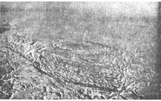
ice features by its high sails. Slopes may be relative- ly steep (vertical in some cases), probably due to erosion of parts of the rubble during the early stages of field formation. The relatively large bond strength between blocks will maintain such slopes. A tidal crack usually surrounds grounded rubble. It varies in shape and width according to the direction of the ice cover forces and the magnitude of the tide. As an example, the rubble field at Issungnak artificial island in 1980 is shown in Fig. 1.
A number of investigations of rubble fields as-
sociated with artificial islands have been carried out. Frederking and Wright (1982) measured sail and keel profiles, temperatures, salinities, voids and ice strength of the rubble field surrounding Issungnak island. Kry (1978) published the results of field ob- servations at Netserk B-44 island and also discussed design considerations. Kovacs (1981) studied ground- ed rubble fields on natural shoals in the Bering Sea.
Fig. 1. Rubble field at Issungnak artificial island, 1980.
At present the role of grounded rubble in trans- mitting ice cover loads to structures is not complete- ly understood. Although grounding resistance would decrease the force on the structure, the great width of the field might increase the total load from float- ing ice (Kry, 1978). Only simple estimates of ground- ing resistance and of shearing resistance of sections of rubble have so far been made (for example, Kry, 1978; Allyn and Wasilewski, 1979). No analytical treatment that takes into account the equilibrium and constitutive equations in constructing the stress field has been attempted. An idealized model of ice rubble fields is proposed in the present paper. Stress distribu- tions for a special case of rubble adjacent to wide structures are developed.
MODEL
An idealized model of grounded fields is pre- sented. Stress distributions will be determined for given boundary shape, sail height, and water or keel depths. The surrounding floating ice sheet is not in- cluded in the model and is considered to form a rigid boundary. Rubble strcsses at the boundary corre- spond to ice sheet loads required to maintain critical equilibrium of the rubble field.
The bulk rubble is treated as a continuum under- going two-dimensional deformation in a horizontal plane, a reasonable assumption in most cases where the horizontal dimensions of the field are large com- pared to rubble height. This height is assumed to have a constant average value. Height of the rubble does not appear explicitly in the analysis, but it will impose a limit on the magnitude of stresses.
A sketch of the case under consideration is shown in Fig. 2. The field has length L and is symmetrical about the x-axis. Width of the field can be given by any arbitrary function w(x). The structure (at x = 0) covers the whole width of the field.
Consider the total load an ice cover exerts on the rubble field in the direction of the structure (negative x-direction). The grounding shear stresses would act on the keel in the opposite direction (positive x - direction). The local directions may deviate some- what, being opposite the displacement directions. There is much uncertainty regarding grounding, and, in order to reduce the complexity of analysis, it is
S T R U C I U R E
F I E L D
+
XFig. 2. Sketch of grounded rubble field.
assumed here that grounding stresses act in the posi- tive x-direction. Such shear stresses can be accounted for by adding body forces to the rubble. Their mag- nitudes are considered to be too small to cause any appreciable deviation from two-dimensional deforma- tion (or plane strain), and the vertical stress (per- pendicular to the x-y plane) remains approximately a normal principal stress. The interaction between rubble keel and seabed is a complex phenomenon. It is assumed that grounding resistance to the keel is simply equal to a coefficient of friction (p) mul- tiplied by the normal stress between keel and seabed. Although no precise value of p is available, a range of reasonable values within possible extreme limits may be employed. For example, the maximum value is limited by the shear resistance of seabed or rubble keel. As berms of artificial islands are always sloping, weight of the rubble on the berm would decrease with increasing distance from the structure. Thus, the body force is considered to decrease approxi- mately linearly with distance x ,
where b is the body force per unit volume and p is the bermlrubble coefficient of friction. The term (A, - h2 x) is the vertical normal stress at the rubble/ berm interface divided by an "effective" field thick- ness (considered here to be constant). It can easily be estimated for a given sail height, keel depth, and
rubble bulk weight. A different form of the ground- ing resistance dependence on x could be used as well, with only minor modifications in the following analysis.
The eguilibrium equations for the rubble field are
and
where ox, a,, and r are the normal and shear stresses in the plane of the rubble field and compressive normal stresses are considered positive..
Laboratory experiments on model ice rubble (Prodanovic, 1979) indicate that bulk rubble behaves as a Mohr-Coulomb material under a range of strain rates and stress levels covering most cases of present interest. Apparent similarities of shape and of mode of deformation between ice rubble and granular materials support this conclusion. The bulk rubble is considered here to be a rigid-plastic continuum obeying the Mohr-Coulomb yield criterion; volume changes during deformation are neglected. Properties of the rubble are expected to depend on its age and temperature history. There are no published data that quantitatively account for this. The present analysis is intended for newly formed rubble fields subjected to loading or deformations occurring over relatively short periods. Rubble properties are assumed to be constant. Although it may be possible to extend the analysis to treat older, highly cohesive rubble, there is uncertainty regarding the yield criterion and material properties.
Yield occurs along a surface if the shear stress exceeds a critical value given by
2 7 , = us tan
4
+
c
(4) where T, is the critical shear stress, us is the normalstress,
4
is the angle of internal friction and C is cohesion.The yield criterion is satisfied by expressing the stress components as follows
o x = p + q c o s 2 J ,
and
where p is the average normal stress and J, is the angle between the major principal stress and the positive x-direction. The stresses p and q are given by
and
where 01 and on are the major and minor principal stresses, respectively. The yield condition (eqn. 4) is satisfied along two planes making angles 5
(n/4
-@/2) to the direction of the major principal stress. The contact forces between the blocks and, in turn, overall cohesion will tend to increase with in- creasing pressure. It appears, therefore, to be reason- able to assume that cohesion is proportional t o the average normal stress, although there is not suf- ficient evidence t o prove it. A simple equation for cohesion is
In this case the governing equations can be written in a form similar to that for cohesionless materials, using the equivalent angle of internal friction
@' = sin-' (sin @
+
k cos @).
(10) The following analysis, however, is valid also for constant cohesion, with angle @ replacing9'.
When rubble fields form in staies and thus have non-uni- form cohesion, the foregoing assumption does not necessarily apply. In such cases the present analysis would have to be modified.ANALYSIS
The method of integral relations is used to solve eqns. (1-10) for the stress field. This approach is based on assumption of general forms for variation of the dependent variables, then integration of the governing equations over a number of strips across the width of the field. The resulting ordinary dif- ferential equations can be solved to obtain the param- eters used in the assumed forms of the variables.
This procedure was used by Savage (1967) and by Savage and Sayed (1979) to determine the stresses and flow rates of granular materials in hoppers. The stress, q , and angle, J / , for a symmetrical field are even and odd functions, respectively, of the distance, y , and may have the general forms
A simple version of the integral relations method
is employed in the present study to avoid lengthy algebra, but it clearly illustrates the trends in behav- iour. A one-strip method is used. Thus, the governing equations will be integrated from y = 0 to y = w .
Furthermore, stress, q , is considered to have an average constant value across the width of the field, i.e., only the first term in the right side of eqn. (1 1) is used. Savage and Sayed (1979) found that a some- what similar approximation gives reasonably accurate results. The stress angle, J / , is assumed to have a linear variation from the centreline of the field
OI
= 0 )t o the boundary
O,
= w). As the present problem cor- responds to the active state (a,>
a,,), $ should be zero at the centreline. Considering the boundary of the rubble field to be rough, the ratio of shear and normal boundary stresses (7, and a,) would be~ , / a , = tan $'
.
( 1 3 )This gives the value of J, at the boundary
J/*
= n/4 - 4'12+
tan-' (dwldx).
(14)The distribution of J/ becomes
The previous assumptions leave only the function qo(x) to be determined. Only the x equilibrium equa- tion ( 2 ) will be integrated. Note that employing more terms from eqns. (1 1) and (12) would require the use
of both equilibrium equations integrated over a num- ber of strips, depending on the number of unknown functions. Substituting eqns. ( I ) , (S), (6) and ( 9 ) in (2) gives
a40
a
$(cosec $'
+
cos 21))-
- 2 qo sin 2 J /-
ax a x
Employing eqn. ( I S ) , each term in eqn. (16) is in- tegrated with respect t o y from y = 0 t o y = w to give
the following ordinary differential equation:
(
cosec4'
+-
1 sinz$*)
w dqo 2+
[ F
X2J/*
1
J/*
dw(-
sin 2$*--
cos 2)*)-
+sinZ G * ]
qo4 2 dx
Equation (17) can be integrated numerically for any arbitrary boundary shape given by w(x). One bound- ary condition is needed in order to determine qo(x). It is convenient to start the calculations from a given value at x = 0 and proceed to the corresponding stress distribution. The value of qo can then be related to rubble boundary stresses.
For the special case of wedge-shaped rubble fields, the boundary is given by
w
= ( L -x)
tan a ( 1 8 )where a is half the apex angle of the wedge. A closed- form solution is obtained for this case.
where 7 , is the unit weight of water
2 t a n a 1
B = sin 2 -
-
(-
sin 2-2.
cos 2$*)J/*
4 2and
T-I = B/A
Taking the value of q at x = 0 (q*) as an initial con-
dition, the integration constant K would be
4* P O , + A z L )
K =- - tan a
+
p A 2 L t a n a TwL Tw (B - A ) Tw (B -- 2-4)(21)
Stresses in these equations were normalized using a stress ywL and length L . The reference values
are merely for convenience and have no physical sig- nificance to the present problem. The use of a differ- ent reference stress or length would only result in multiplying all terms by a constant.
DISCUSSION O F RESULTS
The analysis is intended for narrow rubble fields with a structure traversing their complete width. The integral relations approach may be extended to treat wider rubble fields surrounding islands by using a two-strip method and more general forms for the variation of the variables.
Typical results are shown in Fig. 3 for a wedge- shaped rubble field. The non-dimensional stresses, p/ywL, q / y w L , normal boundary stress, u n / y w L ,
and centreline stresses, uf/rwL and uy/ywL, are given for
a
= lo0,4'
= 50,
p = 0.4, hl/yw = 0.067 and X,L/yw = 0.233. This choice of body force parameters corresponds to an approximate sail height of 2 m, water depth of 5 m at the structure, berm slope of 9", and structure width of 100 m. The nor- mal stress at the berm is divided by an average field thickness of 13.5 m. Grounding occurs up to a distance x/L-
0.29; rubble is assumed to be floating for x/L>
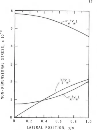
0.29. The stress distribution across the width of the field at the structure is shown in Fig. 4. These stresses should be multiplied by rubble average height to give forces per unit length. Several values for the initial value q* at the structure (x = 0) were used in Fig. 5. Each gives a stress distribution corre- sponding to a different magnitude of floating ice loads (or rubble field boundary stresses). The stressest
GROIINDID J_ FLOAllNG AUBRLL I RU9Blt
0 0 1 0 2 0 3 0.4 0 5 0.6 0 7 0 8 0 9 L O
O I S T A N C E . x l L
Fig. 3. Longitudinal stress distribution for a = l o 0 , @' = 50°,
p = 0.4, h,/yW = 0.067 and h,L/yw = 0.233.
L A T E R A L P O S I T I O N , y / w
Fig. 4 . Stress distribution across width of field at x = 0 (a =
lo0, @' = 50°, p = 0.4, h , / ~ ~ = 0.067 and h,L/yw = 0.233).
s R U B B L E + R U B B l t X 1 R I N C R E A S I N G I N I T I A L I S T R E S S . a
:
;
0 0 0.1 1 . 2 0.3 0.4 0.5 0.6 0.7 0.8 0.9 1.0 DISTANCE, r/LFig. 5. Stress distribution for various maximum boundary stresses (a = lo0, @' = SO0, fi = 0.4, Allyw = 0.067 and h,L/yw = 0.233).
vanish at the wedge apex and increase towards the structure, reaching a maximum value, then decreas- ing again. Reduction of stress levels at the structure is caused by grounding resistance. Boundary stresses can be viewed as the limiting values that can be exerted by the surrounding floating ice t o keep a given rubble field in critical equilibrium.
The vertical normal stress in this two-dimensional analysis may have any value between the major and minor principal stresses. A constraint on the mag- nitude of the stresses the rubble can support may be obtained by considering the minor principal stress to be limited by the average vertical normal stress
p (1 - sin G')
<
uv (22)where a, is the average vertical normal stress in the rubble; it can be estimated from the weight of the sail, buoyancy of the keel, and rubble height.
The influence of the equivalent angle of internal friction, $', on stress distribution is illustrated in Fig. 6. The higher boundary stresses for larger values of $' are intuitively expected, since a "stronger" rubble would require higher ice loads to produce a given load on the structure. The role of grounding force is examined in Fig. 7 by changing the value of the coefficient of friction, p. It is clear that the difference between the stresses at the structure and
L [I
0 0 . 1 0 2 0 . 3 0 4 0 . 5 0 . 6 0 . 7 0 . 8 0 . 9 1 . 0 DISTANCE. x / ~
RUBBLE "; RUBBLE
I:&. 6 . Stress distribution for various angles of internal fric- tion (a = l o 0 . p = 0.4, Allyw = 0.067 and h,Llyw = 0.233).
DISTANCE. x / 1
Fig. 7. Stress distribution for various grounding resistances
(ol = l o 0 , @' = 50°, p = 0.4, h,lyW = 0.067 and h,L/yw =
0.233). J ...
-
- 4 - PARABOLA m ( w / L.
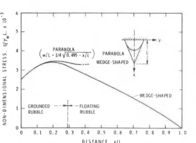
114 d m ) PARAWLA Z 0 0 0 . 1 0 . 2 0 . 3 0 . 4 0 . 5 0 6 0 7 0 8 0 9 1 0 D I S T A N C E , x / LFig. 8. Stress distributions for parabolic and wedge-shaped boundaries (a = l o 0 , @' = 50°, p = 0 . 4 , Allyw = 0.067 and h,L/yw = 0.233).
the maximum boundary stress is proportional to grounding resistance.
For simplicity, a wedge-shaped field was used in the above calculations. The present solution, how- ever, can give the stress distribution for any arbitrary boundary shape. For example, stresses for a parabolic boundary of the same width and slope dw/dx at
x = 0 are shown in Fig. 8. Note that d w / h = -=at the centreline of the parabola. The solution can only be evaluated for a region of moderate values of dw/dx. The predicted stresses for both wedge and parabola shapes are almost identical for small values of x/L, where the rubble field boundaries are similar. This implies that stresses near the structure are not affected by conditions relatively distant in the rubble field. Similar behaviour is observed for granular materials in hoppers and bins, where stresses are primarily affected by local conditions.
Loads on the structure can only be estimated for given values of maximum boundary stresses. For a rubble field with the dimensions and pararn- eters shown in Fig. 3, the average normal stress at the structure is
g,/rw~
= 5.7 X (from Fig. 4). The maximum normal stress at the boundary01
= w )is un/y,L = 1.9 X The ratio between the two is therefore 3. To determine the total load, an ap- propriate value of the maximum boundary stress must be selected. Kry (1980) has pointed out that ice sheet strength depends on the area under con- sideration. Generally, it decreases with increasing area. As may be seen in Fig. 3, the maximum normal
boundary stress in this example acts on a length of approximately 0.2 L (or 50 m). For this length of contact a reasonable maximum boundary force may be taken as 1.5 X l o 6 N/m (stress of 1 MPa and ice sheet thickness of 1.5 m), giving a total load of 45,000 tonnes on the 100 m width of the structure.
CONCLUSION
Calculated stress distributions in rubble ice can be helpful in the design and interpretation of field ex- periments. The results of the present study indicate that bulk rubble properties and rubblelberm friction can significantly influence stresses acting on a struc- ture. Field measurements are still, however, needed to clarify such factors. The present model can also aid in predicting the total loads on structures if stress in the surrounding ice sheet is known. A more general model that includes ice sheet behaviour is required for precise estimates of such loads.
ACKNOWLEDGEMENT
This paper is a contribution from the Division of Building Research, National Research Council Canada, and is published with the approval of tlie Director of the Division.
NOTATION
coefficients given by eqn. (20) body force
cohesion of bulk rubble height of rubble
parameter used in eqn. (9)
length of wedge-shaped rubble field average normal stress
stress given by eqn. (6) initial value of q at
x
= 0functions used in eqn. (1 1) half width of rubble field half angle of wedge-shaped field unit weight of water
paranieter given by eqn. (20) constant given by eqn. (2 1) parameters in eqn. (1)
keellberm coefficient of friction
normal stresses in
x
and y directions normal stress at the boundary of the fieldnormal stress on a yield surface average vertical normal stress major principal stress minor principal stress shear stress in x-y direction critical shear stress
shear stress along the boundary of the field
angle of internal friction
equivalent angle of internal friction angle between major principal stress and x-direction
value of
9
at boundary y = w functions used in eqn. (12)REFERENCES
Allyn, N. and Wasilewski, B.R. (1979). Some influences of ice rubble field formations around artificial islands in deep water. In: Proc. Port and Ocean Engineering under Arctic Conditions, University of Trondheim, Norwegian Institute of Technology, Trondheim, Norway, pp. 39-56. Frederking, R.M.W. and Wright, B. (1982). Characteristics
and stability of an ice rubble field, Issungnak, February- March 1980. In: Proc. Workshop on Sea Ice Ridging and Pile-up, Calgary, Alberta, Canada. Tech. Memorandum 134, Associate Committee on Geotechnical Research, National Research Council Canada.
Kovacs, A. (1981). Sea ice rubble formations off the north- east Bering Sea and Norton Sound coasts of Alaska. In: Proc. Port and Ocean Engineering under Arctic Condi- tions, Laval University, Quebec, Canada, pp. 1348-1363. Kry, P.R. (1978). Ice rubble fields in the vicinity of artificial
islands. In: Proc. Port and Ocean Engineering under Arctic Conditions, Memorial University of Newfoundland, St. John's, Newfoundland, Canada, pp. 200-21 1. Kry, P.R. (1980). Third Canadian Geotechnical Colloquium:
Ice forces on wide structures. Canadian Geotechnical J. 17: 97-113.
Prodanovic, A. (1979). Model tests of ice rubble strength. In: Proc. Port and Ocean Engineering under Arctic Condi- tions, University of Trondheim, Norwegian Institute of Technology, Trondheim, Norway, pp. 89- 105.
Savage, S.B. (1967). Some Considerations of Flow of Co- hesionless Granular Solids. Ph.D. Thesis, McGill Univ., Montreal, Canada.
Savage, S.B. and Sayed, M. (1979). Gravity flow of cohesion- less granular materials in wedge-shaped hoppers. In: S.C. Cowin (Ed.) Mechanics Applied to the Transport of Bulk Materials, AMD-3 1, ASME, pp. 1-24.
T h i s paper, w h i l e being d i s t r i b u t e d i n r e p r i n t form by t h e D i v i s i o n of B u i l d i n g Research, remains t h e c o p y r i g h t of t h e o r i g i n a l p u b l i s h e r . It should n o t be reproduced i n whole o r i n p a r t w i t h o u t t h e permission of t h e p u b l i s h e r . A l i s t of a l l p u b l i c a t i o n s a v a i l a b l e from t h e D i v i s i o n may be o b t a i n e d by w r i t i n g t o t h e P u b l i c a t i o n s S e c t i o n , D i v i s i o n of B u i l d i n g R e s e a r c h , N a t i o n a l R e s e a r c h C o u n c i l of Canada, O t t a w a , O n t a r i o , K I A 0R6.