Code Compaction and Parallelization for
VLIW/DSP Chip Architectures
by
Tsvetomir P. Petrov
Submitted to the Department of Electrical Engineering and Computer
Science
in partial fulfillment of the requirements for the degree of
Master of Engineering
at the
MASSACHUSETTS INSTITUTE OF TECHNOLOGY
June 1999
©
Tsvetomir P. Petrov, MCMXCIX. All rights reserved.
The author hereby grants to MIT permission to reproduce and
distribute publicly paper and electronic copies of this thesis docume
in whole or in part.
LIBRAR Author ... ... ,... ...
Department of Electrical Engineering and Computer Science
May 21, 1999
Certified by.
...
Saman P. Amarasinghe
Assistant Professor, MIT Laboratory for Computer Science
Thesis Supervisor
Accepted by ...
..
.Arthur C. Smith
Chairman, Departmental Committee on Graduate Theses
Code Compaction and Parallelization for VLIW/DSP Chip
Architectures
by
Tsvetomir P. Petrov
Submitted to the Department of Electrical Engineering and Computer Science on May 21, 1999, in partial fulfillment of the
requirements for the degree of Master of Engineering
Abstract
The Master of Engineering Thesis presented in this paper implements an assembly code optimizer for Discrete Signal Processing (DSP) or Very Long Instruction Word (VLIW) processors. The work is re-targetable and takes as input minimal generalized chip and assembly language syntax description and unoptimized assembly code and produces optimized assembly code, based on the chip description. The code is not modified, but only re-arranged to take advantage of DSP/VLIW architecture paral-lelism. Restrictions are placed to make the problem more tractable and optimality is sought using linear programming and other techniques to decrease the size of the search space and thus performance close to that of native compilers is achieved, while maintaining retargetability. This document discusses motivation, design choices, im-plementation details and algorithms, performance, and possible extensions and ap-plications.
Thesis Supervisor: Saman P. Amarasinghe
Contents
1 Introduction
1.1 M otivation . . . .
1.1.1 Hand Optimization Techniques are not Scalable . . . . 1.1.2 Hand-Optimized Code is not Portable . . . .
1.1.3 Code Optimizer as an Evaluation Tool for New Chip Designs 1.2 Benefits of Focusing on VLIW/DSP Chip Architectures . . . .
1.2.1 Widespread Use and Variety of Algorithms . . . . 1.2.2 Generally More Limited Instruction Set and Simpler Pipelines
1.2.3 Design Peculiarities Make Optimizations Difficult . . . . 1.2.4 Performance Requirements Justify Longer Optimization Times
2 Approach
2.1 Related W ork . . . . 2.2 Attempt at Retargetable Optimality . . . . 2.3 Restricting the Problem to Re-arranging Code . . . . 2.4 Generalized Chip and Assembly Language Description . . .
2.5 Assuming Memory Aliasing and Basic Block Self-Sufficiency
2.6 M odularity . . . .
3 Module Overview
4 Describable Chip Architectures
4.1 Description Sem antics . . . . 12 . . . . . 12 . . . . . 13 . . . . . 14 . . . . . 14 . . . . . 15 . . . . . 15 17 20 20 7 8 8 8 9 9 9 9 10 10
4.1.1 Multiple Instruction Issued on the Same Cycle . . . . 20
4.1.2 Pipeline Delay Slots Support . . . . 21
4.1.3 Resource Modification Oriented Description . . . . 21
4.1.4 Conditional Instruction Execution Support . . . . 22
4.1.5 Support for Common Control Flow Instructions . . . . 22
4.2 Chip Description Syntax . . . . 23
4.2.1 Convenience Features . . . . 23
4.3 Exam ples . . . . 24
4.3.1 Overview of TMS320C6201 . . . . 24
4.3.2 Sample Instruction Definitions . . . . 26
5 Data Dependency Graph (DDG) 28 5.1 Parser O utput . . . . 28
5.2 Fragmentator . . . . 28
5.2.1 B asic Case . . . . 29
5.2.2 Special Cases . . . . 29
5.2.3 Optimization Controls at Fragmentator Level . . . . 30
5.3 DDG Builder . . . . 30
5.3.1 Correctness Invariant . . . . 30
5.3.2 Handling of Beginning and End of Block . . . . 31
5.3.3 Properties of This Representation . . . . 31
5.4 Live Range Analysis and Optimizations . . . . 32
6 Optimization Framework 6.1 General Framework . . . . 6.2 Basic Steps at Every Cycle . . . . 6.3 Definition of Terms . . . . 6.3.1 Dynamic Link Properties . . . . 6.3.2 The Ready List (LR) and the Links-to-unready List 6.3.3 Node Properties . . . . 6.4 Generation of All Executable Combinations . . . . (LUL) 34 34 34 35 . . 35 36 . . 36 37
7 Dynamic Constraint Analyzer 7.1 A Simple Example ...
7.2 Dynamic Constraints ...
7.2.1 Dynamic Constraint Analysis is Necessary
7.2.2 Greedy Might not Guarantee Any Solution
7.3 Types of Constraints . . . .
7.4 A lgorithm . . . .
8 Linear Programming Bound Generator
8.1 Expressing The Problem As Linear Program . . . .
8.2 Limitations Of Linear Programs . . . .
8.3 Static Bounds and User-Defined Heuristic Bounds . . . .
38 . . . . 38 . . . . 41 . . . . 42 . . . . 42 . . . . 43 . . . . 45 47 47 47 48 9 Optimizations, Heuristics and Results 49 9.1 Better or Faster Bounds . . . . 49
9.2 Prioritization of Combinations to Try . . . . 50
9.3 R esults . . . . 51
9.3.1 Better than Native Compiler . . . . 51
9.3.2 Two Examples of Simple Retargeting . . . . 51
9.3.3 Sample Code Fragment . . . . 53
10 Extensions and Applications 56 10.1 Extensions . . . . 56
10.2 Applications . . . . 57
10.2.1 Evaluation Tool for New Chip Designs . . . . 57
10.2.2 Porting Existing Code . . . . 57
10.2.3 Last Phase of Optimizing Compiler . . . . 58 59 60 11 Conclusion
List of Figures
3-1 Module Overview
4-1 4-2
TMS320C6201 Schematics, [24] . . . .
Sample Definition of Addition Instructions
7-1 Sampe C Code Fragment . . . . .
7-2 Sample Assembly Translation . .
7-3 DDG Graph of Sample Assembly
7-4 Solution of Original DDG . . . . 7-5 Solution of Modified DDG . . . . 7-6 RPL-RPL Constraints . . . . 7-7 DS-RPL Constraints . . . . 7-8 RPL-DS and DS-DS Constraints.
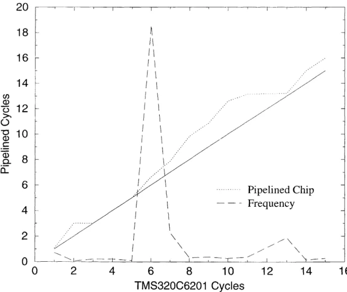
9-1 Performance Comparison Example
9-2 Sample Assembly Block for Different Chips .
. . . . 18 25 26 . . . . 3 8 . . . . 3 9 . . . . 3 9 . . . . 4 0 . . . . 4 0 . . . . 4 3 . . . . 4 4 . . . . 4 4 . . . . 5 2 54
Chapter 1
Introduction
In recent years the advances in process technology and chip design have led to many high performance chips on the market, at more and more affordable prices per com-putational power. At the same time, the "smart devices" model of computation has also been gaining ground, giving rise to a large variety of embedded systems utilizing high performance, often highly specialized chips.
In particular, many of those chips have been designed to address the needs of signal processing application such as digital communications and digital television, computer graphics, simulations, etc. Being intended for a large production volumes, cost has been an even more pressing issue and a lot of the designs do not have the complicated optimization circuitry doing branch prediction, pre-fetching and caching, associated with modern general purpose microprocessors.
Because of the simplicity of the hardware design, which makes parallelism very explicit to the user, most of the optimizations have been left to the programmer. Still, providing optimal or nearly optimal solutions to the optimization problems in the transition to high performance chips has been both interesting, challenging and difficult.
This work presents an attempt at optimal or nearly optimal utilization of com-puting capabilities for high-performance chips. Given an unoptimized or partially optimized assembly code, this software tries to produce optimal or nearly optimal version of the same code for a specific DSP/VLIW chip. In order to make the work
more practical, fairly general chip descriptions are allowed.
1.1
Motivation
1.1.1
Hand Optimization Techniques are not Scalable
While code parallelization of assembly code for VLIW/DSP chips has been an active research issue for decades, in most cases even now, assembly code for powerful DSP and other VLIW chips is hand-crafted and optimized. Unfortunately, a lot of the techniques employed by humans in this process (if any systematic techniques are employed at all) do not scale very well. For example, the introduction of the Texas Instruments TMS320C6000 series, capable of issuing up to 8 instructions with variable pipeline lengths per cycle, marks a new era, where it becomes increasingly hard to hand-optimize code with that much parallelism, and in fact, to even write remotely optimal code. In fact, one can argue that software such as the one presented here, extended with more high-level optimizations, could often produce better results than humans on long and algorithmically-complicated code. Thus, given the tendency of creation of even more powerful chips and the use of more convoluted algorithms, scalability becomes more and more important issue.
1.1.2
Hand-Optimized Code is not Portable
Not only techniques for hand optimization are not scalable, but they are also not portable. Historically, each generation of DSP chips has been taking advantage of process technology to optimize the instruction set architecture, because it is too costly in terms of power and gates to emulate a single instruction set architecture. Thus, with the introduction of new more powerful and different chips, all optimizations to existing code need to be re-done, which is a long and difficult process, involving both coding, optimization and validation. A generalized tool that provides good code optimization, such as the one presented here, would certainly make the transition much faster.
1.1.3
Code Optimizer as an Evaluation Tool for New Chip
Designs
In addition to easing the transition between generations of chips, a code optimizer, extended with simulation or profiling capabilities can be very helpful in determining what features in a new chip are most useful. Given the long turnaround times in hardware design and the often fixed application code, a tool enabling specification of hardware capabilities and providing ballpark figures for running time of optimized code, could be very valuable just for that reason.
1.2
Benefits of Focusing on VLIW/DSP Chip
Ar-chitectures
1.2.1
Widespread Use and Variety of Algorithms
Well, obviously, in order to talk about parallelization, we have to have the capability of executing many instructions in parallel and DSP/VLIW chips have this capability. In addition, they are widely used and very likely to grow in both usage and capabilities. Given the variety of applications those chips are used for (and the tendency of this variety to grow, for example, with the introduction of Merced, (backwards compatible with Intel x86 family)), seeking a general-purpose solution versus trying to optimize every algorithm for every chip is a better approach.
1.2.2
Generally More Limited Instruction Set and Simpler
Pipelines
Since code parallelization is a hard problem, trying to solve it on a simpler architec-tures is helpful. Since most DSP/VLIW chips have a more limited instruction set and their pipelines are relatively simpler, one can achieve better optimization results.
1.2.3
Design Peculiarities Make Optimizations Difficult
While some of the high-performance DSP/VLIW chips (such as TI TMS320C6000 series) have had a very general, streamlined design, many of the older and more specialized DSP chips have had a very programmer-unfriendly design. In particular, because of the limited width of the instruction words, in high performance instruction word encodings only certain combinations of operands might be allowed, while in easier-to-encode, but less parallel instruction words all combinations are present. For example, on Qualcomm's proprietary QDSP II, in a cycle with 5 parallel instructions, the operands of multiply-accumulate instruction can only be certain sets of registers, although data paths exist for more registers to be operands and indeed, if the MAC instruction is combined with less instructions, more operand register sets can be used. While the above problems are especially acute with more specialized chips, they are present in most VLIW/DSP chips to some extent. Thus, just learning what the instruction set is, can be an involved process with programmer's manuals easily exceeding hundreds and often a thousand of pages. While all those issues make optimization more difficult for both humans and compilers, as discussed in Section 1.1, only compilers are capable of providing scalable and portable solutions.
1.2.4
Performance Requirements Justify Longer
Optimiza-tion Times
Finally, last, but not least, most of the applications currently running on DSP/VLIW chips are applications in a framework of very limited resources and very rigid require-ments - both in terms of data memory, instruction space, and running time.
In addition, because many of them are used in embedded systems, often the problems solved are smaller and more self-contained and easier to achieve optimal or near-optimal results.
Finally, in embedded systems, even if resources are available, optimizations are still
highly desirable, because of power consumption considerations, which often require
Thus, contrary to general purpose processors where performance might be sac-rificed for speed of compilation, with most applications on DSP/VLIW chips, it is imperative that the the code is highly-optimized and therefore, slow, but good tools, as the one proposed here, are viable.
Chapter 2
Approach
Having described the motivation and the focus of the project, it is now time to define its place amidst other work in the field and define more clearly its objectives and approach to achieving them.
2.1
Related Work
There has been a fair amount of work in the field with many semiconductor compa-nies releasing powerful chips and compilers that do some optimizations as commercial solutions. In fact some of the inspiration behind this work come from looking of older version of assembly optimizer tools running in real time and attempting to achieve better and more general solutions. The latest version (February, 1999) of the Op-timizing C Compiler and Assembly Optimizer [24, 25, 26, 27] for TMS320C6201 by Texas Instruments is used for comparison and examples, throughout this paper. In fact they produce very good (but not always optimal) results but are limited by de-velopment time and real-time compilation constraints. In addition, such commercial tools are understandably non-retargetable.
Besides commercial code optimization solutions there has been a lot of research into retargetable compilation. Most of the proposed solutions are complicated and encompassing all from structural chip specification, register allocation and instruction scheduling. MIMOLA ([22]), for example, starts from net list structural description;
AVIV ([11]), CodeSyn ([23)) and Chess ([14]) start from somewhat higher level chip description, but go through register allocation, mapping high level instructions into assembly ones using tree covering and code compaction (as presented in this work). Solutions like those have more potential for overall improvement, but employ heuristic solutions for code compaction and most likely would benefit from replacing their code compactor with the tools in this paper.
Other publications relevant to this include work on languages for chip description (several varieties, depending on granularity [17, 19] - some not much different than the one chosen in this work) and work on dynamic programming, linear programming (Wilson et al, [16]) and other techniques
([1-10])
for code compaction. Many of those techniques are computationally infeasible (such as solving the entire optimization problem as a single integer linear program) or partially used in this work (linear programming for obtaining bounds), or inapplicable, because of different computation framework.2.2
Attempt at Retargetable Optimality
Amidst many complicated solutions, the intent of this work was to be fairly practical and thus the following emerged as main priorities:
" simple, but retargetable, chip and assembly description - the first step to opti-mizations is describing the chip architecture - if this is a daunting task, people might as well not even attempt it
" attempt at optimal solutions - unlike many other tools, this work makes an attempt at provably optimal solutions, given some constraints
" attempt at capturing many varieties of architectures, but not at the price of less
optimizations - if some instructions cannot fit in the optimization framework, they are left unchanged
" devising simple, yet powerful, assembly and chip description language " using techniques to make optimizations more tractable
" describing extensible infrastructure for doing such optimizations
2.3
Restricting the Problem to Re-arranging Code
Probably the most restrictive choice in achieving simplicity, was that code was not to be modified, but just re-arranged. All valid re-arrangements allowable by the data dependency constraints are considered, however. This requirement might seem too restrictive from optimization point of view, but in practice it is not, if all other standard optimizations such as dead code elimination, constant propagation, common subexpression elimination and so on, are already performed. Peephole optimizations can be used to find better instruction combinations.
In fact, the standard compiler optimizations are only applicable if compiling from a high-level language - if the input is hand-crafted, those usually do not even apply. In addition, this code can run standalone after any other opimizing compiler has done its job, which is a good from systems design perspective.
2.4
Generalized Chip and Assembly Language
De-scription
In order to make the work more practical, a fairly general chip description is allowed at a conveniently high level. In particular, the chip is described in terms of combinations of assembly instructions that can be executed in a single cycle. The description of assembly instructions itself contains both parsing information to allow describing a fairly general custom assembly language syntax as well as information on data dependencies and branch delay slots associated with every instruction.
Describing the system at a such a high level is simpler and easier and has the added advantage of being less prone to errors than a lower level hardware description
in terms of functional units and datapaths.
2.5
Assuming Memory Aliasing and Basic Block
Self-Sufficiency
In order to determine whether memory accesses are aliased or not, a whole new framework and a lot of infrastructure need to be created, and, it is still impossible to always determine that at compile time, especially when dealing with identifiers and/or pointer arithmetic inherited from a higher-level language (such as C). Thus, in this work all memory accesses to the same memory unit are assumed to be dependent.
Similarly, by default, all labels are considered possible entry points (to allow for optimizing of single components of a large hand-optimized application, for example) and they limit the size of basic blocks for optimization purposes. For those purposes, all calls or jumps are also delimiters, because of the difficulty (or impossibility) of ob-taining information for required and modified resources for arbitrary (or non-present) procedures. Some of those restrictions can be relaxed, through user hints, however. Furthermore optimizations such as loop unrolling and trace scheduling can be used to provide larger blocks, if necessary.
2.6
Modularity
Modularity as a design choice is present in two levels:
" The optimization tools employ modular design in order to allow for extensibility
and maintainability. An attempt at defining simple and easy to debug interfaces between modules has been taken and indeed many of the modules can be easily replaced or modified without major modifications to the rest of the code. An overview of all modules can be found in Chapter 3.
" The optimizations are performed in modular fashion in order to guarantee
sound too restrictive, in practice it is not, because often, in general, code cannot be moved outside certain bounds (see Section 2.5). An added benefit of this modular approach to processing is that this work might further be parallelized or restricted to optimizing just parts of application code with very little effort.
Chapter 3
Module Overview
Figure 3-1 contains a diagram of the basic modules of the optimizer and the flow of data through them. The process of optimizing assembly files for a particular
architecture can roughly be partitioned into 3 phases:
* The first pre-requisite is to describe the chip capabilities and assembly syntax
and run it through the Chip Description Analyzer and Parser Generator tool. This only needs to be done once per chip description. Those tools generate a parse tree and other data structures representing the chip for use later in the process and can easily be modified or replaced to suit other assemblies or different chip description styles. More detail on the input language and examples can be found in Chapter 4.
* Having created the necessary infrastructure to support given assembly syntax
and chip capabilities once, one can run many assembly files through the op-timizer. However, since it is desirable to take most of the work out of the optimization loop, the code goes through several transformations before arriv-ing there. In particular:
- The code is being parsed into internal representation using predictive parser (allowing for a wider range of grammars to be supported).
- The code is then split into basic blocks. Doing so is essential for scalability. It is also useful as an abstraction barrier. For the motivation of making this
Chip Description
Chip Description Analyzer Assembly Parser Generator Assembly Code
Search Engine
[
Heuristics and User-Guided SearchI
=Linear Programming Bound Generator Dynamic Constraints Analyzer
a separate stage and discussion of some of the issues involved in splitting the graph see Section 5.2.
- Once the code is fragmented into basic blocks, a data dependency graph (DDG) preserving the most parallelism is derived. Note that the represen-tation and terminology used in that is somewhat innovative. See Chapter 5 for more details.
- Even though the data dependency graph is a representation of the opti-mization problem preserving correctness, there are additional properties of the data dependency graph (DDG) that would enhance the search for solution. They are described in Section 5.4.
Finally, given a data dependency graph and attempt at an optimal or nearly optimal is made. The basic search framework is branch and bound with bounds provided using linear programming, minimum distance to end and other meth-ods, heuristic hints and directions provided by the user and an early detector of futile branches of the search space. All those components are closely interleaved in the code, but they are described in separate chapters, because each one of them contains interesting algorithms and other issues.
Chapter 4
Describable Chip Architectures
Having described the scope of the project and given an overview of the tools, it is now time to focus in detail on the range of chips describable within Assembly Description Language (ADL) of this project. The general idea of the language is to be able to describe the syntax of all assembly instructions together with with the minimum required information about how they can be reordered. In order to highlight the process of arriving at that language the supported features will be described first.
4.1
Description Semantics
All chip architectures that can be described correctly within the description semantics
listed below can benefit from this work. Furthermore, even if the chip as a whole cannot be fully or correctly described within this framework, often by eliminating offending instructions or situations (eg. waiting and servicing interrupts, etc) from consideration, one could make this work applicable to many more architectures.
4.1.1
Multiple Instruction Issued on the Same Cycle
The description of the chip capabilities is in terms of assembly instructions capable of being issued at the same cycle. In the simple case of non-pipelined processors this translates to sets of instructions that can execute together in a single cycle. In fact, all
pipeline stages common to all instructions can be viewed as occurring in a single cycle for the purpose of extraction of data dependencies from the source code in the case of pipelined processors with same length non-blocking pipelines for all instructions and no delay slots. Eliminating stages in this fashion is helpful when reasoning about the chip.
4.1.2
Pipeline Delay Slots Support
Recognizing, however, that many chips feature variable length instruction pipelines and delay slots (most commonly with branches, but also with other instructions) such capabilities are also supported. Different delay slots for different resource updates are also supported. An example of such situation would be a memory load instruction with address register modification. The address register modifications typically are in effect for the instructions issued on the next cycle, while the register getting data read from memory might not be modified until several cycles later.
4.1.3
Resource Modification Oriented Description
The description of the chip functionality for the purposes of detecting dependencies is based on specification of used and modified resources for each instruction. Registers are typical such resources. Each instruction lists the registers it requires and modifies. For the purposes of defining the chip semantics correctly unlimited number of other resources can be defined with the same semantics as registers. Memory is a typical example of such resource. Such additional resources can be used to capture "hidden" registers such as the ones used in stack modifications, register flags, special modes of operations and more. See Section 4.3 for examples.
Here are some of the key properties of that description (for simplicity, single-cycle execution terminology is used; non-blocking pipeline semantics are the same):
* The values of all used resources are assumed to be read at the very beginning of the cycle. Thus, if the same resource is used and modified at the same cycle, the old value is used in computation.
" The modification of all modified resources is assumed to happen at the end of
the current cycle (ie. the modified value is to be used for the instructions issued on the next cycle), unless delay slots for the modification of that resource are specified, in which case the change is assumed to happen the specified amount of delay slots later.
e The same resource cannot be modified by two different instructions in the same cycle, because of unresolved ambiguity about the order of modification.
" Each resource can be used by any number of instructions and any number of
operands in a given cycle. To describe more stringent constraints based on use of hardware data paths and so on, one could introduce resources for those data paths and specify their modification as required (see Section 4.3 for examples).
4.1.4
Conditional Instruction Execution Support
Many modern chips allow conditional execution of instructions based on the value of a certain register or flag. Conditional jumps or loops are the most essential examples of such instructions, but support for any conditionally executed instruction is included. Unless there is control flow transfer the semantics of those instructions are not much different than any other instructions - the only difference is that the register or flag being tested is an "used resource" in the above sense.
4.1.5
Support for Common Control Flow Instructions
Control flow operations are problematic in chip descriptions because they are less standardized in encoding and functionality from chip to chip. Specialized loop in-structions and their placement right before, after or within the loop body can be a problem in describing the chip assembly and capabilities. Several common cases of such placements are supported. The work can easily be extended to support oth-ers. Calls, jumps and other similar instructions are supported, together with their conditional and delay slot versions. For complete description see Section 5.2.
4.2
Chip Description Syntax
For an added convenience and ease of description, the description of the chip will consist of description of all possible valid instructions in assembly. Note that the description might aceept invalid entries as well, as long as it is not ambiguous - on invalid input, the output is guaranteed to be invalid! All instructions, then, would be partitioned into instuctions sets or classes, such that all instructions in the same class combine in the same way with all other instructions (for example the class of ALU instructions). Finally, all possible combinations of instructions that can occur on a single cycle will be described in terms of instruction classes. Note that a class can consist of a single instruction, if it combines uniquely with instructions from other classes.
The description of a single instruction or a several instructions together when using shortcuts (see below) consist of a name, list of tokens and 3 other lists (optionally empty). The 3 additional lists are used to determine the data dependencies and are requires, modifies and special list respectively. Each element of the requires and
modifies lists is either a number indicating which token in the token list (representing
register) is meant, or a string identifying other resource or a particular register. An entry in the modifies list starting with the symbol '#' signifies signifies delay slots in the modifications of the resource immediately preceding it. The special list contains the type of a control-flow operation (eg. conditional, JUMP, JUMPD, CALL) and other information, if necessary.
4.2.1
Convenience Features
In order to make the process of describing the chip and its assembly language easier the following are supported:
* sets of registers
e use of - to signify optional nothing or several tokens always used together (eg.
<< 16) in operator descriptions
" the special token STRING matches any alphanumeric sequence - useful as a placeholder for constants or identifiers in the source code
" definition of related resources (eg. if RO is 16-bit and its 8-bit parts are ROh and
RO1, then whenever RO is modified, ROh and RO1 are modified and vice versa)
-useful in register sets
4.3
Examples
Having described the describable chip architectures in general and the description syntax features in detail, it is now time to give some examples.
Some of the chip architectures described within this framework include QDSP II by Qualcomm Incorporated and TMS320C601 by Texas Instruments. However,
QDSP
II is Qualcomm proprietary and therefore will not be used for examples, while information about TMS320C6201 is publicly available and it is widely used chip, so the examples here will be based on it.4.3.1
Overview of TMS320C6201
TMS320C6201 is an Very Long Instruction Word chip, capable of issuing up to 8
instructions per cycle. Most instructions execute in a 11-cycle pipeline and the chip can be clocked at 200 MHz making it one of the most powerful fixed point integer
DSP chips on the market. It features two sets of nearly identical computational units
and two general purpose register files associated with each set. The shematic can be found on Figure 4-1. The L units perform long arithmetic operations such as addition and subtractions. The S units perform similar operations on different arguments. The M units perform 16 bit multiply operations and the D units perform memory loads and stores. The L, S and M units can only write to their register block, while the
Control register file
register path so only one of the arguments of the L, S, M units on each side of the chip can come from the other side. The arguments to the D units must come from their respective part of the chip.
RSet AX AO Al A2 A3 A4 A5 A6 A7 A8 A9 A10 All A12 A13 A14 A15
RSet BX BO Bi B2 B3 B4 B5 B6 B7 B8 B9 B10 Bl B12 B13 B14 B15
OSet ADDLX ADDL ADDLSU ADDLU ADDLUS
OSet Number STRING -_STRING ;
inst ADDL1 ADDLX AX , AX, AX; 2 4; 6;
inst ADDL2 ADDLX Number , AX , AX ; 4 ; 6
inst ADDL3 ADDLX BX , AX, AX; 2 4; 6 x1
inst ADDL4 [AX ] ADDLX AX , AX, AX; 2 5 7; 9 ; 13;
inst ADDL5 [AX ] ADDLX Number ,AX, AX ; 2 7 ; 9; 13;
inst ADDL6 [AX ] ADDLX BX , AX, AX; 2 5 7 ; 9 x1 ; 13;
ISet UnitL1 ADDL1 ADDL2 ADDL3 ADDL4 ADDL5 ADDL6 ;
Figure 4-2: Sample Definition of Addition Instructions
4.3.2
Sample Instruction Definitions
Given the above functionality of the chip and the format of its assembly, a sample
def-inition of a set of instructions executable on unit Li is given on Figure 4-2. (Note that the ISet definition above, in practice, should include all other instructions executable on that unit).
First AX and BX are defined as enumerations (sets) of registers. Then ADDLX is defined as the set of several different instruction mnemonics for addition - note that for the purposes of this work it is not important what the operation really is, as long as the required and modified resources are identified correctly. Since the addition instructions might make use of a constant operand, Number is defined as an optionally signed alphanumeric sequence. Here, again the value of the operand is immaterial. It does not even matter whether it is a number or a string constant in
The 3 lists separated by commas in each inst statement indicate the token indices of required and modified resources. A special resoure 'x1' corresponding to the cross data path is introduced to make sure that only one operand of L, S or M unit comes from it. Finally, the square bracket notation indicates conditional execution, which is signified by the special code in the third semi-colon separated list.
Once the instruction dependencies and syntax are described in inst statements, the ISet statement is used to define a set of instructions that combine uniquely with all others. While on other chips those combinations can be very involved on the
TMS320C6201, describing all possible combinations of instructions is done by
some-thing like:
Combo UnitL1 UnitL2 UnitS1 UnitS2 UnitM1 UnitM2 UnitD1 UnitD2
Describing the rest of the assembly is just a simple addition of more syntactic structures. Some of the other notable features of it are:
* one delay slot for the result of all multiply (MPY) operations on the M units * four delays slots for the result of memory read (LD) operations on the D units " five branch delays slots for branch instructions
" conditional execution of single instructions based on register value
The description of TMS320C6201 chip used for optimizations can be found in Appendix A.
Chapter 5
Data Dependency Graph (DDG)
Once the unoptimized assembly file is parsed in, but before optimizations can be done, a data dependency graph has to be generated in order to insure the correctness of the output, and make it easier to pinpoint allowable instruction permutations.
5.1
Parser Output
The assembly parser takes in the unoptimized assembly file and produces a list of assembly instructions each of which contains - its original parse string (in order to allow printing it out) and the instruction word in the input in which it would have been encoded. Labels are preserved in a similar fashion. The used and modified resources are resolved to internal representation as well. This list is then passed on for further processing.
5.2
Fragmentator
Since assembly files for real applications can be quite large and searching for optimal or near-optimal solution in the optimization phase grows very fast with the size of the problem, being able to split the input file into small blocks for further processing is a necessity in order to provide a scalable solution.
5.2.1
Basic Case
The fragmentator module attempts to break up the input into more manageable blocks such that performance is not sacrificed if all blocks are optimized individually. In other words, those are blocks of code, where code cannot be moved into or outside the limits of the block without correctness hazards. It is easy to establish that there are basically two types of block delimiters:
* label -in order to allow for partial compilation, all labels are considered possible entry points and therefore code cannot be moved beyond them and code can be safely partitioned at them
9 control flow instructions -analogously, because the points where control is trans-fered might be unavailable or called from many places, no code can be moved beyond a control flow instructions (such as LOOP, JUMP, CALL, RETURN)
5.2.2 Special Cases
Note that there can be complications if the those special instructions are conditional and they have delay slots. Specifying branch delay slots is supported and in order to insure correctness under the above partial compilation assumptions, two possible modes of operation are supported depending on the chip architecture:
* branch delay instructions always executed - in this mode all instructions placed in the branch delay slots of a conditional flow control instruction are included in its basic block together with the code before it
* branch delay slots executed only if branch not taken - since whether the branch will be taken or not cannot be determined at compile time the instructions in the branch delay slots cannot be moved outside those slots and therefore constitute a basic block by themselves - there is no point in optimizing it, however, since the possible gains have to be filled with NOPs anyway
Note that it is unwise to have instructions with delay slots past a control flow change (e.g. a RETURN instruction), because this can give rise to resource conflicts unless it is known where flow is transferred. Such situations are flagged and disallowed
by making sure that all instructions in a basic block have their delay slots filled
(possibly with NOPs) within the block.
5.2.3 Optimization Controls at Fragmentator Level
In addition to being essential to scalability, the fragmentator is an useful abstraction barrier since many optimization directives can be applied at that level. For example, the user can specify different optimization strategies for the current basic block, might relax some correctness assumptions (eg. that all resources are needed upon exit, which influences data dependency graph generation) or might provide a "weight" of the block (eg. in an attempt to gain profiling information for the amount of speedup
by optimizations).
5.3
DDG Builder
Given a (presumably small) basic block, it is now time to analyze the data depen-dencies and abstract the problem away from chip descriptions and program flow and assembly language into more of a problem of collapsing a colored graph into boxes, each of which can contain certain combinations of colors. (The colors here are the instruction sets and the boxes are what is being executed on each cycle).
5.3.1 Correctness Invariant
The key idea in being able to abstract away the assembly optimization problem is knowing what the key property guaranteeing correctness is. In fact, it turns out that it is very simple: if in the original code, instruction A uses resource B, which was last modified by instruction C, then the same should hold in the optimized code. In other words, for every pair of instructions where one modifies a resource (say instruction
M modifies resource R) that and the other (say instruction U) is using, before any other modifications to it, one could create a link from M to U, symbolizing that N has to execute before U and no other instructions modifying resource R can occur in between.
In order to accomodate delay slots the notion of the links can be extended by adding a delay slot field on them and adding to the semantics that for the next delay slot (DS) cycles the resource R is not modified, but it is modified at the end of the
DS cycle following instruction M. Therefore, U should occur after that and no other modifications to resource R can occur after DS cycles after M, but before U.
5.3.2
Handling of Beginning and End of Block
In order to run the simple algorithm to create a DDG graph, however, one needs to pay special attention to the borderline cases - and specifically to the beginning and end of the block. One general enough and safe approach, commonly assumed, say for procedures, is to assume that the beginning modifies everything and the end requires everything. All that is saying is that if someone used a register value that was not initialized in the block then that should be true in the output as well, and that the original values of all resources upon exiting the block should be preserved. Using user defined pragmas at the fragmentator level, those can be overrided, resulting in more combinatorial possibilities and possibly more optimal code.
5.3.3
Properties of This Representation
It is important to note that all links like those capture both the data dependency constraints and the correctness invariants and in fact, they are both sufficient to guarantee correctness and at the same time preserve the most allowable parallelism, given our assumptions. Note that many other representations are more restrictive with respect to parallelism, but have less assumptions. By being restrictive at the basic block level we can achieve those properties at the DDG level.
" If there is no link (or chain of links) from instruction to the end of the block
the instruction is dead code and can be eliminated.
" If there is no link (or chain of links) from the start to an instruction then its
result is independent of the state of the resources upon the entry of the basic block.
" There can be no two or more links with the same resource going into a node.
This is equivalent to saying that there is only one instruction which last modified a certain resource.
" There can be many links with the same resource going out of a node, but they
must have the same delay slots. What this is saying is that a modified resource might be used by many other instructions but is only modified at a certain time, before being used.
It can also be noted, that in this structure, if there is no link (or chain of links) from an instruction to the end of the block, the instruction is dead code and can be eliminated, and if there is no chain of links to the start, then it can be executed before the block (eg. an assignment statement).
5.4
Live Range Analysis and Optimizations
While the DDG structure outlined above is sufficient to guarantee correctness there is more analysis that can be done statically before even starting optimizations, par-ticularly related to live ranges. Consider the case of two long sequences of code both using RO as accumulator, except that the first one writes RO to memory, while the second one produces the value of RO available at the end of the block. Add to this all sorts of computation that can be executed in parallel with them. Now, if there are no large delay slots, one can conclude that the two accumulation sequences cannot be interleaved, and that, in fact, the second one should be completed after the first one, but this is not explicitly stated in the current form of the DDG.
What can go wrong in particular, is getting started on executing the second se-quence and trying to combine it in all possible ways with other instructions, just to realize in the end that the first sequence cannot be executed. This situation can be amended by looking for continuous sequences of use and modification of a certain resource ending in a certain instruction, running a search backwards from there and adding constraints that the use or modify sequence should be executed no earlier than any other use of the same resource eventually leading to that instruction. Note that this optimization helps establish better bounds on shortest time to completion and thus it is performed before those bounds are calculated.
As can be seen, this is a very interesting issue with a great computation-saving potential, and attempting to solve it in the general case, involving many resources and delay slots would be interesting, but unfortunately this is beyond the scope of this work.
Chapter 6
Optimization Framework
6.1
General Framework
The process of optimizing a block of code given a data dependency graph consists of attempting to fill in instructions for each cycle and attempt to achieve a solution that is both correct and takes the least number of cycles. Some of the advantages of this framework are that it is fairly simple, natural and easier to trace by humans, that advancing and retracting by a cycle is relatively easy and that there is closure
-meaning that the problem after several instruction words of instructions are chosen is similar to the original problem. Backtracking is supported and branch and bound or other varieties can be specified.
6.2
Basic Steps at Every Cycle
At every cycle, there are several basic steps:
1. Checking whether all instructions have been scheduled and a best-so-far solution
has been achieved.
2. Checking whether bounds or heuristics indicate that no solution better than the current best can be obtained and, if so, going back a cycle.
4. Saving the current state.
5. Selecting a non-attemted combination of instructions to try at the current cycle.
If none going back a cycle.
6. Changing the state to reflect the current selection.
7. Advancing to the next cycle (a recursive call).
8. Restoring the state saved in step 4 and continuing from Step 5.
6.3
Definition of Terms
In order to describe the algorithms, it is necessary to introduce some terms and explain some of the state at each cycle.
6.3.1
Dynamic Link Properties
Links between DDG nodes are widely used in the optimization process, because they describe the constraints between nodes. In addition to the resource being modified and some other static data, each link has 2 major properties, that can vary with the cycle:
" resource path length (RPL) -the length of the longest path of links in the DDG, modifying the same resource without delay slots, starting from the current link
- used as a lower bound on the number of cycles before any instruction using that resource, but not on that path can be scheduled
" delay slots (DS) - the delay slots signify the remaining number of cycles before the change in a modified resource takes place; for links whose start node has not been scheduled, the the delay slots are the original delay slots in the instruction definition; for links whose start node has been scheduled the delay slots decrease every cycle
Note that by definition, for every link at any time, if RPL>O, DS must be 0. Additionally, note that links that originally had delay slots, once their startnode is scheduled and all the delay slots have passed, behave in the same way as links without delay slots from then on. Indeed, links with delay slots turn into links without delays slots after DS cycles.
To summarize, if a link in the DDG has no delay slots, then it has DS=0 and RPL>=1, and that does not change. On the other hand, if the link has delay slots, then the DS field is initialized to the delay slots and RPL to 0 and once the starting node is scheduled, every subsequent cycle, DS is decreased until it reaches 0, when RPL is updated to a positive value as if the link had no delay slots. Those properties are restored to their correct value when backtracking.
6.3.2
The Ready List (LR) and the Links-to-unready List
(LUL)
The Ready List (RL) is intended to be a list of all instructions that can be executed at the current cycle. At the beginning of the process in Section 6.2, it contains all instructions whose pre-requisites in the DDG have been fulfilled (the starting nodes of all links to them have been scheduled and all the links have their delay slots at
0). Some of them are later removed as unschedulable on the current cycle, through a
complicated process.
The Links-to-unready List (LUL) is a list of all links whose start nodes have already been scheduled, but whose end nodes cannot be executed at the current cycle (ie. are not in the ready list).
Note that LUL entries impose restrictions on whether instructions can be in RL and might lead to the removal of RL entries. Note also, that the removal of instruc-tions from RL leads to the placement of all their incoming links in the LUL.
6.3.3
Node Properties
. whether the instruction was scheduled and if so on what cycle
" if the node is not scheduled the highest DS and RPL values of all outgoing links
for all resources
" its instruction set number, parse string and other similar information inherited
from previous stages
6.4
Generation of All Executable Combinations
Since it is best to detect and eliminate combinations at the current cycle that will not lead to a feasible solution as early as possible, generating all executable combinations is a complicated process.
" RL is initialized as all non-scheduled instructions with fulfilled pre-requisites,
all links pointing to RL elements are removed from LUL
" The Dynamic Constraint Analyzer (DCA) is called (see Chapter 7), and it could remove some elements of RL and put the links to them into LUL. Since the prob-lem is more complex and just a list of executable instructions is inadequate, a structure representing more complex dependencies among the executable in-structions is returned. In particular, certain inin-structions can only execute, if others execute on the same cycle, and some instructions can only execute all together or not at all, and this is captured in the data structure.
" Given that information a list of all allowable combinations is generated, making sure that all the restrictions are observed.
Chapter 7
Dynamic Constraint Analyzer
As discussed in Section 5.4, during the DDG generation phase, live ranges optimiza-tions can result in great improvement in search times. However, many of the live range issues are only exhibited within a search framework and give raise to a whole new set of issues.
7.1
A Simple Example
b=abs (a) +1+a;
c=((a && 11) + 3) |I 12;
Figure 7-1: Sampe C Code Fragment
Is is probably better to consider an example. Consider the C code on Figure 7-1. Some C compiler might translate it into the Assembly code given on Figure 7-2 - that translation assumes, a is stored in Al, b in A2 and c in B2, and additionally, AO and
BO are temporary variables.
If the assembly code is fed into the optimization tool and (assuming it is a complete
basic block), the resulting DDG will be the one on Figure 7-3. The registers on each edge indicate the resource being used that should not be modified between the instructions (true dependency). Note, also, that on this graph, the dotted lines do
ABS A1,AO; ADDL 1,AO,BO; ADDL A1,BO,A2; ANDL 11,A1,BO; ADDL 3,BO,AO; ORL 12,AO,B2;
Figure 7-2: Sample Assembly Translation
ABS A1,A0;
ADDL 1,AO,BO;
ADDL A1,BO,A2 || ANDL 11,A1,B0; ADDL 3,BO,AO;
ORL 12,AO,B2;
Figure 7-4: Solution of Original DDG
ABS A1,AO || ANDL 11,A1,B0;
ADDL 1,AO,BO || ADDL 3,BO,AO;
ADDL A1,B0,A2 || ORL 12,AO,B2;
Figure 7-5: Solution of Modified DDG
not have a resource associated with them - they are lines generated by the Live Range
Analyzer (see Section 5.4), to capture implicit dependences. In particular, because
of the dashed lines, indicating that the final values of AG and BO must come from the instructions on the right side of the graph (output dependencies), they have to execute after their left side counterparts modifying the same resources. Given this
DDG the optimal solution found by the tools takes 5 cycles and is given on Figure 7-4. If the C compiler had specified that the values of AG and BO are unimportant at the
end of the block, then we can have 2 operations per cycle for 3 cycles, as shown on
Figure 7-5.
Let us step through some of the steps of obtaining the shorter solution. After Start (which is treated quite like an ordinary instruction) is asserted, the instructions with all their pre-requisites scheduled are ABS A1,A0 and ANDL 11,A1,B0. Since the first executes on unit Li and the second on L2, they can execute together and therefore there are 3 possible combinations -each one separately or both of them together. The combination with both of them is heuristically prioritized and is selected.
On the next level ADDL 1,AO,BO and ADDL 3,BO,AO are available. They belong to different units and can be combined, so one might think that again here we have
3 possible combinations - both or each one of them separately. Strangely enough, however, the only option at this level is executing them together. Understanding why this is the only option in order to preserve correctness, leads us to the Dynamic
Constraint Analyzer.
7.2
Dynamic Constraints
It turns out that in addition to the constraints on instruction combinations imposed
by the chip architecture and the constraints associated with non-modification of a
given resource more than once in a given cycle, there are constraints imposed by previously scheduled instructions. They will be referred to as dynamic constraints and further divided into two types:
1. Hard Constraints - constraints that unconditionally prevent instructions from being scheduled or unconditionally require that they must be scheduled on the current cycle
2. Soft Constraints - constraints indicating that certain instructions can execute only if other instructions execute on the same cycle
In the example above, scheduling ABS A1,AO means that no instructions modify-ing AO can be scheduled before schedulmodify-ing ADDL 1,AO,BO and thus ADDL 3,BO,AO must occur no earlier than ADDL 1,AO,BO. Similarly, scheduling ANDL 11,A1,BO means that no instructions modifying BO can be scheduled before scheduling ADDL
3,BO,AO and thus ADDL 1,AO,BO must occur no earlier than ADDL 3,BO,AO. Those
are examples of Soft Constraints leading to the conclusion that ADDL 1,AO,BO and ADDL 3,BO,AO must execute together or not at all to preserve correctness.
Note that the last statement is only true in the case where ABS A1,AO and ANDL
11,A1,BO are scheduled and ADDL 1,AOBO and ADDL 3,BOAO are not, and not
in general - the original assembly code on Figure 7-2 is a trivial example where this situation does not occur.
7.2.1
Dynamic Constraint Analysis is Necessary
As seen in the case above and in many other cases, analysis of those dynamic con-straints is necessary to guarantee correctness, even though it is somewhat involved, especially in the presence of delay slots.
Furthermore, not only is analysis necessary for correctness, but with little aug-mentation it can be very useful computationally in eliminating areas of the search space that cannot produce a solution.
Consider the example above as part of some much larger basic block and a chip that cannot execute those two particular instructions together. By realizing that no solution can be found given the initial scheduling of instructions right away, the po-tentially huge computation of all possible ways to schedule the remaining instructions can be spared.
On a final note, such analysis is practical because such cases arise fairly often in practice. Any sequences of straight-line code without dependencies using temporary registers give rise to such situations.
7.2.2
Greedy Might not Guarantee Any Solution
Not only the dynamic constraints analysis is necessary, but the fact that there are cases where past choices might block progress means that if DDG is used as a starting phase, greedy picking of instructions might not find solution. In fact, even with backtracking any feasible solution might be problematic. In particular, if the input code is written for a chip with different capabilities and there and the guidelines from it cannot be used, there is no proof that any solution will be found or impossibility of solving the problem will be proven within polynomial time. While in theory this is disheartening, in practice, most problems in reasonable time using heuristics and user hints.
7.3
Types of Constraints
Having described the need for analysis, in this section an overview of the constraints handled will be presented and implementation details will be discussed later.
As disscussed in Chapter 6, in the beginning of the process of generating allowable combinations for the current cycle list of links to "unready" (LUL) and list of "ready" (RL) instructions are established and based on constrains in LUL some of the elements of RL are removed. Since most constraints apply to situations of use of the same register, throughout all the figures in this section, assumption of the same register on the links will be used. On those figures boxes will represent instructions and links without a starting box would represent links whose start has been scheduled, while boxes without links pointing to them will generally be assumed to be in RL. The links will be characterized by their RPL and DS properties as discussed in Section 6.3.1. Subscripts of one and two will be used to refer to the properties of the links on the left and on the right side of the Figure.
A Time: A scheduled C A B C RLen>0 RLen>O BD D (a) (b) Figure 7-6: RPL-RPL Constraints
Consider the situation on Figure 7-6(a). This situation might occur as we are trying to schedule something like Figure 7-6(b). Basically, in this case we cannot schedule C, before B, but we might be able to schedule them together in the special case where RPL1 - 1 and B is executable (or in the RL list). If RPL1 > 1, this
means that B modifies the resource and since the resource cannot be modified more than once C cannot execute together with it. Furthermore, if B is not executable (and the link is in LUL) then C cannot be executed (and should be removed from RL).

![Figure 4-1: TMS320C6201 Schematics, [24]](https://thumb-eu.123doks.com/thumbv2/123doknet/14350473.500800/25.918.125.813.69.858/figure-tms-c-schematics.webp)