The Development of Large Area Saturable Bragg
Reflectors for the Generation of Widely-Tunable
Ultra-Short Pulses
bySheila P. Nabanja
B.A. Physics, Mathematics Minor Macalester College, 2006
M.Sc. Electrical Engineering and Computer Science Massachusetts Institute of Technology, 2008
UBAR
IIES
ARCHIVES
Submitted to the Department of Electrical Engineering and Computer Science in partial fulfillment of the requirements for the degree of
Doctor of Philosophy
at the
MASSACHUSETTS INSTITUTE OF TECHNOLOGY
February 2012
©
Massachusetts Institute of Technology 2012. All rights reserved.Author ...
Sheila P. Nabanja Department of Electrical Engineering and Computer Science February 3, 2012 C ertified by ... ... ...
j
(jLeslie
A. Kolodziejski
Professor of Electrical Eineering and Computer Science Thesis Supervisor
Certified by ... ...
Gale S. Petrich Research Scientist, Electrical Engineering and Computer Science Thesis Supervisor Accepted by...
7
_feslie A. Kolodziejski Chair, Department Committee on Graduate StudentsThe Development of Large Area Saturable Bragg Reflectors for the Generation of Widely-Tunable Ultra-Short Pulses
by
Sheila P. Nabanja
Submitted to the Department of Electrical Engineering and Computer Science on February 3, 2012, in partial fulfillment of the
requirements for the degree of Doctor of Philosophy
Abstract
This thesis focuses on the realization of two photonic devices; 1) semiconductor lasers and 2) large area broadband Saturable Bragg Reflectors (SBRs). Semiconductor lasers explore the use of 3D and 2D quantum confinement of charge carriers within quantum dots (QD) and quantum wells (QW) lasers respectively. The index-guided QD and QW heterostructure lasers that were fabricated in this work investigate the electrical and optical properties of these active regions for the implementation in all-optical logic gates. Saturable Bragg Reflectors (SBRs) can be used for the generation of widely tunable ultra-short pulses for various laser systems. The III-V based SBRs comprise of layers, whose thicknesses correspond to the wavelength of the laser system that is to be mode-locked. To form short pulses, SBRs with broadband reflectivity and large area (hundreds of microns) are required. One of the key elements for the realization of broadband SBRs is the development of the thermal oxidation process that creates buried low index AlOY layers over large areas. The design, fabrication, characterization and implementation of ultra-broadband high index contrast III-V/AlOy SBRs as circular mesas, as well as inverted mesa structures for ultra-short pulse generation is presented using a physical model of the oxidation process.
Thesis Supervisor: Leslie A. Kolodziejski
Title: Professor of Electrical Engineering and Computer Science
Thesis Supervisor: Gale S. Petrich
Acknowledgments
I do not believe that it is possible to appreciate the sheer amount of work required for a Ph.D. until one has experienced it firsthand. My decision to pursue a Ph.D. was the right one, but I am excited that this journey has come to an end. First and foremost, I would like to thank my wonderful thesis advisor, Professor Kolodziejski. Without her insightful comments, intuition, high standards, patience and willingness to make time for lengthy weekly meetings, this thesis would not exist. Thank you for giving me the opportunity to join the group. I would like to thank our research scientist, Dr. Gale Petrich who really does know a lot about everything. Gale has always been generous with his time, demonstrated most recently by reading every word of this thesis, and was always willing to teach me what he knew. All I had to do was walk into his office.
I thank both Professor Bulovic and Professor Kaertner for serving on my thesis com-mittee. The sage advice and suggestions from Professor Bulovic encouraged me to think creatively. I have greatly enjoyed my research collaboration with Professor Kaertner. His seemingly boundless energy, countless ideas and suggestions motivated me continuously.
I would like to thank all of my collaborators: Umit Demirbas and Michelle Sander for providing me with SBR optical designs over the years. I would also like to thank Duo Li, Jonathan Morse, Katia Shtyrkova and Jing Wang for their help with SBR optical characterization. Many of the research successes presented in this thesis are due to the level of teamwork between the design, fabrication and characterization groups.
I would like to thank the exceptional group of present and former members of the
Integrated Photonics Devices and Materials Group from whom I have learnt so much. Mohammad Araghchini, Reginald Bryant, Pei-Chun (Amy) Chi, Orit Shamir, Ta-Ming Shih and Ryan Williams - it has been a pleasure working alongside you. I have thoroughly enjoyed all of our group activities and conversations, from exploring interesting avenues of research, to commiserating over several failed experiments, which we always managed to convince ourselves were worth the time and effort. You have been fabulous colleagues and friends.
I would like to thank the members of the NanoStructures Laboratory (NSL) led by Professor Karl Berggren and Professor Henry Smith. I am especially grateful to former graduate students who got me going in the laboratory; Charles Holzwarth, Euclid Moon,
Amil Patel and Tim Savas. Thank you for being patient teachers. I'd like to thank Jim Daley and Mark Mondol for not only keeping the NSL up and running, but for helping me
around the laboratory with laughter.
The IPDM group administrative assistant, Denise Stewart has helped me with many a difficult situation. Thank you Denise for our conversations. We all miss Marilyn Pierce in the EECS graduate office, whose kindness and smile put me at ease upon my arrival to MIT. But lucky for us, we got Janet Fischer, whose welcoming manner and advocacy for graduate students has calmed my concerns over the years.
Throughout the years, I have had a number of mentors. Professor Isaac Chuang, Pro-fessor Terry Orlando and ProPro-fessor Rajeev Ram have always been an email away. ProPro-fessor Jim Doyle, Professor James Heyman, Professor Joan Hutchinson and Professor Tonnis ter Veldhuis, from the Physics and Maths departments at Macalester College. If it were not for the solid ground work that they laid during my undergraduate years in Minnesota, I probably would not have made it to 77 Massachusetts Avenue.
My friends at MIT have been wonderful. In particular, Debb Hodges-Pabon and Cheryl
Charles have been like mothers to me. I have enjoyed our discussions on food, salsa, spirituality and the recognition that we are enough. From elsewhere; my extended Amer-ican/British/Canadian/Ugandan friends and family, friends from Atlantic College and my closest friends from Macalester, thank you for continuing to inspire me.
My boyfriend, Stephen, has been a real anchor for me during these 5 years and 6 months. I am so grateful for his love, patience and his steady commitment to making sure that I
remembered the importance of lightheartedness (even during thesis writing and defense preparation at its worst). My mom, my brothers and my sisters have been fantastic. Their confidence in me never wavered, even at my lowest moments. They have always wanted the best for me, however inconvenient. How could I ask for better cheer leaders! Indeed, my Ph.D. experience at MIT has been special. I cannot possibly thank everyone enough.
I dedicate my thesis to my family and Stephen, with love. February 2012.
Contents
1 Introduction
1.1 Integrated Photonic Devices.. . . . . ..
1.2 Scope of this thesis . . . .
2 Integrated Fabry-Perot Lasers for Integrated Optical logic
2.1 Motivation... . . . . . . . .
2.2 Heterostructure semiconductor laser basics . . . .
2.3 Simulations... . . . . .
2.4 Fabrication ... .. . . . . . ..
2.4.1 Epitaxial Growth . . . . 2.4.2 Laser Fabrication Procedure Overview . . . . 2.4.3 Sidewall Roughness - Photoresist . . . . 2.4.4 Sidewall Roughness - Oxide RIE Etch . . . . 2.4.5 Sidewall Roughness - Semiconductor ICP RIE Etch . . .
2.4.6 Planarization... . . . . . . . ..
2.4.7 Backside Processing... . . . . . . . .. 2.5 Characterization of Devices . . . . 2.6 Future W ork . . . . 2.7 Conclusion . . . . . . . ..
3 Saturable Bragg Reflectors for Ultra Short Pulse Generation 3.1 Motivations... . . . . . . .
3.1.1 Generation fo Ultrashort Pulses . . . .
3.1.2 A Survey of Competing Technologies... . . . . . . . . . 3.1.3 Pulsing with a Saturable Absorber Mirror . . . .
23 . . . . 23 . . . . 25 . . . . 30 . . . . 35 . . . . 35 . . . . 35 . . . . 37 . . . . 38 . . . . 39 . . . . 40 . . . . 43 . . . . 44 . . . . 46 . . . . 48
3.1.4 Absorber Design Overview . . . . 60
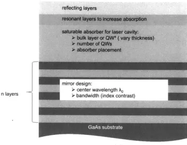
3.2 Semiconductor-based Saturable Bragg Reflector Design Overview . . . . 65
3.2.1 Broadband mirrors . . . . 65
3.2.2 SBR Fabrication Process Overview . . . . 67
3.2.3 Large-scale oxidation for large-area SBRs . . . . 74
4 Wet Oxidation of AlAs for SBRs 79 4.1 Chem ical Process . . . . 79
4.2 Analytical M odel . . . . 82
4.2.1 First generation SBRs - 500 pm circular mesas . . . . 87
4.2.2 Second generation SBRs - Inverted structure mesas . . . . 91
4.2.3 Results: Rate Dependence on Oxidation Time . . . . 96
4.2.4 Results: Rate Dependence on Oxidation Temperature . . . . 98
4.2.5 Effect of Temperature Ramping on Oxidation Rate . . . . 102
4.2.6 Results: Rate Dependence on AlAs Layer Thickness . . . . 103
4.2.7 Results: Rate Dependence on Absorber Strain . . . . 109
4.2.8 Results: Rate Dependence on Geometry . . . . 111
4.2.9 Dependence on Aluminum Composition . . . . 119
4.2.10 Other investigated trends . . . . 119
4.2.11 Conclusion... . . . . . . . 120
5 Effects of Oxidation on SBRs 121 5.1 Oxidation-induced delamination. . . . . . . . . 121
5.1.1 Effect of oxidation temperature on delamination . . . . 122
5.1.2 Effect of AlAs layer thickness on delamination . . . . 126
5.2 Structural changes due to oxidation . . . . 130
5.2.1 Surface Texture Analysis . . . . 130
5.2.2 X-Ray Diffraction Analysis of absorber . . . . 132
5.3 Conclusion . . . . 134
6 Optical Characterization of Structures 135 6.1 Introduction . . . . . . . . 135 6.2 Large area broadband III/V saturable Bragg reflectors for Cr:LiSAF laser . 136
6.3 Large area broadband III/V saturable Bragg reflectors for Ti:Sapphire and Erbium-doped fiber laser . . . . 140
6.3.1 Non-Saturable loss measurements.... . . . . . . . . 146 6.4 Large area broadband III/V saturable Bragg reflectors for Cr:ZnSe laser . . 148 6.4.1 Hydroxyl absorption . . . . 149
6.5 Conclusions . . . . 153
6.6 Future Work... . . . . . . . . 155
A SBR Inventory 157
B SBR Oxidation Log 159
List of Figures
1-1 Band gap energy versus lattice constant of various III-V semiconductors demonstrating flexible band gap combinations (adopted from Tien, 1988). . 20 1-2 Real space representation of a 3D, 2D ID periodic structures. . . . . 21 2-1 Light-Matter interaction processes whereby Ec is the edge of the conduction
band and E, is the edge of the valence band. . . . . 26
2-2 A simplified depiction of the active region due to excitation. Shaded circles represent electrons or filled states while unshaded circles represent holes or em pty states [25]. . . . . 27 2-3 Density of states, g(E), for charge carriers in structures with different
dimen-sionalities [26]... . . . . . . . . . . ... 28
2-4 A schematic of QD energy levels with different built-in carrier distributions. The thermal smearing of the closely spaced hole energy levels requires that an excess of holes via p-type doping be built in so as to facilitate ground state recom bination [6] . . . . 30 2-5 Structure of VA96 semiconductor laser with epitaxial semiconductor layers
and the four quantum wells within the active region. . . . . 31
2-6 Room temperature photoluminescence spectrum for grown VA96 epilayers
showing an InGaAs emission peak at 1630nm. . . . . 32 2-7 Structure of VA117 QD semiconductor laser. The active region contains four
InAs DW ELL layers. . . . . 33
2-8 Room temperature photoluminescence spectrum for grown VA117 epilayers
2-9 BeamProp BPM simulations showing transverse mode confinement for 3pm-wide ridge at (a) 0.5pim and (b) 0.9pum etch depths. Lateral confinement increases with ridge depth . . . . 34 2-10 SEM micrographs showing smooth, nearly vertical resist sidewalls of positive
photoresist that defines the SiO 2 etch mask, which then defines the
semicon-ductor ridge waveguides in subsequent processing steps. . . . . 38
2-11 SEM micrographs showing the SiO2 etch mask, after the photoresist has been
completely removed... . . . . . . . . . 39
2-12 SEM micrographs of the ICP RIE etch with the Si0 2 etch mask still present.
The etch conditions were 0.6Pa chamber pressure, 150W ICP RF power, 100W Bias RF power, 0.5 sccm C12, 1.0 sccm SiCl4, 10 sccm Ar.
. . . .
412-13 (a) SEM micrograph showing BCB (cyclobezene) offering full planarization
of etched InP ridge waveguides. (b) BCB etch back using a 33% CF4, 67%
02 etch chemistry at a 15 mTorr and RF power of 148 W. Following a series of short etches that were accompanied by SEM inspections, the underlying
Si0 2 mask is revealed... . . . . . . . . . ... 42
2-14 SEM micrograph showing a fully front-side fabricated representative laser sample following SiO2 removal and metal patterning to define the 30/20/200nm
Ti/Pt/Au contact pads. . . . . 42
2-15 Schematic of the continuous wave (CW) or pulsed laser testing setup.. . .. . 45
2-16 (a) Light versus current (LI) room temperature measurements of VA96
4-layer QW lasers with lateral ridge width of 3 pm. Lasers are 2mm-long as cleaved bars operating under CW and pulsed operation at 10% duty cycle. Results show Ith of l1OmA and a slope efficiency of 0.03mW/mA. (b) The lasing exhibited emission at A, = 1655nm. . . . . 46
2-17 Amplified Spontaneous Emission from VA117, a 4-layer QD laser
struc-ture operating under CW at an injection current I=500 mA and cooled to
T=15'C. The 1mm-long as cleaved lasers had lateral cavity widths of 6tm,
12pm and 3 0pm... . . . . . . . . . 47
2-18 AFM image of uncapped InAs quantum dots grown on InGaAsP under the
3-1 Fabry-Perot Resonator . . . . 55 3-2 (a) Schematic setup of an actively mode-locked laser [66]. (b) Temporal
evolution of optical power and losses in an actively mode-locked laser. The modulator causes increased losses for the pulse wings, effectively shortening the pulses. As the pulse duration relative to the pulse period is typically much smaller than shown, the pulse-shortening effect of the modulator is usually very weak [67]. . . . . 56 3-3 (a) Schematic setup of a passively mode-locked laser [66]. (b) Temporal
evolution of optical power and losses in a passively mode-locked laser with a fast saturable absorber. The shorter the pulse becomes, the faster will be the loss modulation. The gain stays approximately constant, as gain saturation is w eak [67]. . . . . . . . . 58
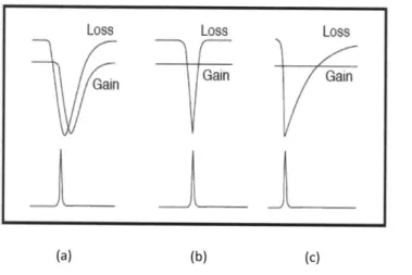
3-4 Pulse-shaping and stabilization mechanisms owing to gain and loss dynamics in passively mode-locked lasers: (a) using only a fast saturable absorber;
(b) using a combination of gain and loss saturation; (c) using a saturable
absorber with a finite relaxation time and soliton formation [67]. . . . . 59 3-5 Band gap energy and lattice constants of various III-V semiconductors at
room temperature [adapted from www.ulp.ethz.ch]. . . . . 61 3-6 Time-averaged reflectivity of an SBR as a function of fluence [73]. . . . . . 62 3-7 Non-linear reflectivity change of a saturable absorber mirror due to absorber
bleaching with (a) CW intensity and (b) short pulses. Isat is saturation intensity, Esat is saturation fluence, I is the CW intensity and Ep is the pulse energy incident on the absorber [67]. . . . . 64
3-8 Schematic of a Saturable Bragg Reflector illustrating the cross section of the
structure. ... ... ... 66
3-9 Overview of the fabrication of saturable Bragg reflectors with the major
process steps. ... ... 68
3-10 Circular and inverted mesa layout . . . ... . . . . 69 3-11 Schematic showing the lateral oxidation of the low index AlAs layers to form
AlxOY using H20 vapor. . . . . 71
3-12 Schematic of oxidation setup showing sample location within furnace, the
3-13 Parabolic gas flow velocity profile... . . . . . . . . . ... 73
3-14 (a) DIC image of a AlAs/GaAs DBR stack fully oxidized at 4500 C for
5 hours with severe delamination shown to originate in (b) from the
ox-ide/semiconductor interface... . . . . . . . . 74
3-15 DIC image of a fully oxidized AlAs/GaAs DBR stack at 420' C for 5 hours
without delamination. . . . . 75 3-16 Fourier Transform Infrared (FTIR) spectroscopy measurement of a DBR that
is designed to be centered at A = 1.55pm showing reflectivities before and
after oxidation... . . . . . . . 76 3-17 Fourier Transform Infrared (FTIR) spectroscopy measurement of an oxidized
DBR centered at A = 2.5pm with the area of inspection going from the edge, middle and center of an oxidized mesa. A slight blue shifted reflectance spectrum is observed towards the edge of the mesa possibly due to oxidation, albeit marginal, of the high index GaAs layer. . . . . 77 3-18 DIC images of preliminary attempts at fully oxidizing inverted DBR
struc-tures oxidized at (a) 425'C for 12 hours and (b) 425'C for 16 hours. The oxidation depths were measured to be 90pm and 98pm respectively. .... 78
4-1 Cross-sectional TEM showing the dense amorphous interfacial layer at the
oxidation front [78]... . . . . . . . . ... 80
4-2 Evolution of the rate of formation of As203 relative to its reduction and loss
of As from the oxidized layer, leaving behind a porous A1203 from (a )linear
and (b) parabolic time: increasing the thickness of the interfacial As203 layer
[76]. ... . . . . . . 81
4-3 Cross-sectional schematic of the lateral oxidation of a single AlAs layer show-ing the inward progression of the oxide layer from the gas/oxide interface. The AlAs layer is sandwiched by GaAs layers. The structures in this work have 7.5 pairs of GaAs/AlAs whereby the AlAs layer thicknesses are a few hundreds of nanometers. . . . . 82
4-4 3D model of a circular SBR or DBR stack structures. The structures have been patterned using standard photolithographic and etching techniques. . 88
4-5 Model of oxidation of AlAs in a circular mesa configuration. p(r)=concentration of oxidant at r, p* is proportional to the partial pressure of the oxidant out-side gas/oxide interface. a=AlAs thickness and physical parameters: D, k, h dependent on the process temperature. r, is the radius of the mesa while R, is the position of the oxidation front... . . . . . . . 89
4-6 3-D model of inverted SBR or DBR stack structures. The inverted struc-tures comprise of micron-sized aperstruc-tures, which give the oxidants access to the AlAs layers. The apertures have been patterned using standard pho-tolithographic and etching techniques. . . . . 91
4-7 Model of oxidation of AlAs in a inverted mesa configuration. p(r)=concentration of oxidant at r, p* is proportional to the partial pressure of the oxidant out-side gas/oxide interface. a=AlAs thickness and physical parameters: D, k, h dependent on the process temperature. r, is the radius of the aperture while
R, is the position of the oxidation front. . . . . 92
4-8 Vapor pressure of water as a function of temperature. . . . . 94 4-9 Depth of oxidation as a function of time for inverted mesa structure. .... 95
4-10 The oxidation rate as a function of the position of the oxidation front during the initial stages of oxidation at 450 C in r, = 250pm circular mesa struc-tures. [Inset: a partially oxidized mesa.] The model uses the same physical parameters as in Section 4.2.1. A rapid decrease of oxidation rate is indicated as the oxide front progresses inward. . . . . 97
4-11 The oxidation rate as a function of the position of the oxidation front for the full length 250pm oxidation at 450 C in r, = 250pm circular mesa struc-tures. [Inset: a partially oxidized mesa.] The model uses the same physical parameters as in Section 4.2.1. . . . . 98
4-12 Top-view DIC microscope image of partially to completely oxidized circular mesas, showing high index contrast between the unoxidized and the unox-idized regions. Each oxidation was carried out at 425 C, at a water bath temperature of 80-85'C and an N2flow rate of 2.2 L/min. . . . . 99
4-13 Dependence of the oxidation rate on the position of the oxidation front in circular mesa structures. [Inset: a partially oxidized mesa.] The theoretical curves are calculated from Equation 4.17. Rate parameters D, h, k, A and B are calculated at 400'C, 425'C and 450'C . . . . 100
4-14 Dependence of oxidation depth on oxidation time in circular mesa struc-tures. Theoretical curves are calculated from Equation 4.24. Rate parame-ters D, h, k, A and B are calculated at 350'C, 4000C, 425'C and 450'C. . . 101
4-15 Dependence of oxidation depth on oxidation time in circular mesa struc-tures. Theoretical curves are calculated from Equation 4.24. Rate parame-ters D, h, k, A and B are calculated at 420'C, 422.50C, 425'C and 435'C. . 102 4-16 A and B rate parameters calculated from Equation 4.21,4.22 adjusted for the
initial and final temperature ramps. Temperature is ramped up over 1.5 hrs from 1000C to the set point of 450'C and then back to 1000C . . . . 103
4-17 Dependence of oxidation depth on the oxidation time in circular mesa struc-tures. Each experimental point corresponds to an individually oxidized sam-ple. Theoretical curves are calculated from Equation 4.24, whereby a = 240nm. 104 4-18 A diagram of GaAs/AlAs interfaces at the oxidation front. By approximating
the front as a semi-circle with a contact angle, a-, an exponentially decreasing relationship exp(- 0/) on AlAs thickness, 0 exists [89]. . . . . 105
4-19 A SEM image showing the curved oxidation fronts in a partially oxidized Bragg stack. The delamination at the already weak GaAs/ Al203 interface
is a result of the SEM cleave. . . . . 106
4-20 Oxidation rate as a function of the position of the oxidation front in circular mesa structures. Rate parameters D, h, k, A and B are calculated at 450"C. An appreciable decrease in the oxidation rate is observed for AlAs layer thicknesses ranging from a = 450nm, 240nm to 150nm . . . . 107
4-21 Dependence of the depth of oxidation on time for AlAs layers of different thicknesses. Layer dependence is investigated in both (a) DBR and (b) SBR
4-22 Dependence of the depth of oxidation on time for AlAs layers of different thicknesses. The lines represent the theoretical calculations and the points represent the experimental data. Theoretical curves are calculated from Sec-tion 4.2.1. Rate constants at 420'C and 450'C were calculated for AlAs layer thickness a=240nm and a=450nm. . . . . 108
4-23 Optical microscope images of 2.4pm (a) DBR and (b) SBR structures in the inverted configuration. The SBR structure in (b) comprises of a defect-dense absorber that is grown on top of the DBR structure in (a). Both samples were oxidized simultaneously at 420'C for 2 hours. . . . . 109
4-24 Dependence of oxidation depth on oxidation time, influenced by the presence of an absorber section. The lines represent the theoretical calculations from Equation 4.26 and the points represent the experimental data. Rate constants at 420'C and 450'C were used to calculate the time profiles for AlAs layer thicknesses of (a) 240 nm- and (b) 450nm. . . . . 110
4-25 Layout of a unit cell of the mask used to explore the effects of feature geome-try on the rate of oxidation. The feature geometries included circles, squares, rectangles and inverted structures... . . . ... 111
4-26 Schematics of thermal oxidation of AlAs. (Left) Top view lateral oxidation in a circular mesa configuration. (Right) Cross-sectional view in a straight
mesa configuration... . . . . . . . . . . . . . 113
4-27 Influence of the geometry of the mesa structure on the normalized oxide depth do/do(R-+ oc) versus the inverse of the radius of the mesa structure 1/R. the picture in the lower right corner shows two structures of different geometry oxidized together at 420 C for 4 hours. . . . . 114 4-28 The comparison of the oxidation depth as a function of oxidation time in
square and mesas. Acceleration of the oxidation rate is seen for the case of
the mesas... . ... ... .. .. .114
4-29 Schematics of thermal oxidation of AlAs. (Left) Top view lateral oxidation in a inverted mesa configuration. (Right) Cross-sectional view in a straight m esa configuration. . . . . 115
4-30 The comparison of the oxidation depth as a function of oxidation time in square versus inverted mesa structures. A faster deceleration of the oxidation rate is observed in the case' of inverted mesas. AlAs layer thickness a = 450nm. 116 4-31 The comparison of the oxidation depth as a function of oxidation time in
square versus inverted mesa structures. A faster deceleration of the oxidation rate is observed in the case of inverted mesas. AlAs layer thickness a = 240nm. 117 4-32 Oxidation rate profiles in circular and inverted structures. The dashed lines
correspond to full oxidation. Plan-views of a 7 pair GaAs(115nm)/AlOy(221nm) Bragg structure showing a 500 pm circular SBR as well as an inverted SBR with 150 pm center-to-center aperture spacing after complete oxidation. . . 118
5-1 SEM cross-section images showing delamination of an oxidized circular mesa
structures under sub-optimal oxidation conditions. In (b) two pairs of the Bragg layers have completely lifted off, leaving behind only 5 of the original
7 p airs. . . . . 122
5-2 SEM showing cross-section of an unoxidized Bragg stack. Cleave-induced
interfacial delamination is observed in (b) at the noticeably rougher GaAs
(top)/AlAs (bottom) interfaces... . . . . . . . . . 123
5-3 Temperature profile of the oxidation furnace showing a uniform central
heat-ing zone of -1.5 inches. . . . . 124 5-4 Optical microscope images looking down at the top surfaces of partially
oxi-dized circular mesas that were oxioxi-dized at 420 C for 2 hours. The thickness of the AlAs layers is 240nm . . . . 124
5-5 Optical microscope images looking down at the top surfaces of partially
oxi-dized circular mesas that were oxioxi-dized at 420 C for 5 hours. The thickness of the AlAs layers is 240nm . . . . 125 5-6 Optical microscope images looking down at the top surfaces of partially
ox-idized circular mesas that were oxox-idized for 5 hours. The thickness of the AlAs layers is 240nm. The oxidation temperature is (a) 438'C, (b) 4250C
5-7 Optical microscope images looking down at the top surfaces of partially
ox-idized circular mesas that were oxox-idized for 5.5 hours. The thickness of the AlAs layers is 240nm. The oxidation temperature is (a) 430'C and (b) 425'C. 127
5-8 Optical microscope images looking down at the top surfaces of partially
oxi-dized circular mesas that were oxioxi-dized at 420 C for 2 hours. The thickness of the AlAs layers is (a) 240nm and (b) 450nm. . . . . 127 5-9 Optical microscope images looking down at the top surfaces of partially
oxi-dized circular mesas that were oxioxi-dized at 420 C for 5 hours. The thickness of the AlAs layers is (a) 240nm and (b) 450nm. . . . . 128 5-10 Optical microscope images looking down at the top surfaces of inverted mesas
that were oxidized at 420 C for 2 hours. The thickness of the AlAs layers is 450nm. Sample (a) is a DBR, Sample (b) is an SBR with a 50nm InAs
absorber. ... ... ... 129
5-11 Optical microscope images looking down at the top surfaces of partially
oxi-dized circular mesas exposed to oxidation for 5.5 hours. The thickness of the AlAs layers is 450nm. The oxidation temperature is (a) 415 C and (b) 4100 C. 129
5-12 The measured rocking curve of sample VB119 before and after oxidation.
Before: The peak of InAs is observed on the left of the dominant GaAs substrate peak. After: The rocking curve of the sample after a standard oxidation at 420 C for 5 hours. There is no shift of the peak corresponding to the InAs absorber layer following the high temperature 'oxidation' process. 133
6-1 (a) Differential interference contrast images showing the plan-view of a 7 pair Al0.17Gao.83As (60nm)/ AlAs (150nm) structure after oxidation at 425'C for
8 hrs. (b) SEM image showing the SBR cross-section. . . . . 136 6-2 Reflectance measurements of the oxidized Al0.17Gao.83As (60nm)/ AlAs(150nm)
VA130 SBR mesas. . . . . 137 6-3 Schematic of the single-mode diode-pumped Cr:LiSAF laser system that was
used in femtosecond tuning experiments [91]. . . . . 138
6-4 Optical spectra from the tunable Cr:LiSAF laser. Broadband tuning over 105nm is achieved. Small signal and saturated reflectivity of the oxidized SBR are also shown [91]. . . . . 139
6-5 Variation of the measured output pulse width and pulse energy over the
demonstrated tuning range [91]. . . . . 139 6-6 (a) Differential interference contrast images showing the plan-view of a 7 pair
GaAs(115nm)/ AlAs (240nm) structure after oxidation at 415'C for 8 hrs.
(b) SEM image showing the SBR cross-section. . . . . 140
6-7 FTIR measurement of the partially oxidized circular mesa. The measurement
of the oxidized region was from the outer area of the circular mesa while the measurement of the unoxidized region was from the center of the mesa. . . 141
6-8 FTIR measurement of narrowband (VA86) versus broadband (VA176) SBR
for laser systems at 1550nm showing the broad bandwidth in the oxidized SBRs due to the increased index contrast of the Bragg mirror. . . . . 142
6-9 Schematic of the single-mode Erbium-doped fiber laser system that was used
in mode-locking experiments with the oxidized SBR VA176 A,=1550 nm. . 143
6-10 (a) Optical Spectrum Analyzer (OSA) trace of a mode-locked pulse centered
at A,=1555 nm with a 3-dB spectral bandwidth of 8.5 nm using the oxidized circular mesa SBRs from VA176. (b) Mode-locking is achieved at a repetition rate of 314 MHz... . . . . . . . . . 144
6-11 Theoretical and FTIR reflectivity plots of the circular and IMSBR devices
that are centered at A, = 1550 nm showing the broad reflection bandwidth
of the oxidized SBRs... . . . ... 145
6-12 (a) Optical Spectrum Analyzer (OSA) trace of a mode-locked pulse centered
at A,=1556 nm with a 3-dB spectral bandwidth of 7.5 nm using the oxidized inverted mesa SBRs from VA176. (b) Mode-locking is achieved at a repetition rate of 312 M H z. . . . . 145
6-13 Schematic of the setup used to quantify non-saturable losses in oxidized
SBRs. The three-part experiment utilized a 1550 nm OPO emitting a steady stream of 150-fs pulses at a repetition rate of 80 MHz. . . . . 147 6-14 Representative reflectance traces from a circular mesa of VA176 as the fluence
is increased at four positions. Estimates of the percentage noise error are added onto the data. A non-saturable loss of ~ 2.5% is recorded 9.5mm away from the focussing lens... . . . . . . . . 148
6-15 Differential interference contrast images showing the plan-view of a 7 pair
GaAs(181nm)/ AlAs (410nm) structure in the inverted geometry (150tm center-center spacing) after full oxidation at 425 C for 8 hrs. SEM images showing the SBR cross-section also indicate complete exposure of oxidizing AlAs layers and complete oxidation. . . . . 149
6-16 FTIR measurement of the partially oxidized rectangular mesa. The
measure-ment of the oxidized region was from the outer area of the rectangular mesa while the measurement of the unoxidized region was from the center of the
mesa. ... ... ... 150
6-17 FTIR measurement of narrowband (VA172) versus broadband (VB123) SBR
for laser systems at 1550 nm showing the broad bandwidth in the oxidized SBRs due to the increased index contrast of the Bragg mirror. . . . . 150 6-18 Schematic of the Cr:ZnSe laser system that is pumped by a Thallium-doped
fiber laser that was used in mode-locking experiments with the oxidized SBR (VB123) A,=2450 nm ROC=reflective optical chopper, OC=output coupler
[92]... . . . . . . . . 151 6-19 FTIR spectra from VA175 DBR (184nm GaAs/450nm AlAs) that was
oxi-dized at 420 C for 2 hrs, followed immediately by a 10-min and a 60-min N2
anneal at 420'C. ... ... 152
6-20 FTIR spectra from VA175 DBRs (184nm GaAs/450nm AlAs)x7 oxidized
using dry oxidation at 725'C for 5 hrs and wet oxidation at 420'C for 2 hrs, followed immediately by a 30-min N2 anneal at 7250 . . . . 153
6-21 FTIR measurements of VA175 DBR (184nm GaAs/450nm AlAs)x7 wet
ox-ides taken 30 mins, 1 day, 3 days, 4 days and 5 days after oxidation at 420 C for 2 hrs followed by a 10min N2 anneal at 420'C. . . . . 154
Chapter 1
Introduction
1.1
Integrated Photonic Devices
Photonics is a field of engineering that deals with the manipulation for light for useful ap-plications, much as electronics do with electrons. The spectral range of interest in optics is usually between 100nm and 10pm [1, 2], which is the ultraviolet to infrared wavelength range, however the primary interest for photonic applications lies in an even narrower wave-length range spanning from the visible to near infrared ranges (Figure 1-1). Fortunately, this spectral range is largely aligned with and determined by the properties of materials used to make photonic devices. In this spectral range, the quantum energies of photons coincide with the band gaps of most semiconductors. The energy of a photon is critical because it determines the behavior of an optical wave in a semiconductor photonic device.
The uniqueness of photonic devices is that both wave and quantum characteristics of light are considered for the function of these devices. Generally, the particle (photon) nature of light dictates the operation of devices for emission, amplification or detection of light, while the wave nature is important for all operations and functions, but particularly so for modulation, switching and transmission of light. This thesis focuses on research on two kinds of photonic devices; 1) semiconductor lasers and 2) ID Saturable Bragg Reflectors.
The advancement of microelectronic fabrication techniques have enabled the develop-ment of semiconductor lasers. The lasers have gained special importance in the opto-electronics arenas [3] due to their compactness, the possibility of fabricating several indi-vidual lasers on a planar substrate, as well as in the field of integrated photonics due to the possibility of integrating lasers on a chip containing other photonic devices [4]. In this
--OAIP 2.0 vN
~
.- . AISbAISb 1.6 -> _MAs GaAs E lnP 1.0 1.2 -412 1.5 0.8 GaSb InAs 0.4 Ins4.0 6.0 0.0 5. .7I 5..8 7 LInSb 5.4 5.5 56 57 .8 5.9 6.0 6.1 6.2 6.3 6.4 6.5 Lattice constant U() (Angstroms)Figure 1-1: Band gap energy versus lattice constant of various Ill-V semiconductors demon-strating flexible band gap combinations (adopted from Tien, 1988).
thesis, quantum well and quantum dot heterostructure lasers have been fabricated with the purpose of characterizing the gain region for implementation in an all-optical logic chip. Semiconductor lasers using quantum-dots in their active regions have been reported to ex-hibit significant performance advantages over their bulk semiconductor and quantum-well counterparts namely: low threshold current, high differential gain and highly temperature stable light-current characteristics [5, 6, 7]. The lasing characteristics of a ridge-waveguide laser containing multiple layers of quantum wells and quantum dots as the active region are investigated.
The second photonic device category explored in this thesis is the Saturable Bragg Reflector (SBR), also referred to as SESAM. Something interesting happens when light propagates through periodic media, more technically referred to as photonic crystals. A photonic crystal is a 2D or 3D periodic structure whose dielectric constant and therefore its index of refraction is modulated periodically on the order of the wavelength of light within the photonic crystal. This periodic arrangement of high and low-index materials, leading to a substantial index contrasts, giving rise to a photonic band gap, an energy range that separates allowed and forbidden energy states. This energy separation is analogous to the
band gap for electrons that is observed in a semiconductor crystal. In 1887, Lord Rayleigh first demonstrated a one-dimensional photonic band gap from "laminated media", in which a spectral range of high reflectivity was observed [8]. However, it wasn't until Yablonovitch and John [9, 10] published their milestone work on 2D and 3D photonic crystals in 1987 that research in photonic crystals really began to take off. Great achievements have also been made in extending the ideas of ID laminated mirrors since Rayleighs time, including the work presented in this thesis. In the literature, photonic crystals are classified as one-dimensional (iD)', two-one-dimensional (2D), or three-one-dimensional (3D) as depicted in Figure 1-2. Each configuration offers attractive applications in optoelectronic devices such as micro-cavity waveguides [12], splitters [13], light emitting diodes (LEDs) [14], switches [15] and couplers [16]. The research presented in this thesis focuses on the development of large area Saturable Bragg Reflectors (SBRs), which use a ID photonic crystal to reflect a very broad spectrum of light for ultra-short pulse generation.
3D
2D
ID
Figure 1-2: Real space representation of a 3D, 2D ID periodic structures.
1.2
Scope of this thesis
After providing a general background on photonic devices in Chapter 1, Chapter 2 explores the use of 3D and 2D quantum confinement of charge carriers within quantum dots (QD) and quantum wells (QW) lasers respectively. The index-guided QD and QW heterostructure lasers that were fabricated in this work investigate the electrical and optical properties of the active regions for implementation in more complicated photonic devices. The various
'A misnomer in the optical community [11].
steps involved in the design, fabrication and characterization of these lasers are presented in detail.
A hard turn is made in Chapter 3, which focuses on the motivation for creating
ultra-short pulses on the order of picoseconds to femtoseconds (10-12 to 10-15 seconds). The theory behind the use of Saturable Bragg Reflectors (SBRs) for the generation of ultra-short pulses in various laser systems is presented. The design and fabrication of the III-V material based SBRs comprising of periodic layers whose thicknesses correspond to the wavelengths of the laser systems that are to be mode-locked is discussed.
The fabrication process that is central to the development of widely tunable broadband SBRs is described in greater detail in Chapter 4. A full discussion on the chemistry of the oxidation process that converts semiconductor Aluminum Arsenide (AlAs) to oxide is included. A physical model describing the lateral oxidation of AlAs using steam is presented in detail. The model takes into account several processing parameters in one equation and, therefore, can be easily applied to the process control of device fabrication. The relevant control parameters in the device modeling and fabrication include oxidation temperature, oxidation time, AlAs layer thickness, mesa geometry and the presence of strain/stress fields. Theoretical calculations are shown to agree well with measured experimental values.
One of the challenges associated with the fabrication of broadband SBRs is the tendency for layers to suffer structural damage during the high temperature oxidation process. In Chapter 5, an investigation of the structural changes induced by the oxidation process are investigated. Discussions of some of these challenges, as well as solutions, are presented.
Finally in Chapter 6, the thesis is summarized and concluded by presenting results from optical characterization and mode-locking implementation of fully-fabricated SBR devices. The benefits of using the large area broadband SBRs compared to conventional narrowband SBRs in real world ultrafast lasers are highlighted.
Chapter 2
Integrated Fabry-Perot Lasers for
Integrated Optical logic
2.1
Motivation
Today, long-distance internet traffic is transmitted optically. One of the key bottlenecks preventing increased data speeds remains the switching technologies that manage and direct network traffic. After hundred kilometers, the optical signal experiences losses and disper-sion and must be 3R regenerated (re-amplified, reshaped, retimed) and routed. The signal processing that is required for retiming, routing and regeneration is performed in the elec-tronic domain, requiring expensive optical-to-elecelec-tronic-to-optical (OEO) conversions. All-optical switching, which could eliminate these OEO bottlenecks, thereby delivering channels rates in the excess of 100 Gb/s [17], depends critically on the advancement of technologies in the photonic realm that are analogous to current electronic logic elements such as electronic transistors, buffers and amplifiers. Besides increased date speeds, power consumption can be greatly reduced by using optical switches, some groups reporting powers as low as 2 pJ per bit [18]. One of the enabling technologies that is involved in elementary optical logic units in the asymmetric twin-waveguide semiconductor optical amplifier (ATG-SOA), which enables optical circuits to be manufactured with both the active and the passive compo-nents using only one epitaxial growth. Quantum dot semiconductor optical amplifiers have already been realized [19, 20, 21] and integrated into optical logic structures. The fast car-rier dynamics could enable ultrafast operation in excess of 200 GHz [22] and extremely fast
gain recovery of ~130 fs [23]. Most of this ultra-fast work has been carried out at 1300 nm. Transitioning to 1550 nm is not trivial as a change in the substrate material from GaAs to InP. At this time, the lower lattice mismatched InAs quantum dots on inP as are not as well-developed as inAs quantum dots on GaAs. The motivation for this work was to characterize the active regions of various heterostructure lasers for the incorporation of the active regions into integrated optical logic chips, with the ultimate goal of developing an all-optical chip that are suitable for optical networks.
Semiconductor heterostructure lasers utilize the band gap differences of various avail-able semiconductor materials. The band gap refers to the energy difference (in electron volts(eV)) between the top of the valence band and the bottom of the conduction band in the semiconductor. A layer of low band gap material is sandwiched between two high band gap layers such that each of the junctions between different band gap materials is called a heterostructure. The lasers that are fabricated in this work offered a means of characterizing the active region-the smallest band gap region where free electrons and holes exist simultaneously and radiatively recombine. Holes are missing electrons. They behave as particles with the same electric properties as the electrons would have occupying the same states except that they carry a positive charge and effective mass. If the active region layer is made thin enough, it becomes a quantum well, which confines charge carriers, which were originally free to move in three dimensions, to two dimensions. A quantum well laser diode not only makes much shorter wavelengths accessible since the wavelength of the light emitted by a quantum well laser is determined by the width of the active region rather than just the band gap of the material from which it is constructed. Additionally, the efficiency of a quantum well laser is also greater than a conventional bulk semiconductor laser diode due to the stepwise form of its density of states function- the function that describes the number of states per interval of energy at each energy level that are available to be oc-cupied by charge carriers. If the idea of quantization is extended even further, quantum dots can be created, whereby charge carriers are confined in all three spatial dimensions. The electronic properties of quantum dots are closely related to the size, shape and com-position of the individual dot. For example, the smaller the dot, the larger the band gap, therefore more energy is needed to excite the dot-elevate an electron from the valence band to the conduction band, and concurrently, more energy is released when the dot returns to its resting state. Furthermore, the spatial confinement and the delta-like nature of the
electronic density of states in quantum dot lasers results in more efficient devices operating at lower threshold currents; the minimum current needed to sustain laser action in a laser diode. The lasers presented in this section utilize quantum well (QW) as well as quantum dots (QD) active regions and are characterized for eventual incorporation into Optical logic gates; devices that performs Boolean logic operation on one or more logical inputs and produces a single logical output, all in the optical realm [24].
2.2
Heterostructure semiconductor laser basics
Semiconductor lasers emitting at telecommunication wavelengths (1.3 pm -1.6 Pm) have been developed from compounds composed of Column III and Column V elements because these compound semiconductors have band gap energies that cover this wavelength range and well beyond. For example, band gaps in direct semiconductors, in which the momentum of electrons and holes is the same in both the conduction band and the valence band, ranges from 0.5 eV - 4 eV, which in wavelength corresponds to 2.48 pm - 0.31 pum respectively. A laser accomplishes light amplification via the radiative recombination of excited charge
carriers i.e. electrons that have been elevated from the valence band to the conduction band, leaving behind holes in the valence band. In the presence of positive optical feedback the radiation field is reinforced, resulting in lasing. The active region can either be optically-pumped or electrically-activated and may emit light through spontaneous or stimulated emission processes. The active region can also absorb quanta of light energy referred to as photons via stimulated absorption. These light-matter interaction process are depicted in Figure 2-1.
Excited carriers will normally release their excess energy in the form of incoherent radi-ation and, in so doing, revert back to a stable state via the process of spontaneous emission. Alternatively, in the presence of radiation, a photon can possibly interact with an excited carrier while that carrier is still in its high-energy state. The carrier may then release its excess energy in the form of a photon that is in phase with, has the polarization of, and propagating in the same direction, as the stimulating photon in a process called stimulated emission. These emitted in-phase photons bounce back and forth inside the resonator cavity that is created by the parallel end facets of the semiconductor. Subsequent reflections from the ends of the cavity, which includes the active medium results in an increase in the number
Spontaneous Emission Stimulated Absorption Stimulated Emission
Before After Before After Before After
F, E Ec 9 EV e E = electron = hole \vom+= photon
Figure 2-1: Light-Matter interaction processes whereby Ec is the edge of the conduction band and E, is the edge of the valence band.
of photons and consequently a gain in the intensity of emission with every pass. This optical feedback is usually achieved by placing high reflective coatings or by having well-cleaved mirror-like facets, which utilize Fresnel reflection at the semiconductor/air interfaces.
In accordance to Fermi-Dirac statistics, most carriers are ordinarily in their lowest energy state. In order to achieve lasing, the number of electrons in the conduction band must exceed a threshold value so that the probability of emission is higher than absorption. A population inversion [25] in which most carriers are excited to higher energy states, must be created and maintained so that stimulated emission dominates spontaneous emission and absorption processes, which occur concurrently. Pumping by electrical or optical means leads to a band structure depicted in Figure 2-2 in which more energy is required for absorption than for emission so that the material exhibits a net gain of radiation.
The idea to exploit quantum effects in heterostructure semiconductor lasers to produce wavelength tunability and to achieve lower threshold current densities by reducing the number of translational degrees of freedom of the carriers and thus changing the density of states at the band edges was first proposed by Dingle and Henry in 1976 [5]. Quantum wells became widely explored by the late 70s, but carrier confinement existed in only one direction and so the need for improvement was clear. Towards the turn of the 2 1st century,
Figure 2-2: A simplified depiction of the active region due to excitation. Shaded circles represent electrons or filled states while unshaded circles represent holes or empty states
[25].
lasers using confinement in two directions; quantum wires or quantum dashes and all three directions; quantum dots began to gain physical realization.
Quantum dot (QD) heterostructure lasers are a type of semiconductor laser that use quantum dots as their active media. Quantum dots are semiconductor nanocrystals of narrow band-gap material that are embedded in a wider band-gap material. Due to the strong 3D carrier confinement, devices that employ quantum dots have unique capabilities that are otherwise practically unachievable with bulk semiconductors or even with 2D-confined quantum wells. These advantages have to do with the fact that with additional restriction of electron motion comes the discretization of the allowed wave functions with distinct indices along the confining direction(s). These previously unavailable wave functions result in a modification of the energy spectrum, which in turn changes the nature of the density of states, as illustrated in Figure 2-3.
In particular, in a QD, the density of energy states, g(E), takes on the form of delta functions with peaks centered at atomic-like energy levels. This delta function density of states modifies the carrier distribution in such a manner as to enhance the concentration of charge carriers at the ground state at the expense of higher energy parasitic levels. In theory, when QDs are used as the active region of electrically-activated semiconductor lasers, the vast majority of the injected non-equilibrium carriers are expected to relax into
2D 1D (Quantum Well) (Quantum Wire)
OD
(Quantmun Dot)
Figure 2-3: Density of states, g(E), for charge carriers in structures with different dimen-sionalities [26].
a narrow energy range near the bottom the conduction band in the case of electrons and near the top of the valence band, in the case of holes. The fact that the majority of the electrons and holes are located in the ground state energy levels of the conduction and valence bands respectively facilitates ground-state recombination, thus enhancing material gain for ground state emission. In reality however, this ideal situation is limited by a finite carrier capture time. There is a possibility of non-radiative recombination occurring within the barrier quantum well layers in which the quantum dots dwell before the carriers have the chance to thermally relax into the ground state the quantum dot. In other words, the electronic transition of carriers from the barrier quantum well to the quantum dot occurs at a finite rate. This finite rate dampens the radiative recombination current through the active region, ultimately limiting the output power from the laser [271. As mentioned before, one of the direct results of the reduction in the carriers' translational degrees of freedom is in achieving lower threshold current densities, the injection current density above which light emission by stimulated emission dominates.
Another important functional benefit of the discretization of energy states is that it reduces the influence of temperature on device performance. The spacing of the energy subbands in QDs is on the order of 100 of meVs while the average thermal energy of carriers at room temperature is only 10's of meVs, an order of magnitude smaller. As such, the threshold current density in QD lasers should be unaffected by temperature up to about
3D (bulk)
300K [28] since the carriers can only be thermally excited to a very limited range within these sparsely-spaced energy levels.
QD
lasers are being developed for longer wavelength and higher power applications. Herman et. al [29] have shown that the gain from a single layer of QDs is sometimes insufficient in overcoming internal optical mode losses within a cavity. This is especially true for short cavities on the order of hundreds of microns in which the deposition of high reflectivity coatings on the output facets presents fabrication challenges. Growth of multi-stack QD layers has been developed to enhance modal gain in short cavity QD lasers[30]. In order for the formation of identical stacked structures, a smooth spacer layer between each QD layer is crucial so as to form QDs with uniform characteristics because even the slightest departure from uniformity would cause inhomogeneous broadening due to strain alteration. The purpose of the spacer layer is to counteract the strain fields from the buried dots and can be thought of as a means of resetting the lattice structure in preparation for growth of another quantum dot layer.Despite all of these developments, published results failed to indicate any significant speed performance increases over planar QW lasers until the idea of doping QDs with holes was proposed and implemented. Deppe et. al have shown that for deep confinement poten-tials as in GaAs-based 1300nm lasers, p-type doping in conjunction with the intrinsically high carrier density associated with QDs is very effective in enhancing the gain character-istics so as to produce modulation response speeds in excess of 30 GHz [6]. Figure 2-4 illustrates the relevance of the energy spacings of electron and hole energy levels [6].
Whereas the energy spacing for electrons is ~70meV, meaning that the electrons have a high probability of being confined to the ground state, the spacing for holes is -10meV, which causes a thermal smearing of hole population among hole states. Thermal hole broadening had been shown to suppress gain performance [31]. Figure 2-4 illustrates that in the undoped QD layer case, charge neutrality requires an increase in the number of electrons that must be injected so as to achieve population inversion. As a result, the injected radiative current must be increased and hence the differential gain is decreased [6].
If an excess of electrons is built in, as in the n-type doped case, the problem is made even
worse because the injected holes that are thermally smeared among excited states recombine with the excess electrons in the higher energy states. If instead the hole density is increased as in the p-type doping case, the large built-in hole concentration ensures that there will
undoped n - doped p - doped
Ee, oE
me,mh 0,0 0.964 eV
Eh, AEh
Figure 2-4: A schematic of QD energy levels with different built-in carrier distributions. The thermal smearing of the closely spaced hole energy levels requires that an excess of holes via p-type doping be built in so as to facilitate ground state recombination [6]
be enough holes in the ground level of the valence band with which injected ground state electrons can radiatively recombine. As a result of p-type doping, room temperature ground state optical gain, as well as differential gain, can be increased.
Self-assembled quantum dots reside in the quantum well in what is called the "dots-in-a-well" (DWELL) design [32] in which lattice-mismatched quantum dots such as InAs are deposited in a InGaAlAs quantum well that is in turn placed in a wider band-gap InGaAsP matrix. As mentioned in the motivation of this work, the size of the QDs determines the energy band gap and consequently the emission wavelength. Precise and narrow emission wavelength tuning is not trivial because the self-assembled nature of growth of QDs results in a QD size distribution, thereby leading to a smearing of energy levels and consequently
a broadening of the emission spectral width.
2.3
Simulations
The primary theme in considering laser design is how electrical and optical confinement are to be achieved. The most commonly fabricated semiconductor lasers are either gain-guided or index-guided whereby the difference is in the lateral confinement of the injected carriers
and consequently, the optical mode in the active region.
In stripe-geometry, gain-guided lasers, the top metal contact is defined by fabrication processes. Injected carriers spread along the lateral direction due to lateral carrier diffusion
and current spreading and as a result, the effective width of the carrier distribution, n, and the optical gain profile end up being wider than the actual metal contact width. The gain distribution is the mechanism behind the confinement of the optical mode in the lateral direction. Lateral carrier spreading also degrades the laser performance by increasing the threshold current and therefore reducing the quantum efficiency. In contrast, for index-guided lasers, such as the ridge waveguides lasers in this work, the lateral confinement of injected carriers and consequently the optical mode, are achieved by the use of a low-index dielectric. The low-low-index dielectric enhances the contrast in the lateral effective low-index profile, thereby confining the optical mode in the high-index region.
A schematic of an as-grown Quantum well laser structures (VA96) that was grown in
this work is shown in Figure 2-5. The use of a separate confinement heterostructure enables electrical confinement while optical confinement is achieved by means of ridge waveguides that are fabricated in subsequent processing.
F
_
50nm inO.5GaO.4,As:Be (5E19)700nm InP:Be (1E19) 200nm 1n,,Ga.,As..P.
XA
180nm in0 Gam1AsaM2Pam 500nm InP:Si (3E18)
Figure 2-5: Structure of VA96 semiconductor laser with epitaxial semiconductor layers and the four quantum wells within the active region.
The active region of the VA96 epitaxial structure that is shown in Figure 2-5 comprises of four InGaAs quantum wells separated by InGaAsP cladding layers. The active region is sandwiched by undoped InGaAsP inner cladding layers followed by InP outer cladding layers that are lightly doped with Be and Si for the p-type and n-type regions respectively. Holes are injected into the laser through the top p-type InGaAs:Be layer while electrons are
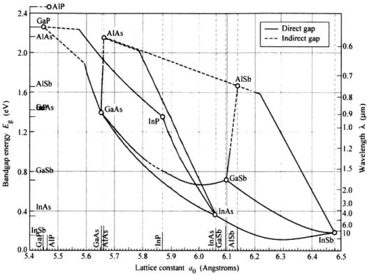


![Figure 3-5: Band gap energy and lattice constants of various III-V semiconductors at room temperature [adapted from www.ulp.ethz.ch].](https://thumb-eu.123doks.com/thumbv2/123doknet/14733733.573650/61.918.216.700.191.895/figure-energy-lattice-constants-various-semiconductors-temperature-adapted.webp)
![Figure 3-6: Time-averaged reflectivity of an SBR as a function of fluence [73].](https://thumb-eu.123doks.com/thumbv2/123doknet/14733733.573650/62.918.236.640.388.674/figure-time-averaged-reflectivity-sbr-function-fluence.webp)