HAL Id: cea-02421894
https://hal-cea.archives-ouvertes.fr/cea-02421894
Submitted on 20 Dec 2019HAL is a multi-disciplinary open access archive for the deposit and dissemination of sci-entific research documents, whether they are pub-lished or not. The documents may come from teaching and research institutions in France or abroad, or from public or private research centers.
L’archive ouverte pluridisciplinaire HAL, est destinée au dépôt et à la diffusion de documents scientifiques de niveau recherche, publiés ou non, émanant des établissements d’enseignement et de recherche français ou étrangers, des laboratoires publics ou privés.
New calculation method for PWR control rod
assemblies with APOLLO3®
V. Jouault, J.-M. Palau, G. Rimpault
To cite this version:
V. Jouault, J.-M. Palau, G. Rimpault. New calculation method for PWR control rod assem-blies with APOLLO3®. Annals of Nuclear Energy, Elsevier Masson, 2017, 110, pp.282-289. �10.1016/j.anucene.2017.06.029�. �cea-02421894�
N
EWC
ALCULATION METHOD FORPWR
C
ONTROLR
ODA
SSEMBLIES WITHAPOLLO3
®V. Jouault, J.-M. Palau, G. Rimpault
CEA, DEN, DER/SPRC/LEPh, Cadarache, F-13108, Saint-Paul-lez-Durance, Contact: [email protected]
A
BSTRACTIn this paper, we present recent advances on PWR core calculations schemes with the most advanced features of the new deterministic neutronic transport code APOLLO3®. We focus mostly
on reactivity effects of control rod sub-assemblies representation. Two kinds of representation are being studied: a representation in which the control rod sub-assembly is surrounded by standard sub-assemblies, calculated using 2D TDT-MOC solver associated with the fine structure self-shielding method in 281 groups at the Lattice calculation level; and a semi-heterogeneous modeling (3x3 zones) of the control rod sub-assembly at the Core calculation level. Taking advantage of the possibility of subdividing a sub-assembly with the MINARET core solver which uses an unstructured conforming triangular spatial mesh (Discontinuous Galerkin Finite Elements), the core calculation represents much better the control rod shadowing effects within the control rod sub-assembly. Tests to demonstrate the ability of such a calculation scheme have been carried out on an UOX fueled PWR reactor, the Saint-Laurent B1 reactor. The accuracy of the new APOLLO3®
scheme has been tested against TRIPOLI-4® and has been found extremely accurate without
requiring any equivalency method. This calculation scheme lays down the foundations a new upgrading approach for deterministic calculations to study PWR cores.
Keywords: APOLLO3®, V&V, PWR, Control Rod
INTRODUCTION
In order to meet new industrial’s expectations in terms of neutronic calculation accuracy and versatility, CEA launched the APOLLO3® project [1]. The project main purpose is to develop the deterministic multi-purpose neutronic transport code APOLLO3®. This is being done at CEA with the support of EDF and AREVA, with the aim of having a better modeling of physical phenomenon of existing reactor cores (until 3rd generation) but also of future reactor concepts (4th generation). APOLLO3® is aiming at replacing the previous 2nd generation of deterministic codes like APOLLO2 [2], CRONOS2 [3] and ECCO/ERANOS [4].
The APOLLO3®-LWR package built with APOLLO3® solvers defines reference calculation schemes associated with a nuclear data library to calculate all neutronic parameters together with certified biases and uncertainties derived from the VV&UQ process. This VV&UQ process incorporates numerical verification and validation as well as experimental validation leading to uncertainty quantification. The purpose of this paper is to present the recent developments in the PWR calculation scheme of APOLLO3®, mostly focusing on the effect of control rod sub-assemblies representation on reactivity. After presenting how we perform the V&V processes, we will present the current APOLLO3® reference calculation scheme for PWR calculation. Then, the new control rod assemblies’ representation will be introduced and its benefits will be shown on an application case, the Saint Laurent B1 reactor core.
I.
APOLLO3
®V&V
PROCESSIn order to assess the quality (performance, reliability and flexibility) of the code, a rigorous Verification and Validation (V&V) methodology has been established. It is based on a two steps approach.
The first step is Verification. It consists in verifying that the numerical resolution of neutronic models and programming of each module is correct. This step should be exhaustive as much as possible and must cover the wide range of functionalities and applications cases. This verification also includes a dedicated “Test Machine” which verifies that tests on old versions remain valid in the new code versions (non regression tests).
The second step is the numerical Validation. It quantifies the accuracy of the neutronic models used in APOLLO3®. The APOLLO3® Validation covers the main functionalities of the code (self-shielding models, flux solvers, homogenization, condensation, depletion, kinetics, perturbation/sensitivity analysis) through a dedicated model based on the PIRT (Phenomena Identification and Ranking Table) methodology [5]. Generally, this validation is based on a comparison of APOLLO3® deterministic calculation against TRIPOLI-4® [6] continuous-energy Monte-Carlo reference calculation. Both calculations use the same nuclear data library (based on JEFF3.1 evaluation).
Despite technological improvements in computer science (number of operations per second and storage volume increased), approximations are unavoidable in deterministic codes. Yet, those approximations bring more or less important discrepancies on different core characteristics against reference calculations (for example Monte-Carlo). The V&V process is therefore the search of an optimum on these discrepancies between calculation time and accuracy. The innovation in the current validation process comes from the fact that each approximation existing in a solver is being validating independently, hence removing the possibility of having compensating errors.
II.
APOLLO3
®C
ALCULATIONS
CHEMEII.A. Principle of the standard two-steps Calculation Scheme
The use of a scientific calculation code to run a simulation requires, from the user, many choices among the calculation models and options of the code. Those choices should match design specification of different natures (grid, solver type …), consistently with physics phenomena. All those choices establish what we call a calculation scheme.
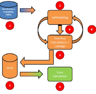
The typical calculation scheme for APOLLO3® is presented in Fig. 1. It is based on the separation of the cell/lattice calculation (orange) from the core calculation (green).
Fig. 1 : APOLLO3® calculation scheme
First, the code sets the nuclear data multi-group libraries, associated with probability tables, following the energy grid choice by the user (1). Then self-shielding calculations
(2) are performed to generate self-shielded cross sections of relevant resonant isotopes in
different regions. Those cross sections are used in the sub-assembly flux calculation (3), and this process repeats itself (4 and 4’) with eventually updating of fission and slowing-down sources (needed for FBR applications). By using ad-hoc leakage and homogenization/condensation models we get self-shielded, condensed and homogenized (5) cross sections which are stored in a Multi-Parametric Output library (MPO). Finally, we use the different MPOs (processed for each kind of sub-assembly) to launch the core calculation with appropriate flux solver (6).
II.B. PWR Calculation Scheme
The Table 1 presents the current APOLLO3® reference calculation scheme for PWR.
Table 1: APOLLO3®-LWR Calculation Scheme
Calculation Step Functionality Value
Lattice Calculation (2D)
Scattering Anisotropy (1) P3
Energy Grid (1) 281 Groups
Self-shielding (2)
Fine-structure method for the core
Sub-group method for the reflector Self-shielding solver (2) Multicell
Flux Solver (3) TDT-MOC
Core Calculation (3D)
Energy Grid (5) 20 Groups
Flux Solver (6) MINARET (SN) The 2D Lattice calculation scheme is based on the SHEM-MOC [7] reference calculation scheme of APOLLO2. The energy mesh is the optimized SHEM-281 groups, and the self-shielding calculation is performed with a fine-structure method (Livolant-Jeanpierre [8]), using a Pij multicell model and the Sub-Group method for the steel
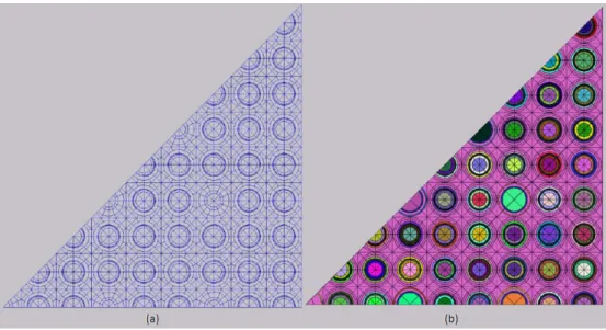
reflector. The flux solver is TDT-MOC [9], a solver which relies on the Method of Characteristics. The only difference between APOLLO3® and APOLLO2 calculation scheme is the spatial meshing of assemblies (cf Fig. 2). The reference scattering anisotropy is chosen as P3 Legendre polynomial expansion of scattering cross-sections, since results of a recent study [10] showed that a P3 order is enough to treat scattering anisotropy correctly.
Even though APOLLO3® is designed to be a multi-purpose code (i.e. treat any kind of reactor), we still need, at present, to have different types of calculation schemes depending on which type of reactor core we are dealing with. In the near future, the APOLLO3®-LWR calculation scheme will incorporate a 361 group energy grid, a sub-group method and an exact collision probability method as a self-shielding solver.
Fissile and control rod sub-assemblies are treated directly with this calculation scheme, in an infinite lattice representation. For steel/water reflectors, a different representation is needed, since there are no fissile isotopes in these media.
Fig. 2 : APOLLO2 (a) and APOLLO3® (b) spatial meshes for PWR 17x17 assemblies
To calculate axial reflectors self-shielded cross sections, we first do a calculation of a fissile sub-assembly and generate its homogenized (but not collapsed) cross sections. Then, we perform an axial traverse calculation with TDT-MOC on a half-assembly (top-half or bottom-half corresponding to top or bottom reflector) with the previously generated cross sections. We thus homogenize and collapse the resulting self-shielded cross sections of the reflector.
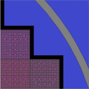
To calculate the radial reflector self-shielded cross sections, we represent a pattern including fissile sub-assemblies and an exact geometric description of the radial reflector (an example is provided in Fig. 3). The self-shielding is applied to the fissile sub-assembly and the reflector separately, the reflector self-shielded cross-sections being processed by using a traverse description at this step. Then, a TDT-MOC calculation is performed on the pattern (considered as an infinite lattice), and the self-shielded, homogenized and collapsed cross sections for the radial reflector are generated.
The core calculation is performed with MINARET [11], a SN core solver (i.e. the angular variable is treated with the Discrete Ordinates method). MINARET solves the
time-independent first-order form of the Boltzmann equation using the DGFEM method (Discontinuous Galerkin Finite Element Method) to treat the space variable. The spatial mesh is triangular and unstructured – but conform – in 2D and semi-unstructured in 3D (cylindrical).
Fig. 3 : Representation of the radial reflector for the Saint Laurent B1 reactor core
III.
C
ONTROLR
ODR
EPRESENTATIONThe treatment of sub-critical heterogeneous sub-assemblies presents important challenges for deterministic codes. Existing neutrons mostly come from the fissile zones and are transported through absorbers sub-assemblies. Since a straightforward one-step 3D core transport calculation isn’t possible yet, we need to define intermediate calculations with a reduce impact of approximations and well suited representations in order to produce relevant self-shielded cross sections for sub-critical media. More specifically, this may require the description of part of the core (several assemblies called clusters as we shall see further), in order to have an energy spectrum similar to the one established in the core.
This kind of representation has been used for axial and radial reflectors and we will investigate in the following section the performance of this model for control rod sub-assemblies.
III.A. Lattice Representation
In the present PWR reference calculation scheme, the calculation of the control rod sub-assembly is performed using the same model as fissile sub-assemblies, i.e. the infinite lattice model, based on the fundamental mode assumption (Isolated representation). However, this representation isn’t realistic when we consider the whole core heterogeneous geometry (in terms of different assembly types). It can be assessed that a new representation is necessary to describe more precisely physical phenomena occurring at whole core level.
In classical PWR reactor cores, control rods assemblies are surrounded by a lattice of fissile assemblies. This configuration permits to avoid power peaks and to smooth the power radial distribution.
In order to reproduce this configuration, we propose a new representation of control rods for
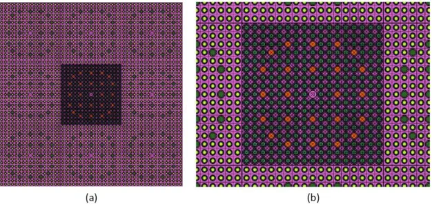
the lattice step of the calculation (cf. Fig. 4). The calculation is performed on a 3x3 cluster,
with one control rod sub-assembly surrounded by 8 fissile sub-assemblies. We use a refined spatial mesh on the central (rodded) sub-assembly, to have an accurate description of the local spatial phenomena in this assembly, but we don’t refine the surrounding fissile assemblies, since we don’t need to have a so high accuracy on the incoming spectrum (this would require a too high running time and a large memory demand for a poor accuracy gain in the end1).
The calculation is performed according to the reference calculation scheme (SHEM-MOC) recommendations in terms of fine structure self-shielding and TDT-MOC flux solver options [7]. The two kinds of sub-assemblies are self-shielded separately, with fine structure method and the multicell model, in an infinite lattice. Then, the TDT-MOC calculation is performed on the cluster, with specular reflective boundary conditions. Finally, the control rod is homogenized and we generate the homogenized collapsed self-shielded cross sections for the central zone.
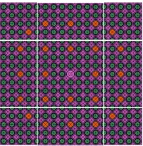
Fig. 4 : Cluster-type representation for PWR control rod calculation (a). The central part
corresponds to the control rod sub-assembly with a refine spatial mesh (b), and peripheral zones are fissile sub-assemblies.
III.B. Core Representation
In the reference calculation scheme, at the core calculation step, all assemblies are homogenized radially, and only axial heterogeneities are considered (depending on control-rod insertion). In the nominal configuration, this representation is acceptable since the fissile assemblies’ local effects have an insignificant impact on the core reactivity. However, in the rod inserted assembly configuration, that is not necessarily the case, especially with thermal/epithermal strong absorbers (B4C/AIC/Gd) control rod assemblies.
In classical PWR control rod assemblies, there are around twenty control rods. As you can see in Fig. 4b for example, those control rods are distributed regularly all over
1 In order to have an exact representation, each control rod environment (control rod near radial
the assembly. With this distribution, we can distinguish two regions: a central zone, delimited by the eight central control rods, and a peripheral one. Because of this division control rod shadowing (or screening) effects varying from the periphery to the central part occur.
When a neutron enters a control rod assembly, it has a great chance of being absorbed by the peripheral control rods. Only few neutrons pass through the peripheral zone and are absorbed by central control rods. Hence, central control rods “see” a different neutron spectrum than peripheral ones, in other words, central control rods are
shadowed by peripheral ones.
When control rod assemblies are homogenized, these phenomena aren’t taken into account in the core calculations. To fix this problem, we propose a partial homogenization of the control rod assemblies, which will consist on dividing them into nine regions, including the central zone as shown in Fig. 5.
Fig. 5 : Partial Homogenization of a control rod sub-assembly (control rods are in
orange).
IV.
PWR
C
OREC
ALCULATIONS WITHAPOLLO3
®IV.A. The Saint-Laurent B1 Reactor Core
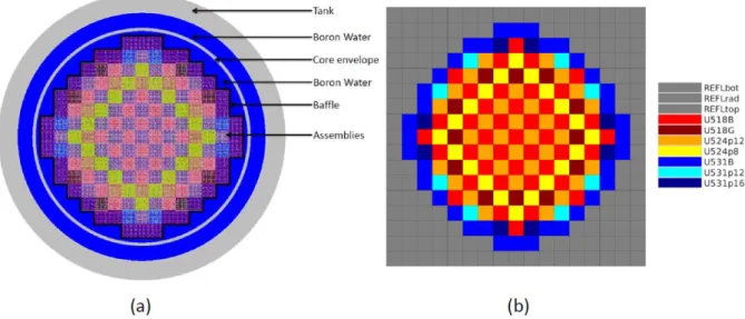
The Saint-Laurent nuclear power plant is located in France, near Orléans city in the Loire valley, France. The site includes two operating PWR (900 MWe) B1 and B2, which began operation in 1983. The Saint-Laurent B1 reactor core is represented in Fig.
6a.
In the SLB1 reactor core there are seven types of Uranium oxides fissile assemblies, differing by their enrichments, the number of Pyrex rods and the type of control rod (black or gray1). In total, there are three types of control rod assemblies, named U518B,
U518G and U531B. U518B and U518G are the same assemblies, but U518G contains gray
control rods, whereas U518B has black control rods.
1 Black control rods are only composed with Ag, In and Cd (AIC) whereas gray control rod also have
Fig. 6 : Saint-Laurent B1 reactor core, represented with TRIPOLI-4® (a) or
APOLLO3® (b)
The two steps lattice (2D)/core (3D) calculations are performed as follows: first, the self-shielded homogenized and collapsed cross sections are produced for each sub-assembly, with control rod inserted or withdrawn. Then, the core calculation is launched using the MINARET flux solver. The radial reflector is represented as a cartesian lattice of homogenized assemblies (cf. Fig. 6b) consistent with the cluster model used in the
lattice calculation (cf. Fig. 3).
The reference Monte-Carlo calculation is performed with TRIPOLI-4®, following 1 billion neutron histories and reaching a precision better than 4 pcm (1σ) on 𝒌∞.
Table 2 : Reactivity biases for SLB1 core calculations with reference calculation
scheme
Nominal Rod inserted TRIPOLI-4® 1.06740 0.90549
APOLLO3® 1.06848 0.89759
∆𝝆 (pcm) + 95 - 973
In the nominal configuration, the APOLLO3® reference calculation scheme is accurate against TRIPOLI-4®, even if there is still room for improvement. For example, we could replace the Fine Structure self-shielding method by the subgroup method on 361 energy groups, or use the MOC-3D [12] to generate axial reflectors’ cross sections.
In the rod inserted configuration, the bias isn’t satisfying and the reactivity is heavily underestimated by APOLLO3®. In order to seek the origin of this bias, we will use the bias decomposition.
IV.B. The bias decomposition method
The bias decomposition consists of dividing the global bias (resulting of the comparison of APOLLO3® and TRIPOLI-4®) into separate biases, all of which represent an approximation. This method requires the use of multi-group TRIPOLI-4®
calculations (instead of usual continuous ones), to which we give APOLLO3® lattice calculations resulting cross sections. This type of calculation will be noted T4 XS AP3.
In this part, we will consider two kinds of approximation for the core calculation: the flux solver and the impact of lattice approximations on core results. To evaluate the impact of flux solver, a comparison of calculations with identical self-shielded cross sections is required. Thus, the flux solver bias is determined by measuring the discrepancy between the APOLLO3® calculation and T4 XS AP31. On the other hand, to evaluate the impact of lattice approximations, a comparison with identical transport method is required. This bias is calculated by comparing the TRIPOLI-4® calculation with T4 XS AP3.
Table 3 : Bias decomposition of the SLB1 core for nominal and rod inserted
configurations.
Nominal Rod inserted Global bias (pcm) + 95 - 973 MINARET (pcm) + 2 - 75 Lattice Approximations (pcm) + 93 - 898
Lattice approximations are the major contributions of the global bias, with a weight higher than 90 %. This means that some sub-assemblies’ cross sections are poorly calculated. To determine which sub-assemblies are responsible, we can divide the lattice approximations bias into sub-assembly biases, corresponding to the contribution of each sub-assembly.
To do so, in the T4 XS AP3 calculation, we replace one homogenized sub-assembly (with AP3 cross sections) by a heterogeneous one, with its true material compositions. We then compare the result of this calculation with the original T4 XS AP3. The measured bias is related to the lattice approximations bias induced by the replaced sub-assembly.
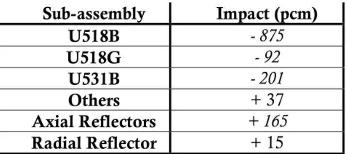
Table 4 : Impact of each assembly on global bias for SLB1 core in the rod inserted
configuration. Sub-assembly Impact (pcm) U518B - 875 U518G - 92 U531B - 201 Others + 37 Axial Reflectors + 165 Radial Reflector + 15
Table 4 shows that control rod sub-assemblies are responsible for the high discrepancy
in reactivity between APOLLO3® and TRIPOLI-4® in the rod inserted configuration. We also notice that the axial reflectors bias is significant, because of the two-step
1 We should consider an anisotropy correction because the treatment of transfer cross sections for order
higher than 0 is different between APOLLO3® and TRIPOLI-4®. The real flux solver bias is obtained at
calculation process (radial then axial calculation). The use of MOC-3D [12] shall reduce this bias, permitting us to perform a direct calculation of both axial reflectors.
IV.C. Validation of the new control rod sub-assembly representation at
Lattice level
In order to validate the new representation, we need to assess its accuracy by comparing its results to reference Monte-Carlo ones. To do so, we compare the infinite
multiplication coefficient resulting from an APOLLO3® sub-assembly calculation for
both representations defined consistently in Monte-Carlo calculation. The reference Monte-Carlo calculation is performed with TRIPOLI-4.9®, following 1 billion neutron histories leading to a precision better than 4 pcm (1 sigma) on 𝒌∞. The results are given in Table 5 and Table 6 for the three control rod sub-assemblies, with the old and the new representation.
Table 5 : Reactivity discrepancies for control rod sub-assembly calculations with isolated
representation
U518B U518G U531B TRIPOLI-4® 0.67479 0.87438 0.83785
APOLLO3® 0.67088 0.87135 0.83344
∆𝝆 (pcm) - 864 - 398 - 632
Table 6 : Reactivity discrepancies for control rod sub-assembly calculations with the cluster-type representation
U518B U518G U531B TRIPOLI-4® 1.05498 1.06990 1.21936
APOLLO3® 1.05235 1.06852 1.21692
∆𝝆 (pcm) - 236 - 121 - 165
The isolated representation gives poor results regarding reactivity discrepancies, especially with black control rods. With the new cluster-type representation, reactivity biases are more acceptable.
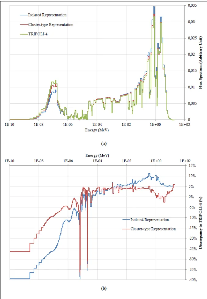
To measure the benefits of this new modeling regarding core calculations, we compare neutron flux spectrum in the control rods. The reference flux spectrum results from a TRIPOLI-4® core calculation, and is compared to the averaged flux spectrum measured in a U518B sub-assembly (cf. Fig. 7).
The new Cluster-type modeling is more representative of the core situation, especially in the thermal bump (discrepancy to TRIPOLI-4® goes from -25 % to -10 % at 0.1 eV). Moreover, the global behavior in the fast zone of the spectrum is improved. However, there are still some remaining biases in the resonance domain, especially for 238U resonance, at 6.63 eV and 20.8 eV. It is the topic of current studies to remove these remaining biases by using a refiner energy scheme with 361 groups associated to the sub-group method.
Fig. 7 : 281 groups control rod sub-assemblies’ flux spectrum comparison (a) and
IV.D. Impact of control rod sub-assembly representation on Core
calculations
The final goal of this new representation is to improve APOLLO3® core calculation accuracy against TRIPOLI-4® reference calculations, when control rods are fully inserted. Indeed, the control rod representation has no effect in the nominal configuration where control rods are fully removed (bias of + 95 pcm with the reference calculation scheme).
In Table 7, we will present the biases against TRIPOLI-4® for different APOLLO3® core calculations of the SLB reactor, with control rods fully inserted:
- Calculation 1: we use the Isolated representation for lattice calculation , with a
complete homogenization of control rod sub-assemblies for core calculation ;
- Calculation 2: we use the Cluster-type representation for lattice calculation, with a complete homogenization of control rod sub-assemblies for core calculation ;
- Calculation 3: we use the Isolated representation for lattice calculation, and the
semi-heterogeneous (3x3 zones) modeling of control rod sub-assemblies for core
calculation ;
- Calculation 4: we use the Cluster-type representation for lattice calculation, and the semi-heterogeneous (3x3 zones) modeling of control rod sub-assemblies for calculation.
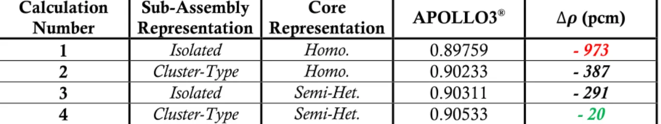
Table 7 : Impact of control rod sub-assemblies representation in APOLLO3® for SLB
core calculation (TRIPOLI-4® reference: k
eff = 0.90549) Calculation Number Sub-Assembly Representation Core Representation APOLLO3 ® ∆𝝆 (pcm) 1 Isolated Homo. 0.89759 - 973 2 Cluster-Type Homo. 0.90233 - 387 3 Isolated Semi-Het. 0.90311 - 291 4 Cluster-Type Semi-Het. 0.90533 - 20
Applying the standard APOLLO3®-LWR reference calculation scheme (Calculation
1) to the SLB1 core with control rods fully inserted doesn’t give satisfactory results. This
bias comes in fact from the approximate treatment of control rods sub-assemblies (isolated, the calculated spectrum is far from reality).
As we saw in the sub-assembly calculation, using the cluster-type modeling enabled us to improve control rod sub-assemblies calculation. This improvement is propagated through the core calculation, as we observe a 600 pcm gain between Calculations 1 and 2.
Thanks to the semi-heterogeneous (3x3 zones) modeling, the accounting of the shadowing effects leads to a 700 pcm reactivity gain between Calculations 1 and 3. In
Fig. 8, we plot the macroscopic fission rate’s radial profile (X-axis) in a control rod
sub-assembly for core calculations 2 and 4, and for the cluster-type lattice calculation. We compare those profiles with TRIPOLI-4® macroscopic fission rate’s radial profile in a control rod sub-assembly placed in the center of the core.
Fig. 8 : X-axis Fission Rates Profiles (a) and Comparison between X-axis and Diagonal
Profiles (b). Control rod positions (CR) aren’t represented for diagonal profiles, but you can refer to Fig. 5 to find them.
Plot (a) shows that the macroscopic fission rate profile shape for the Lattice calculation is consistent with the TRIPOLI-4® one. The values are different since the incoming flux is different for the two calculations. Concerning the core calculations, we see that the macroscopic fission rate profile for Calculation 2 doesn’t fit with the TRIPOLI-4® profile, since the depression behind peripheral control rods (CR1) is not observed. The semi-heterogeneous modeling fixes this issue. However, the increasing of the fission rate in the central zone is not described, since this part is homogenized (a representation cell by cell should be useful to avoid this problem but lead to more demanding computer resources for the core calculations).
Plot (b) stresses the interest of dividing the sub-assembly into 9 zones, rather than in 2 zones (a central one and a peripheral one). The fission rate is higher in the corners than in the sides, since there is less absorption in the corners1. Moreover, the corners are surrounded by three fissile sub-assemblies, whereas the sides are only next to one fissile
sub-assembly. Finally, the fission rate profile in the central zone is the same for every direction.
The combination of the two representations (Calculation 4) offers the best accuracy on keff, with a very low bias against TRIPOLI-4® (- 20 pcm). However, since this low discrepancy could be resulting from error compensations, we apply the bias decomposition on Calculation 4 (cf. Table 8).
Table 8 : Evolution of the bias decomposition from Calculations 1 to 4. Calculation 1 Calculation 4 Global bias (pcm) - 973 - 20 MINARET (pcm) - 75 - 67 Lattice Approximations (pcm) - 898 + 46
The refine computational scheme has an insignificant impact on the MINARET bias, its job was to improve the lattice approximations bias. We managed to divide by 20 this bias, hence improving the global accuracy of the calculation scheme.
CONCLUSION
In this paper, we present recent advances on PWR core calculations with the new deterministic multi-purpose neutronic transport code APOLLO3®. The standard reference calculation scheme for PWRs gives satisfactory results in the nominal configuration where all absorber rods are withdrawn, but poor results in rod inserted configurations. The main aim of this paper was to propose a new representation for control rod sub-assemblies, in order to improve those results.
The first part of this work was to improve the quality of the self-shielded cross sections generated at the Lattice calculation level. The new model consists in surrounding the control rod assemblies with fissile assemblies. This cluster-type representation permits us to be more representative of the core situation, since the neutron flux spectrum in the sub-assembly is closer to the one encountered in the core. Concerning reactivity effect, we have a 600 pcm gain in reactivity bias against TRIPOLI- 4 compared to the standard reference calculation scheme but a remaining bias of -387 pcm.
The other part of this work was to improve the representation of control rod sub-assemblies at the core level. Usually, sub-sub-assemblies are fully homogenized radially, but this modeling doesn’t take into account the absorber rod shadowing effects. In order to better represent these phenomena, we propose a partial homogenization of control rod sub-assemblies, which consists in dividing them into (3x3) zones. This modeling allows us to represent the depth of the fission rate profile after the peripheral control rods, and to highlight the difference of fission rate between corners and sides zones. At the end, we have a 700 pcm reactivity gain against TRIPOLI-4® thanks to this representation.
Finally, the refine computational scheme leads to a small -20 pcm reactivity bias against TRIPOLI-4® in rod inserted configuration, without using any equivalency method. This work lays the foundations for an advanced APOLLO3®-LWR reference calculation scheme, on-going works being devoted to the replacement of the Fine Structure self-shielding method by the subgroup method (361 energy groups, or the use of more accurate reflector models).
A
CKNOWLEDGMENTSAPOLLO3 and TRIPOLI-4 are registered trademark of CEA. We gratefully acknowledge CEA, AREVA and EDF for their long term partnership and their support. The first author would like to thank the APOLLO3 development team for their efforts in implementing the models described here.
R
EFERENCES[1] D. Schneider, F. Dolci, F. Gabriel, J. Palau, M. Guillo and B. Pothet, "APOLLO3®: CEA/DEN Deterministic Multi-purpose code for Reactor Physics Analysis," in PHYSOR 2016, Sun Valley,USA, May 1-5, 2016.
[2] R. Sanchez, J. Mondot, Z. Stankovski, A. Cossic and I. Zmijarevic, "APOLLO2: a user oriented, portable, modular code for multigroup transport assembly calculations," Nuclear Science and Engineering, pp. 352-362, 1988.
[3] J. Lautard, C. Magnaud, F. Moreau and A. Baudron, "CRONOS2: un logiciel de simulation neutronique des coeurs de réacteur," Technical Report, Saclay, France, 2000.
[4] G. Rimpault and al., "The ERANOS code and data system for fast reactor neutronic analyses," in PHYSOR 2002, Seoul, South Korea, October 7-10, 2002. [5] D. Diamond, "Experience using phenomena identification and ranking table
(PIRT) for nuclear analysis," Proceedings of PHYSOR 2006, vol. 4, pp. 1931-1938, 2006.
[6] C. Diop and al., "TRIPOLI-4®: a 3D continuous energy Monte Carlo Transport code," in PHYTRA-1, Marrakech, Morocco, March 14-16, 2007. [7] A. Santamarina and al., "APOLLO2.8 : A Validated Code Package for PWR
Neutronics Calculations," in Advances in Nuclear Fuel Management IV (ANFM
2009), Hilton Head Island, South Carolina, USA, April 12-15, 2009.
[8] M. Livolant and F. Jeanpierre, "Autoprotection des résonances dans les réacteurs nucléaires - application aux isotopes lourds," 1974.
[9] R. Sanchez and A. Chetaine, "Synthetic acceleration for a 2D characteristic method in non regular meshes," in M&C 1999, Madrid, Spain, September 1999. [10] A. Calloo, "Développement d'une nouvelle modélisation de la loi de choc
dans les codes de transport déterministe," PhD Thesis, 2012.
[11] J.-Y. Moller, J.-J. Lautard and D. Schneider, "MINARET, a deterministic neutron transport solver for nuclear core calculations," in M&C 2011, Rio de Janeiro, Brazil, May 8-12, 2011.
[12] P. Archier, J.-M. Palau and J.-F. Vidal, "Validation of the newly implemented 3D TDT-MOC Solver of APOLLO3® code on a whole 3D SFR Heterogeneous Assembly," in PHYSOR 2016, Sun Valley, Idaho, USA, May 1-5, 2016.

![[PDF] Cours programmation web html pdf les bases | Cours Informatique](data:image/gif;base64,R0lGODlhAQABAIAAAP///wAAACH5BAEAAAAALAAAAAABAAEAAAICRAEAOw==)