HAL Id: cea-02380887
https://hal-cea.archives-ouvertes.fr/cea-02380887
Submitted on 26 Nov 2019
HAL is a multi-disciplinary open access
archive for the deposit and dissemination of
sci-entific research documents, whether they are
pub-lished or not. The documents may come from
teaching and research institutions in France or
abroad, or from public or private research centers.
L’archive ouverte pluridisciplinaire HAL, est
destinée au dépôt et à la diffusion de documents
scientifiques de niveau recherche, publiés ou non,
émanant des établissements d’enseignement et de
recherche français ou étrangers, des laboratoires
publics ou privés.
Conceptual design of ASTRID fuel sub-assemblies
Thierry Beck, Victor Blanc, Jean-Michel Escleine, David Haubensack, Michel
Pelletier, Mayeul Phelip, Benoît Perrin, Christophe Venard
To cite this version:
Thierry Beck, Victor Blanc, Jean-Michel Escleine, David Haubensack, Michel Pelletier, et al..
Con-ceptual design of ASTRID fuel sub-assemblies. Nuclear Engineering and Design, Elsevier, 2017, 315,
pp.51-60. �10.1016/j.nucengdes.2017.02.027�. �cea-02380887�
Conceptual design of ASTRID fuel sub-assemblies
Thierry BECKa, Victor BLANCa, Jean-Michel ESCLEINEa, David HAUBENSACKb, Michel PELLETIERa, Mayeul PHELIPa, Benoît PERRINc, Christophe VENARDb
a
CEA Cadarache, DEN, DEC, F-13108 Saint-Paul-lez-Durance, France b
CEA Cadarache, DEN, DER, F-13108 Saint-Paul-lez-Durance, France cAREVA-NP, 10 rue J. Récamier, 69456 Lyon Cedex 06, France
Corresponding author: Thierry BECK, [email protected]
ABSTRACT
The French 600 MWe Advanced Sodium Technological Reactor for Industrial Demonstration (ASTRID) project has reached the end of its Conceptual Design phase. The core design studies are being conducted by the CEA with support from AREVA and EDF. Innovative design choices for the core have been made to comply with the GEN IV reactor objectives, marking a break with the former Phénix and SuperPhénix Sodium Fast Reactors. The main objective to improve safety compared with current GEN II or III reactors led to a core design that demonstrates intrinsically safe behaviour. A negative sodium void worth is achieved thanks to a new fuel sub-assembly design including (U,Pu)O2 and UO2 axially heterogeneous fuel pins, a large cladding/small spacer wire bundle, a sodium plenum above the fuel pins, and upper neutron shielding with both enriched and natural boron carbide (B4C) which also maintain a low secondary sodium activity level. As these Na-bonded B4C pins can lead to the retention of unacceptable amounts of sodium, the whole upper neutron shielding has been made removable on-line through the sub-assembly head just before the washing operations. Finite elements calculations have been performed to increase the stiffness of the stamped spacer pads in order to analyse its effect on the core mechanical behaviour during hypothetical radial core flowering and compaction events. More generally, all design choices for ASTRID have been made with the permanent objective of minimising the sub-assembly height to decrease the overall costs of the boiler reactor and the fuel cycle.
This paper describes the fuel sub-assembly design for the ASTRID CFV v4 core at the end of the Conceptual Design phase (AVP2). Focus is placed on innovations and specificities in the design compared with former French SFRs.
Keywords
ASTRID, SFR, fuel, sub-assembly.
1. Introduction
The French 600 MWe sodium-cooled fast reactor demonstrator called ASTRID has just reached the end of its Conceptual Design phase (AVP2). The aim of the past three years (2013-2015) of studies was to propose a consistent, innovative preliminary design (Rouault et al., 2015). The core design studies are being conducted by the CEA with support from AREVA and EDF. Innovative design choices for the core have been made to comply with the GEN IV reactor objectives, thereby marking a break with the former Phénix and SuperPhénix French Sodium Fast Reactors.
The main objective to improve safety levels compared with current GEN II or III reactors has led to a core design that shows intrinsically safe behaviour in transients of accident situations. A negative or null sodium void worth can be obtained by using a heterogeneous core (CFV). Other challenging objectives such as minimising the secondary sodium activity level, preventing reactivity insertions due to core compaction and applying cost-killing measures have led to a rather new fuel sub-assembly design compared with former SFRs.
This paper describes the design of the fuel sub-assembly (S/A) for the ASTRID CFV v4 core (version 4) at the end of the Conceptual Design phase with focus on innovations and specificities.
2. CFV Core
The layout of the CFV v4 core remains the same as the v3 core previously described in Venard et al., 2015. The major changes integrated into v4 concern some specific details of the sub-assembly design, with no
significant impact on the core performance levels.
The CFV v4 core architecture consists of 180 inner fuel sub-assemblies and 108 outer fuel sub-assemblies, surrounded by 3 rows of reflector sub-assemblies with MgO, 3 rows of shielding sub-assemblies with B4C, 3 rows of shielding sub-assemblies with MgO, and another 2 rows of shielding sub-assemblies with B4C. The lateral reflector and shielding arrangement was optimised to provide enhanced radial neutron absorption (Chapoutier et al., 2015). The core’s absorber device relies on an innovative architecture composed of 9 control/shutdown rods and 9 diverse control/shutdown rods (Guénot-Delahaie et al., 2013), which are used both to manage core reactivity during the cycle, and to shut down the reactor. The other main characteristics of the ASTRID core include the integration of Complementary Safety Devices (CSD) for severe accident prevention (Guénot-Delahaie et al., 2016) and mitigation, and an internal storage and debugging positions in the lateral shielding area.
The safety and performance goals (Varaine et al., 2012) assigned to the CFV core can be summarised by:
• Intrinsically safe behaviour, possibly supplemented by CSD during Unprotected Loss-Of-Flow (ULOF) transients and unprotected Control Rod Withdrawal (CRW) events.
• Negative sodium void worth (CFV core).
• Search for the best performance in terms of fuel burn-up and S/A residence times.
The core is managed on the basis of 4 batches of fuel sub-assemblies. The objective fuel residence time is 1440 EFPD and the equilibrium cycle length is 360 EFPD. The fuel S/A positions are divided into 5 different flow zones to get a flat temperature distribution. The sodium flow rate required through each zone, varying between 22.5 and 26.7 kg/s, is calculated according to the fission heat generation and design criteria of a nominal cladding temperature lower than 620°C (best estimate) and an outlet temperature dispersion between two neighbouring sub-assemblies lower than 50°C. The whole core pressure drop is close to 3 bars.
3. Overview of the fuel sub-assembly
Although the overall design of the ASTRID fuel S/A mainly relies on feedback from French SFRs Phénix and SuperPhénix, the CFV core concept involves some appreciable differences (Varaine et al., 2012):
• Axially heterogeneous fuel pins with a thick internal fertile plate for the inner core.
• Longer fissile zone for the outer core.
• Large cladding/small spacer wire fuel bundle.
• Sodium plenum (30 to 40 cm) above the fissile area.
• Enriched B4C zone at the bottom of upper neutron shielding. Due to washing considerations, this component is made removable through the S/A head.
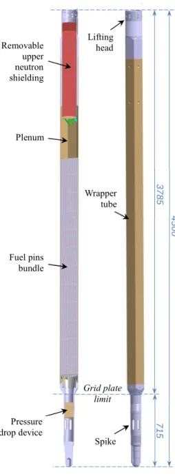
A schematic diagram of the CFV v4 fuel S/A is given in Fig. 1. The main parts are detailed in the following paragraphs.
Fig. 1. ASTRID CFV v4 fuel subassembly.
Cost-killing processes performed at the end of the project’s pre-conceptual design phase (AVP1) (Chenaud et al., 2013) confirmed the objective of minimising the S/A height to decrease the overall costs of the reactor and the fuel cycle. A core height reduction of about 0.5 m was possible for ASTRID thanks to removal of the upper axial blanket used in former SFRs, coupled with the choice of a compact pressure drop device making it possible to shorten the spike by another 0.4 m. This resulted in a total S/A height of 4.50 m which has been reduced by 0.9 m compared with SuperPhénix (5.40 m), and which is not much higher than Phénix S/A (4.30 m). 4. Detailed description
4.1. Fuel Pins
One major innovation that has helped reducing the core’s sodium void effect by about 5$ (Varaine et al., 2012; Chenaud et al., 2013) compared with previous reactors is the wide fuel pin/small wire concept. The ASTRID design consists of 217 fuel pins in each S/A with a 9.70 mm outer diameter separated by a 1 mm-diameter spacer wire helically wound around the pins. The pin’s lower plugs are mounted on the rails of a stainless-steel single-part grid to form a bundle (Fig. 2) that is vertically held within the hexagonal wrapper tube.
Removable upper neutron shielding Grid plate limit 4 5 0 0 3 7 8 5 7 1 5 Plenum Lifting head Fuel pins bundle Wrapper tube Spike Pressure drop device
Fig. 2. Fuel pin bundle with the grid support.
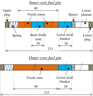
The inner and outer core fuels pins differ slightly by their composition and their length (Fig. 3). The CFV core is characterised by axially heterogeneous fuel pins, with a UO2 fertile zone inside the (U,Pu)O2 fissile area for the inner fuel sub-assemblies. A 10 cm-longer fissile zone for the outer fuel sub-assemblies provides a global asymmetrical, crucible-shaped core. Fuel pins in the core are provided with a lower fertile axial blanket of 30 cm. Fissile pellets have a central hole to improve margins with respect to the fuel melting temperature, while fertile pellets are solid to increase the breeding gain, to reduce the loss of reactivity and to make it possible to be differentiated from fissile pellets.
Fig. 3. Fuel pins composition (dimensions in cm).
Fuel pins are hermetically sealed once filled with a helium-based mixture at 1 bar. Thermomechanical analysis based on finite-element computations of the fuel pins during irradiation have started with the CEA code called GERMINAL V2 (Lainet et al., 2013) within the PLEIADES fuel simulation platform (Helfer et al. 2015). The aim of this analysis is to check that the design criteria (maximal temperatures, mechanical constraints,
217 fuel pins bundle Grid 20 Upper plug
Inner core fuel pin
Outer core fuel pin Lower axial blanket Spring Fissile zones Lower plenum Lower plug Spacer Inner fertile zone 80 Lower axial blanket Fissile zone 90 213 223 30 30
cladding swelling, etc.) are met in nominal conditions and incident transients (CRW, etc.), and to estimate a number of pin failures to be expected during severe accident sequences using a statistical analysis technique. By avoiding excessive pressurisation in the pins, the lower plenum length will undoubtedly be the key point of these in-depth studies. In nominal conditions, the end-of-life pressure in the pins reaches about 40 bars.
Life duration of the fuel element is limited by the cladding embrittlement due to the high radiation damage rate. The reference cladding material for ASTRID is composed of special 15%Cr-15%Ni austenitic steel (Le Flem et al., 2014) which was tested in Phénix: AIM1 (Austenitic Improved Material #1). The level of cold-work (~20%), stabilisation by titanium, and control over the amounts of minor elements (Si and P) have made it possible to delay the beginning of swelling under irradiation, which makes AIM1 suitable for use up to high dose rates. AIM1 has also been chosen for the spacer wire to prevent differential behaviour under irradiation. A dedicated qualification programme is required on the upper plug/cladding welding which is subjected to a higher dose rate in the CFV core.
4.2. Wrapper Tube and Spacer Pads
The closed leaktight hexagonal wrapper tube (hexcan) is made of EM10 steel which has been extensively tested in Phénix. This martensitic 9%Cr-1%Mo steel exhibits excellent dimensional stability under irradiation (Le Flem et al., 2014). A record dose of 155 dpa was reached on the EM10 hexcan during the BOITIX-9 experiment in Phénix, with a resulting irradiation swelling limited to 0.5%. At the beginning of the ASTRID project, the slight geometrical variation expected for the EM10 wrapper tubes at the target dose has made it possible to optimise the core by reducing the duct wall thickness and the inter-assembly gap compared with austenitic 316Ti SuperPhénix hexcans. The external and internal widths of the ASTRID hexcan are respectively 168.7 mm and 161.5 mm.
To ensure suitable clearance between the sub-assemblies in the core, a rectangular spacer pad is stamped through each side of the hexcan just above the fuel pins (Fig. 4). This pad design was originally used in Phénix and SuperPhénix, and renewed for ASTRID because of its reliability and its simplicity.
Fig. 4. Section of a hexagonal wrapper tube with stamped spacer pads.
Not only do the pads play a central role in the mechanical equilibrium of the core, they also enhance safety by preventing reactivity increases due to a core compaction that follows a flowering, which may occur when core is subjected to dynamic stresses such as earthquake or internal pulse load release. Following the safety requirements for ASTRID wherein core compaction must be minimised, studies have been engaged to analyse the effect of a pad stiffness increase on the core mechanical behaviour. For this purpose, extensive studies have been performed to increase the stiffness of the stamped pads (Blanc et al., 2015).
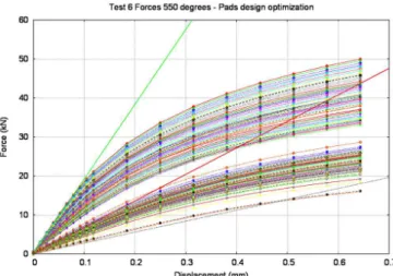
Finite element calculations have been done using the LICOS code (Helfer et al. 2015b) based on the CAST3M solver within the PLEIADES fuel simulation platform (Helfer et al. 2015a). A model was first developed to reproduce the cold stamping process and obtain representative pad geometry, and then was validated on the SuperPhénix pads geometry thanks to comparison with available experimental results of duct crushing tests at 550°C. A parametric study considering variations in the pad dimensions (height, width, radius in the corners) was performed for the 6-loaded-pad configuration using an elastoplastic law of EM10 at 550°C. More than 200 plots were generated to cover the range of parameters (Fig. 5).
Thickness Wrapper tube
Fig. 5. Pad design optimisation - Crushing computations.
Stiffness is defined by the slope of the curves in the elastic zone (small displacements). The highest stiffness of 192 kN/mm was obtained for the extremal parameters: maximal width, maximal height and minimal radius of the pads. These computations showed that pad stiffness could be increased by a maximal ratio of ~7 compared with the previous reference design.
The final pad design for ASTRID will be defined following the core static and dynamic mechanical behaviour studies that are currently in progress.
4.3. Upper Neutron Shielding
Up to now, the upper neutron shielding is by far the component that has required the most brainstorming and iterative studies. The result is an innovative design covered by a patent application (Lorenzo et al., 2014).
4.3.1. ASTRID Requirements
The CFV core’s requirement for ASTRID makes it impossible to reuse the upper neutron shielding designs of Phénix and SuperPhénix. Indeed, the new requirement specifies a negative sodium void worth. For this reason, the bottom of upper neutron shielding, located just above the sodium plenum, should reflect neutrons as little as possible. This required choosing the best neutron absorber – boron carbide (B4C) – which benefits from extensive feedback since it has been used in SFR absorber rods. Core studies (Venard et al., 2015) concluded that the optimum design for reaching the CFV effect would be a lower part made of 7.5 cm-thick B4C enriched to 90% in 10B for enhanced absorption, together with the smallest steel structure thickness to minimise neutrons reflection.
The second main function assigned to the upper neutron shielding is obviously to provide proper axial neutron shielding to minimise damage to reactor internals and reduce the activation of surrounding Na circuits. The specification for ASTRID is a target 24Na activity level less than 10 Bq/cm3 (best-estimate calculation) for the secondary sodium in the intermediate heat exchangers (IHX) to ensure that the ASTRID steam generator building remains classified as a non-controlled area. This objective is much more severe than for Phénix, and also more difficult to meet than for SuperPhénix because of the distance between the IHXs and the core which is reduced. Moreover, considering the inherent tendency of the CFV core to amplify upper neutron leakages (due to the suppression of the upper fertile axial blanket), and the limited available space (about 90 cm) in the top the S/A (to meet a total height of 4.50 m), it is clear that the upper neutron shielding is a key issue.
Extensive 3D Monte-Carlo calculations were conducted to optimise the ASTRID core shielding, considering the best “performance vs. cost” ratio (Chapoutier et al., 2015). This consisted in identifying the best arrangement for the reflector, moderator and absorber materials in the lateral shielding sub-assemblies, as well as the material in the top part of the upper neutron shielding. Concerning the lateral shielding, successive alternations of MgO and B4C sub-assemblies were adopted (see Section 0). Concerning the upper neutron shielding, the top part was filled with natural B4C (19.78% of 10B), the best neutron absorber, which gave almost as good results as 10 B-enriched B4C, while being much less expensive. Additional neutron shields made of borated steel sleeves were added in parallel to the IHXs to decrease the secondary sodium activation to an acceptable level of about 8 Bq/cm3.
4.3.2. Upper Neutron Shielding Design
Knowing that the upper shield needed to be made of both enriched and natural B4C (see previous section), the other complex part of the task consisted in proposing a design compatible with the design criteria and operational constraints.
The axially heterogeneous fuel pins provide a maximal flux shifted towards the top of the sub-assemblies compared with former SFRs. This means that the B4C-enriched lower part of the neutron shielding is subjected to a higher flux (3.0E+14 n/cm2/s) which produces a large volume of helium (~330 dm3) and dissipates a great deal of power (up to 50 W/cm3) due to the exothermal 10B(n,α)7Li neutron capture reactions. The latter aspect led to the choice of B4C in the form of a 19-pin bundle to meet the maximal temperature criterion, together with a Na-bond to take advantage of the high thermal conductivity of sodium. Non-leaktight pins design also provided a solution to the problem of significant helium production. By allowing He to be released from the pins, any unacceptable pressurisation is avoided inside the pins and the height of the pins – i.e. the fuel S/A – is by the way minimised, because axial plenum is no longer necessary.
But Na-bonded pins maybe raised the most important issue that needed to be resolved. Absorber pins comprise a lower and an upper porous vent through which helium is released and sodium flows inside the pins. Due to the fragmentation of B4C under irradiation, small fragments may plug the micrometric pores of the vents and hinder pin draining. This is made even more difficult when considering the sub-millimetre cladding-pellet gap inside the pins. It is well-known that the sodium inside the Na-bonded absorber pins cannot be totally removed after draining. Yet this non-negligible amount of Na trapped inside the pins engenders unacceptable safety risks during the fuel S/A washing or underwater storage phases due to possible uncontrolled exothermal sodium-water reactions The solution to this problem was found following a brainstorming and value engineering process: the whole upper neutron shielding would be made removable on-line through the assembly head just before the washing operations.
The main difficulty was to design a device which enables the upper shielding extraction and that fulfilled the following requirements:
• The whole upper shielding must be removable on-line from the S/A head while in the washing pit.
• The smallest possible axial dimension must be applied to maximise the B4C pin height within the overall available space.
• The upper neutron shielding must be securely locked in position in the S/A, by acting against the hydraulic lift force.
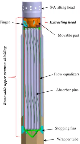
The extracting device is located at the top of the upper neutron shielding. It was designed on the basis of the experimental capsules head from SuperPhénix which were removable from the S/A in the outer Na storage area. A strict design process was carried out to reduce its length by a factor of ~4. The upward axial locking of neutron shielding is ensured by three lateral fingers spread out inside a groove in the S/A head and maintained thanks to the weight of a movable solid stainless steel part (Fig. 6). The downward axial locking is ensured by stopping fins located in the hexcan corners and mounted on a cylindrical skirt fixed to the S/A head structure. The three locking fingers are withdrawn by the upward movement of the movable part, allowing the upper neutron shielding to be extracted by the top through the S/A head. The translation motion of the movable part is ensured by a specific mechanical grapnel actuated in the washing pit and whose fingers are inserted in an internal groove. This grapnel is very similar to the one used for S/A lifting but with smaller dimensions.
The removable upper neutron shielding consists of a 14.5 cm-diameter and 94 cm-long cylinder. These dimensions comply with a S/A height of 4.50 m while fulfilling all ASTRID requirements.
Fig. 6. Removable upper neutron shielding inside the S/A (section view).
The lower part of the neutron shield, in its first design, comprises the 19-pin bundle equipped with flow equalisers, while the upper part comprises the extracting head as described above. The pins are attached to the fixed part of the extracting head thanks to a grid support composed of parallel rails, like the fuel pins (see Section 4.1). The pin design is equivalent to the one used for the absorber rods. It comprises a cladding made of 15-15Ti AIM1 stainless steel, capped by two plugs equipped with a porous vent. From bottom to top inside the pins, there are 7.5 cm of B4C enriched to 90% in 10B, 69.5 cm of natural B4C, and an upper plenum comprising a spring. The pins have a diameter of 25.8 mm and are separated by a 2 mm-diameter helical spacer wire. The surface fraction of B4C is 26.5%. B4C pellets are confined by a stainless steel shroud and are fabricated according to a “carbothermal” process instead of the “magnesiothermal” process (Phénix feedback). Like the control and shutdown rods (Guénot-Delahaie et al., 2013), the shroud and the “carbothermal” B4C are both the subject of in-depth R&D actions that aim to double the pin lifetime from start-up value which is based on feedback (two cycles of 360 EFPD) to the required full lifetime at equilibrium (four cycles of 360 EFPD).
4.3.3. Thermal-Hydraulic CFD Computations
CFD computations were performed first on a preliminary design, then on an optimised design.
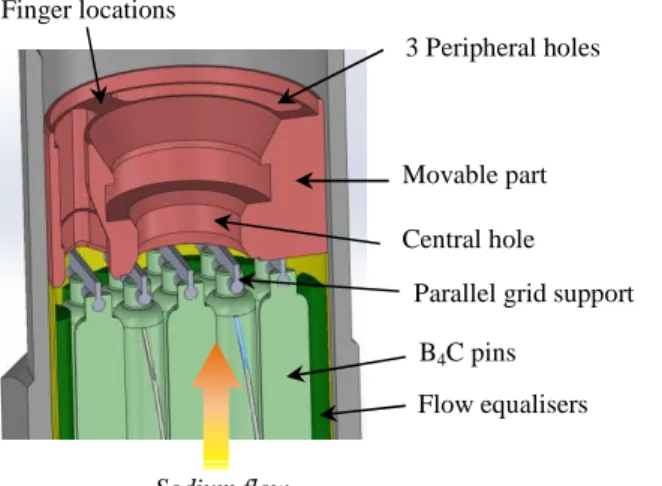
The movable part in the extracting head does not only ensure the locking/unlocking and extraction of the upper neutron shielding, but also the sodium flow path to the S/A outlet. A small central hole in the preliminary design was necessary to house the actuating mechanism of the three fingers. This sodium section reduction was expected to increase the pressure drop in the S/A. Three peripheral bean-shaped holes were consequently added between the fingers to increase the hydraulic diameter and reduce the total pressure drop (Fig. 7).
Wrapper tube R em o va b le u p p er n eu tr o n s h ie ld in g Movable part Finger
S/A lifting head
Absorber pins
Stopping fins
Extracting head
Fig. 7. Simplified cross-section of the upper shielding extracting head (fingers not represented). First design. Preliminary thermal-hydraulic calculations on this first design were performed to evaluate the pressure drop and to characterise the sodium flow fields (velocity and temperature) above the S/A outlet at the core monitoring system level (thermocouples and flowmeter). It is required to have the more homogeneous flow at the
monitoring level to ensure a proper protection of the core, with measured values as close as possible to the mean values at the S/A output. Simplified but representative modelling of the S/A upper zone was used with the CFD STAR-CCM+ code, starting from fuel pins output up to the monitoring system in the hot pool. A constant sodium flow rate was considered at the inlet of the modelled area, corresponding to the maximum value in the core (26.7 kg/s), but with the heterogeneous temperature map that was separately computed at the fuel bundle output. The mean temperature is 555°C at the S/A outlet.
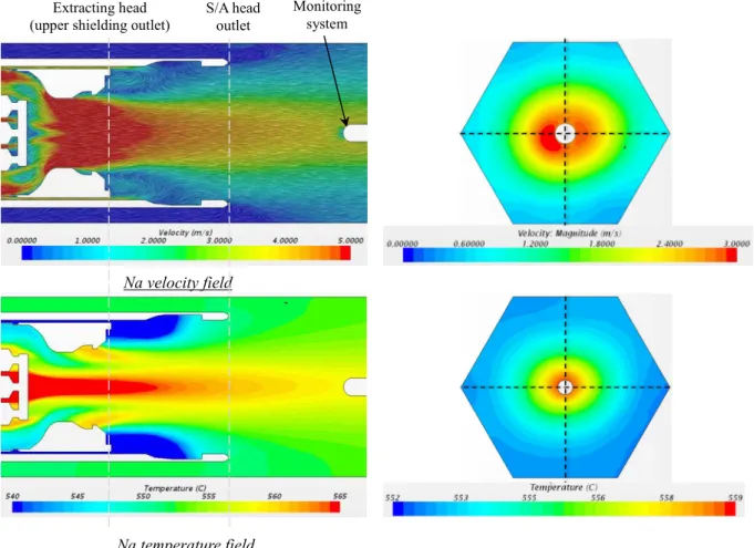
The sodium velocity and temperature fields at the sub-assembly outlet are shown in Fig. 8. This figure shows a heterogeneous flow in temperature with a gradient of ~13°C between the center and the periphery in the monitoring section plane, with a measured value 9°C higher than the mean temperature. The velocity field shows that the flow is much more disturbed as it goes through the extracting head of the upper shielding. The central and the three peripheral holes in the movable part create four separated flows at the S/A outlet. The peripheral flows have a velocity higher than the central one, which may alter the measure by the flowmeter. The total pressure drop in the upper shielding is ~0.6 bar, 90% of which is located in the absorber pins bundle because of the wires and flow equalisers that reduce the sodium section.
Movable part Sodium flow Flow equalisers part 3 Peripheral holes Central hole Finger locations B4C pins
Fig. 8. Primary CFD computations at the S/A outlet (first design). Left: along Z-axis; Right: in monitoring section plane.
These preliminary computations revealed several ways of optimising the pins bundle and extracting head design in order to improve the temperature and velocity fields at the sub-assembly outlet and to decrease the total pressure drop.
First, the wires and flow equalizer were removed, in order to enlarge the sodium section in the pins bundle. The parallel grid support was replaced by a symmetrical star-shaped one, to avoid heterogeneous flow
separation, and a similar star-shaped holder was included at the bottom of the pins bundle, to ensure its stability now that wires do not endorse this role anymore. At last, the movable part in the extracting head was simplified: the three peripheral holes were suppressed while the central hole was enlarged with a smoother entrance to reduce the pressure drop (Fig. 9).
Fig. 9. Simplified cross-section of the upper shielding extracting head (fingers not represented). Second design. The sodium velocity and temperature fields at the sub-assembly outlet are shown in Fig. 10.
Na velocity field
Na temperature field Extracting head
(upper shielding outlet)
S/A head outlet Monitoring system Movable part Sodium flow Central hole B4C pins Star-grid support
Fig. 10. Secondary CFD computations at the S/A outlet (second design). Left: along Z-axis; Right: in monitoring section plane.
This figure shows a more symmetrical and flat response in temperature with a gradient of ~5°C between the center and the periphery in the monitoring section plane, with a measured value just 4°C higher than the mean temperature at S/A outlet. The velocity field shows that the flow is much more homogeneous and acceptable too with a single flow at the monitoring system level. The velocity is higher in the center of the flow which is supposed to increase the accuracy of the measurement. The total pressure drop in the upper shielding is decreased to ~0.3 bar, which represents a reduction by ~0.3 bar comparatively to the previous design.
4.4. Lifting Head
The S/A lifting head was designed in coherence with the upper neutron shielding (see previous section). The objective of maximising the B4C volume in the removable upper shielding led to increasing the head inner diameter (15 cm) through which it is extracted. The sub-assembly head is a ~1 meter-long single part made of AISI 316L stainless steel. The top part is cylindrical while the bottom part is hexagonal (Fig. 11).
The cylindrical top part of the head is 27 cm-long. It comprises an internal groove at the top for
sub-assembly lifting using the handling grapnel. Several radial holes will be included to ensure proper S/A cooling in the case of exceptional situations where heads are uncovered for visual inspection. The top outer surface is used for surface detection purposes by the under-sodium visualisation system (VISUS), which is designed to ensure that the S/A head does not stick out further than the others. To prevent handling errors, a bar code is engraved on the edge of the head for sub-assembly identification by under-sodium ultrasonic readings.
Na velocity field
Na temperature field Extracting head
(upper shielding outlet)
S/A head outlet
Monitoring system
Fig. 11. Lifting head.
The bottom part of the head has an outer hexagonal section while retaining the inner cylindrical hole. It is extended downwards to the interface between the enriched B4C and the natural B4C of the upper neutron shielding (Fig. 6). This design was necessary to provide the negative sodium void effect by limiting the amount of steel (neutron reflector) in the bottom of the upper shielding. Moreover, the steel in the upper part of the head, which is next to the natural B4C, improves the global upper neutron shielding and helps to achieve a low secondary sodium activity level. The hexagonal part of the head is inserted inside the wrapper tube with a gap. The binding with the wrapper tube is ensured by cold stamping after mounting of the fuel pins bundle.
4.5. Spike
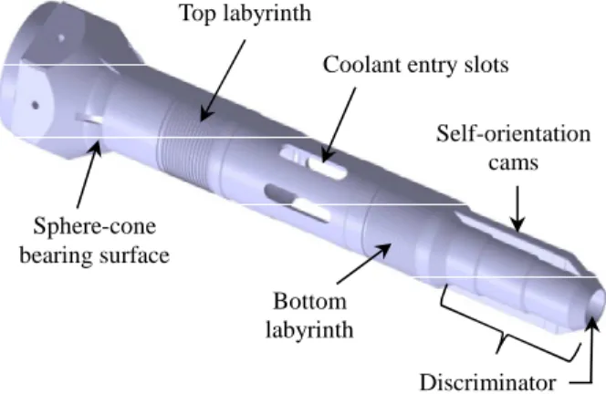
All core sub-assemblies are supported vertically with the spike inserted in the shroud tubes provided in the grid plate. The bearing surface is spherical on the spike side and conical on the grid plate side (Fig. 12). The shroud tubes comprise multiple holes to allow cold sodium from the grid plate to flow into the S/A spike through oblong slots.
Two helicoid labyrinths are provided on the spike with a reduced gap with the shroud tube. The function of the top labyrinth is to control the leakage flow of cold sodium – ~200 kg/s for the whole core – into the hot pool in the interspace between sub-assemblies. The spherical bearing is provided with six slots to prevent cavitation and erosion at this level due to the leakage.
The function of the bottom labyrinth is to ensure the minimum flow required for main vessel cooling. It also prevents the S/A from hydraulic lifting or floating, which may occur due to high coolant drag pressure, by generating a hold-down force owing to the pressure drop developed here.
Fig. 12. Spike. Wrapper tube Bar code VISUS detection zone Stamping points S/A lifting head Inner lifting groove
Top labyrinth
Bottom labyrinth
Coolant entry slots
Discriminator Self-orientation
cams Sphere-cone
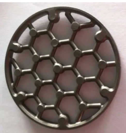
The choice of a compact pressure drop device for ASTRID made it possible to reduce the spike length by about 0.4 m compared with the SuperPhénix design equipped with diaphragm-plates device. Sub-assemblies of each flow zone in the core are equipped with a compact pressure drop in the spike to achieve the required flow rate through the S/A (Fig. 1). This compact device consists of multiple aligned or crossed honeycomb orifice plates (Fig. 13), within a total length of less than 15 cm. This device has been successfully experimented with some sub-assemblies in Phénix and SuperPhénix.
Fig. 13. Grid plate of the pressure drop device.
Additional protection against handling errors during refueling is provided thanks to discriminatory features located at the bottom of the spike. Those discriminators have a specific design for each flow zone in the core. They prevent a fuel S/A from being completely lowered into the wrong position in the core, i.e. in a position where the S/A would be under-cooled, or in a position of an absorber rod that would lead to a reactivity increase. This protection involves a combination of inner and outer diameters at the spike’s end that are reproduced on a lock located inside the shroud tubes (Fig. 14).
Though this discriminator concept comes from SuperPhénix, the novelty for ASTRID is that the spike end is provided with self-orientation devices. These devices are arranged in parallel to the discriminator at the bottom of the spike, instead of being located at the top just above the grid plate as was the case for former SFRs. The discriminator consists of two cams at the spike end coupled with six vertical grooves inside the shroud tubes. The top of each groove is provided with conical ramps to rectify the angular mis-orientation. While refueling, self-orientation guarantees the angular position of each S/A with a good accuracy with respect to the grid plate. Such an orientation with respect to the fixed structure of the grid plate prevents the S/A network from angular drift that may cause S/A blockages while refueling, and guarantees the proper S/A orientation even in case of refueling after a WCD, i.e. without adjacent sub-assemblies.
Fig. 14. Discriminatory and self-orientation features.
The spike is made of AISI 316L austenitic steel. Its thickness will be defined according to the results of the core dynamic mechanical studies that are currently underway.
All core sub-assemblies have the same spike design except for the discriminator which depends on the flow zone, and for the mitigation CSD which have a specific spike.
5. Conclusion
The fuel sub-assembly design for the ASTRID CFV v4 core at the end of the Conceptual Design phase (AVP2) is described.
Innovative design choices have been made to meet the ASTRID project requirements, marking a break with the former Phénix and SuperPhénix French SFRs. A negative sodium void worth (CFV core) will be achieved thanks to axially heterogeneous fuel pins, a wide cladding/small spacer wire bundle, a sodium plenum above the fuel pins, and upper neutron shielding with both enriched and natural B4C sodium-bonded pins.
The upper neutron shielding will help to reach a low secondary sodium activity level and will be removable on-line through the assembly head so as to meet washing constraints. Studies have been performed to increase the stiffness of the stamped spacer pads in order to analyse its effect on the core mechanical behaviour during hypothetical radial core flowering and compaction events. To prevent handling errors, an under-sodium ultrasonic bar code identification system will equip the lifting head, and the spike end will be fitted with discriminatory features arranged in parallel to self-orientation devices.
The beginning of the next Basic Design phase now focuses on consolidation of main design choices, performance levels confirmation, design optimization, as well as the start of qualification programme. Acknowledgments
The authors wish to thank all the teams involved in the fuel S/A design studies at CEA and AREVA-NP for their support.
References
Blanc, V. et al., 2015. Characterization, Simulation and Improvement of Spacer Pads Mechanical Behaviour for Sodium Fast Reactor Fuel Subassemblies. In: Transactions of SMIRT23, Paper 634, Manchester, UK, August 10-14, 2015.
Chapoutier, N. et al., 2015. ASTRID Core Shielding – Design Studies and Benchmark Analysis. In: Proceedings of ICAPP, Paper 15305, Nice, France, May 3-6, 2015.
Chenaud, M.S. et al., 2013. Status of the ASTRID Core at the End of the Pre-conceptual Design Phase 1. Nucl. Eng. Technol. 45 (6).
Self-orientation cams Lock
Ramps
Shroud tube side S/A spike
Guénot-Delahaie, I. et al., 2013. State of the Art of the Conceptual Designs for ASTRID Control and Shutdown Rods. In: Proceedings of FR13, Paris, France, March 4-7, 2013.
Guénot-Delahaie, I. et al., 2016. The Innovative RBH Complementary Safety Device for ASTRID to Address Unprotected Loss of Flow Transients: From Design to Qualification. In: Proceedings of ICAPP, Paper 16116, San Francisco, USA, April 17-20, 2016.
Helfer, T. et al., 2015. Recent Improvements of the Thermomechanical Modelling in the PLEIADES Platform: Applications to the Simulation of PWR Accidental Transient Conditions Using the Alcyone Fuel Performance Code. In: Workshop NuFuel & MMSNF, Karlsruhe, Germany, November 16-18, 2015.
Helfer, T. et al., 2015. LICOS, a Fuel Performance Code for Innovative Fuel Elements or Experimental Devices Design. Nucl. Eng. Des. 294, 117-136.
Lainet, M. et al., 2013. Recent Modelling Improvements in Fuel Performance Code GERMINAL for SFR Oxide Fuel Pins. In: Proceedings of FR13, Paris, France, March 4-7, 2013, CN-199/241.
Le Flem, M. et al., 2014. Status of the French R&D on ASTRID Core Materials. In: Proceedings of ICAPP, Paper 14117, Charlotte, USA, April 6-9, 2014.
Lorenzo, D., Beck, T., Mailhe, G., 2014. Assemblage Combustible pour Réacteur Nucléaire de Type RNR-Na, à Boîtier Logeant un Dispositif de Protection Neutronique Solidarisé de Manière Amovible. French patent application by CEA, FR14/63003, December 19, 2014.
Rouault, J. et al., 2015. ASTRID, the SFR GEN IV Technology Demonstrator Project: Where Are We, Where Do We Stand For? In: Proceedings of ICAPP, Paper 15439, Nice, France, May 3-6, 2015.
Varaine, F. et al., 2012. Pre-Conceptual Design Study of ASTRID Core. In: Proceedings of ICAPP, Paper 12173, Chicago, USA, June 24-28, 2012.
Venard, C. et al., 2015. The ASTRID Core at the Midterm of the Conceptual Design Phase (AVP2). In: Proceedings of ICAPP, Paper 15275, Nice, France, May 3-6, 2015.
Glossary
ASTRID: Advanced Sodium Technological Reactor for Industrial Demonstration AVP2: Conceptual Design phase #2
CSD: Complementary Safety Device CFD: Computational Fluid Dynamics CFV core: low void worth core CRW: Control Rod Withdrawal dpa: displacement per atom EFPD: Equivalent Full Power Day IHX: Intermediate Heat Exchanger S/A: Sub-Assembly
SFR: Sodium Fast Reactor ULOF: Unprotected Loss-Of-Flow WCD: Whole Core Discharge