Bio-inspired composites
-
a de novo approach to the
conceptualization, design and synthesis of tough mesoscale ARCHNES
structures with simple building blocks
by
M
- ASSACHUSETTS INSTf OF TECHNOLOGY
MAY
0 2 2013
Leon Sokratis Scheie Dimas
SUBMITTED TO THE DEPARTMENT OF CIVIL AND
ENVIRONMENTAL ENGINEERING IN PARTIAL FULFILLMENT OF
THE REQUIREMENTS FOR THE DEGREE OF
MASTERS OF SCIENCE IN CIVIL AND ENVIRONMENTAL
ENGINEERING AT THE
MASSACHUSETTS INSTITUTE OF TECHNOLOGY
February 2013
© 2013 Massachusetts Institute of Technology. All rights reserved.
Author:
Department of Civil and Environmental Engineering January 18, 2013
Certified by:
Markus J. Buehler
Associate Professor of Civil and Environnental Engineering esis SuervisorAccepted by:
Heidi Nepf
Chair, Departmental Committee for Graduate Students
Bio-inspired composites
-
a de novo approach to the
conceptualization, design and synthesis of tough mesoscale
structures with simple building blocks
by
Leon Sokratis Scheie Dimas
Submitted to the Department of Civil and Environmental Engineering on January 18,
2013, in partial fulfillment of the requirements for the degree of Master of Science in
Civil and Environmental Engineering.
Abstract
Composites play an important role as structural materials in a range of engineering fields due to their potential to combine the best mechanical properties of their constituents. In biology, composites are ubiquitous and exhibit fascinating and precise architectures at fine length scales, where bone, hexactinellid sponges and nacreous abalone shells are prime examples. By learning from nature a de novo approach is applied leading to the synthesis of bio-inspired tough composites with simple building blocks. Fundamental design principles employed by nature in the assembly of mineralized composites are elucidated with simple mesoscale discrete lattice models. Computational investigations show that specific topological arrangements of soft and stiff phases in composites can markedly change the stress and strain transfer through a system, thus fundamentally
changing their fracture mechanical behavior. Indeed, architectures are created from brittle building blocks that exhibit stable fracture propagation under sustained load transfer and increasing deformation. Furthermore, a detailed study of the basic interactions between constituents phases in a composite lead to fundamental insights of elastic interactions and stiffness ratios as controlling elements of the fracture mechanical behavior of composite systems. Tuning the linear elastic constitutive behavior of the matrix phase in a bone-like topology creates a set of composites spanning a wide area of toughness vs. stiffness in the Ashby plot. One specific composite system, designed at 'minimal cost', exhibits a fracture toughness modulus eight times larger than its constituents while retaining over
80% of the Young's modulus of its stiffest phase. Finally the insights gained from the
computational investigations are used as input in a design process resulting in 3D printed bio-inspired composite specimens. Utilizing multi-material 3D printing with structural features at micrometer length scales composites are printed with toughness moduli an order of magnitude larger than their building blocks. A computational model capable of predicting the experimentally observed mechanisms and trends in mechanical behavior is also produced. The research presents exciting outlooks for the future design of tough, structurally robust bio-inspired materials with applications in a wide range of engineering disciplines.
Thesis Supervisor: Markus J. Buehler
Acknowledgements
This research was funded by the DOD-Army Research Office (grant number
W91 1NF1010127, program officer Larry C. Russell) and a graduate research fellowship
awarded by the Department of Civil and Environmental Engineering at the Massachusetts Institute of Technology. Their support is appreciated.
Table of contents:
1 In tro du ction ... 10
2 B ack grou n d ... 15
2.1 Nature as a source of inspiration... 15
2.2 Mineralized materials and hierarchical structures ... 15
2.2.1 Mineralized materials - ordering simple constituents in a tough composite 16 2.2.2 Hierarchical structures - assembling primitive building blocks at multiple scales to advanced functional materials... 20
3 M eth o d s... 2 5 3.1 Modeling mesoscale structures - spring bead models... 25
3.2 Material model - starting from bulk and nanoporous silica ... 27
3.3 Measuring stress in a discrete system... 28
3.3.1 The virial theorem and the virial stress... 29
3.4 Strain measures for discrete lattices... 31
3.4.1 An atomistic deformation gradient ... 31
3.4.2 Moving least squares fit to displacement field ... 33
3.4.3 Virial strain vs. MLS approximation - derivation and discussion... 34
4 Designing tough composites from simple building blocks with bio-inspired topologies 38 4 .1 Introduction ... . . 38
4.2 Materials and the Material Model... 39
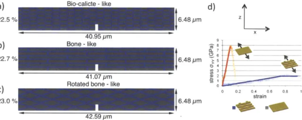
4.2.1 Topologies and Experimental Setup ... 40
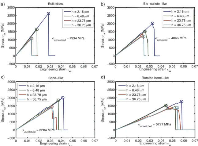
4 .3 M eth o d s... 4 1 4 .4 R esu lts ... 4 2 4.4.1 Ordered arrangement of nanoporous silica - Decreasing sensitivity to cracks 45 4.4.2 Introduction of weak links - stabilizing fracture ... 51
4.6 Conclusions... 55
5 Designing tougher composites by elucidating simple interactions between composite constituents ... 57
5.1 M aterials and M ethods... 58
5.2 Results... 62
5.3 Discussion... 72
6 From Computer Models to Synthesized Composites - Closing the Loop... 73
6.1 M aterials and M ethods... 74
6.1.1 Experim ental approach: Synthesis... 74
6.1.2 Experim ental approach: Fracture testing ... 75
6.1.3 M aterial properties of base m aterials ... 77
6.1.4 Computational m odeling... 77
6.2 Results... 80
6.2.1 Comparison of Computational Predictions with Experiment ... 80
6.2.2 Focus: experimentally observed fracture mechanisms ... 87
6.3 Conclusions and outlook... 92
7 Discussion and Conclusion... 94
8 Appendix... 105
8.1 List of figures... 105
List of journal publications:
1. L. S. Dimas, M. J. Buehler, "Influence of topology on mechanical properties of
bio-inspired silica-based hierarchical materials", Bioinspiration and Biomimetics, Vol. 7, paper # 036024 (2012)
2. L. S. Dimas, M. J. Buehler, "Tough and strong composites from simple building blocks", in review.
3. L. S. Dimas, G. H. Bratzel, I. Eylon, M. J. Buehler, "Tough Composites Inspired by
1 Introduction
Composite materials are commonly designed from building blocks with contrasting material properties with the goal of combining two attractive properties in one material system. A fundamental question in engineering composite materials for structural applications is how to design composites that effectively combine the properties of stiffness and toughness. Biologically mineralized composites such as bone, nacre, the frustules of diatom algae and deep-sea sponges are structural engineering wonders in this regard as they are assembled from simple building blocks and effectively combine high stiffness with high toughness and strength [1-10].
A large number of research efforts have focused on investigating the impressive
mechanical properties of biomineralized materials in light of their hierarchical nature [1, 10-20]. Amongst other things, these studies have introduced and elucidated the importance of the cooperativity of deformation mechanisms across arrays of length scales prevalent in natural hierarchical systems. Especially, in the context of fracture, a multiscale phenomenon [21], many natural toughening mechanisms are attributed to the hierarchy of structural features spanning length scales from the nanoscale to the macroscale [1, 10, 17, 22-25]. With the advancement of computational tools, in silica studies have also become a popular tool used to gain fundamental insight into the design principles employed by nature in developing advanced materials from primitive building blocks [26-31]. In [26] the authors utilized finite element models to support their arguments that the nanometer size of certain structural features in mineralized structures might be a conscious design mechanism employed by nature to optimize local flaw tolerance. They predict that there exists a certain length scale at which brittle materials become insensitive to flaws, thus enabling them to reach their theoretical strength irrespective of cracks or defects. Furthermore, in [30, 31] the authors used a multiscale modeling approach, informing mesoscale models with first principles derived full
atomistic data of silica to portray a direct correlation between increased toughening behavior and number of hierarchical levels in a diatom inspired system. Theoretical analyses have also proven very valuable to further elucidate the structure-property relationships of bio-composites with several contributions highlighting the essential role of large stiffness-ratios in reducing crack tip stress concentrations in lamellar structures
[32, 33].
Furthermore, a variety of other studies attribute the impressive combination of fracture toughness and stiffness exhibited by mineralized composites to other mechanisms. The more common and notable mechanisms cited include, but are not restricted to: energy dissipation and ductility through protein unfolding in the organic matrix phase [34, 35], and frictional dissipation due to shearing of mineral-organic interfaces [12, 36].
In addition to research efforts aimed at further understanding the fundaments of strength of these mineralized composites, significant attention in the materials science research community is devoted to developing manufacturing methods with the potential of synthesizing composites with equally impressive mechanical characteristics. Since its introduction in 1992 the layer-by-layer (LBL) templating technique has been widely used for this purpose [37-41]. In [39] technique was used to create an artificial nanostructured nacre replica with strength similar to natural nacre and Young's modulus similar to that of bone. While the technique permits a fine control of structural topologies at nano length-scales, it is correspondingly demanding to utilize the approach for manufacturing macroscale structures. The thickest nacre replicas produced in [39] were 4.9 ptm thick. Furthermore, self-assembly techniques have also received great interest and the diversity of systems attainable with these methods is truly remarkable [42-45]. In [42] DNA was assembled into three dimensional nanoscale shapes while the authors in [43] used a combination of mineralization and self-assembly to create a mineral-fiber composite with a structural configuration similar to that of bone. Looking forward, while both techniques are very powerful and have the potential for a precise control of structural features at very fine length-scales, to date neither of the methods provides an outlook for large-scale
cost-effective manufacturing of complex topologies, in particular at larger hierarchical length-scales.
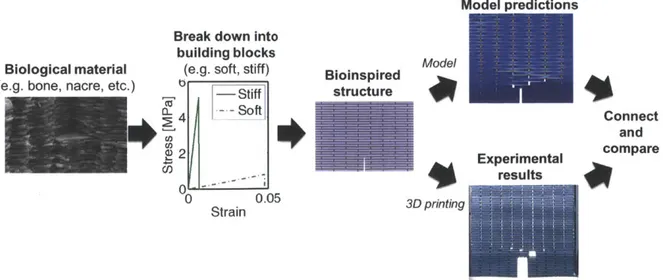
For many years, computers have proven an essential design tool for structural systems in the field of civil engineering. Model systems are typically conceived, subjected to the appropriate design loads and iterated upon in various computer software packages until satisfactory structural performance is obtained. Subsequently, detailed manufacturing orders are produced based on the iterated model systems and parts are assembled by separate manufacturers/contractors [46]. In this work a de novo complete design and synthesis approach for bio-inspired composites is proposed. Rigorous computational modeling providing fundamental insights into novel design principles for bio-inspired composites is followed by rapid manufacturing techniques producing composite structures with microscale structural features. The synthesized composites exhibiting fracture mechanical properties far superior to their individual constituents, with toughness moduli values up to 20 times than the individual constituents. Figure 1 displays the process flow of the work, from idea to design to model predictions and finally experimental results. Conclusively, the model predictions are compared with experimental results and possible improvements as well potential and impact of the methodology is discussed.
Model predictions
Break down into
building blocks
-Biological material (e.g. soft, stiff) Bioinspired Model
(e.g. bone, nacre, etc.) b Stiff structure
#
4 -4Soft Connect and 2 - compare
mL Zau
2Experimental - results 0 0.05 3D printing StrainFigure 1 Process flow of the approach used here. Starting from the simple model material building blocks
composites are built with bio-inspired topologies. The bio-inspired composites are manufactured with 3D printing and proceed to test the synthesized specimens. The results are compared to model predictions. Electron microscopy image of fractured nacre surface is reprinted from http://en.wikipedia.org/wiki/Nacre.
By looking beyond complex and highly species-specific structural features of
biomineralized materials, such as proteinaceous layers or mineral bridges, simpler interactions with key contributions to the superior stiffness, toughness and strength of biomineralized composites are identified. At some level, diatoms, bone, nacre and deep-sea sponges universally consist of more and less compliant regions arranged in specific geometries. It is hypothesized that ordering these softer and stiffer regions in specific geometrical arrangements is a powerful design principle for creating functional materials from inferior building blocks. In fact, in light of this principle it is expected that tuning and optimizing a confined number of simple geometric features of a single brittle material, e.g. silica, can produce superior materials. In Chapter 4 this hypothesis is rigorously explored with atomistically informed mesoscale spring bead models providing new insights into the influence of topological arrangement of softer and stiffer phases on the fracture mechanical response of composites.
Moreover, for a range of mineralized biological composites that combine toughness and strength, such as nacre, bone, dentin and enamel, the stiffness ratio between the stiff mineral phase and the softer organic phase is quite similar, despite the structures being composed of varying constituents [6, 47-50]. Based on these experimental findings a new hypothesis guiding further research into the fundamentals of toughness and strength of biomineralized composites is developed. Namely, the stiffness ratio, in the linear elastic regime of the constituents, controls the deformation and fracture mechanism of a composite. It is further hypothesized, that linearly elastic perfectly brittle interactions can be sufficient to lay the foundations of superior toughness in two-phase stiff bio-composite structures. A new triangular lattice spring bead model is developed, now intended to represent composites of constituents with 'minimal cost' constitutive behavior, i.e. the energy to fracture of the composite constituents is identical. Indeed, the studies show that tuning such simple constitutive behavior of the individual materials can optimize the interactions of the composite leading to fracture mechanical properties of the composites such as toughness modulus over eight times larger than for its building blocks, while retaining over 80% of the stiffness of its stiffest constituent.
Finally, to close the design loop and complete the leap from computational model to synthesized structure of bio-inspired composites, state of the art 3D printing technology is employed as a simple and effective rapid manufacturing technique to create physical artifacts of these computationally conceived systems with bio-inspired topologies. The synthesized composites exhibited structural properties similar to the presented computational systems and notably far superior to their constituents. Furthermore, the specific deformation and fracture mechanisms induced by the various topological arrangements in the experimental systems compared well to the corresponding mechanisms exhibited by the simulated composites. Moreover, key deformation mechanisms reminiscent of biomineralized structures were observed. The results indicate the possibility of designing materials in computers with tailored fracture mechanical properties and later realizing these structures with 3D printing.
2
Background
2.1 Nature as a source of inspiration
Through the course of history biological systems are continuously forced to optimize their design, in the context of their natural design constraints, to best persist the given environmental conditions [51]. Nature is an immense resource in terms of engineering know-how, a resource only accessible through thorough study. This has sparked the field of "Biomimicry" which in later years has assumed a very important role in a wide range
of research areas [9, 52-54]. Biomimicry is as termed by Benyus in [53] "... the
conscious emulation of life's genius. Innovation inspired by nature." Many impressive engineering feats can be directly attributed to a thorough study and emulation of 'life's genius' [55-57].
While nature certainly designs complex and advanced engineering systems with impressive performance, it is as noted by Mayer in [9] essential to view natural engineered systems in light of their design constraints. Typical biocomposites such as bone, the frustules of diatomaceous algae and nacre all likely consist of the same simple building blocks, minerals and proteinaceous organics, as these are the most abundantly available. Furthermore, as typical biological materials are assembled by self-assembly their structural design is a result of minimizing energetic cost while maximizing performance [58]. Due to limited resources in demanding environments the building blocks of natural systems are commonly very primitive as compared to the materials utilized in human engineered systems. Their careful assembly is more likely to be the product of evolutionary optimization and research efforts should be directed towards understanding this aspect of their design [9].
2.2 Mineralized materials and hierarchical structures
As of late mineralized materials have assumed an important role in the solid mechanics community with several research efforts highlighting the impressive mechanical characteristics of these structures [1, 4, 6, 7, 16, 47, 59]. Most generally, mineralized
materials are materials that are composed, fully or in part, of inorganic matter formed by mineralization, the process in which organic matter is transformed to inorganic matter. Furthermore the concept of hierarchical structures has gained increasing importance in the bioengineering community in the study of mechanical properties of biological materials [1, 5, 10, 60]. In the context of materials a hierarchical structure is one with an arrangement of structural features over a range of length scales. In the following sections mineralized materials, hierarchical structures and their impressive mechanical properties will be discussed in more depth.
2.2.1 Mineralized materials - ordering simple constituents in a tough composite
Mineralized natural materials are present in nature in a variety of forms and shapes, within the field of solid mechanics much attention has been devoted to the study of bone
[6, 12], mollusk shells [33, 61], deep sea sponges [1, 62] and the frustules of diatom algae
[2, 8, 63]. An intriguing feature of the mentioned materials, as is highlighted in the reference works, is the primitive building blocks from which they are assembled. These are minerals that are commonly very brittle and weak [1, 16, 64, 65] and organics, typically soft and weak and assembled to a larger part by clusters of simple hydrogen bonds [66-68]. Whilst the building blocks of these mineralized structures are simple, the architectural arrangements in which they are assembled are often highly advanced.
Nacre, also known as mother of pearl, is a biological composite found on the inner layer of mollusk shells such as oyster and abalone [64]. It shares structural characteristics with the nanoscale structure of bone [10] and sponge spicule of the deep-sea sponge
Euplectella sp. [1]. At a characteristic length scale all three of these biological
mineralized composites consist of stiff mineral platelets staggered in a soft organic matrix
[1, 69-73], a topological ordering similar to brick and mortar structures as seen in Figure
2. Whilst in bone this arrangement is predominant at the nanoscale in nacre and in sponge spicule it is observed at the microscale [1, 69].
a) b)
c)
Figure 2 (a) Schematic of the structure of bone showing plate-like crystals staggered in a collagen matrix.
Figure adapted from [71], with permission from Elsevier. (b) SEM micrograph showing the staggered arrangement of aragonite platelets in nacre. A small volume fraction of organic material forms the matrix phase connecting the platelets, bar = 2 pm. Figure adapted from [69], with permission from Elsevier. (c)
SEM image of a fracture spicule revealing an organic interlayer, bar = 1 pm. Figure adapted from [1], with from AAAS.
The platelets in the bone structure shown in Figure 2a are hydroxyapatite (HAp) mineral crystals, a ceramic, which are commonly known to be brittle and fracture catastrophically. The matrix phase is collagen constituting around 20 wt.% of the entire structure [74], whose mechanical properties have been studied by several groups [75, 76],
and as typical for a protein is soft and extensible. Similarly the platelets in nacre are formed by the brittle ceramic aragonite (CaCO3) whilst the matrix phase, constituting
here a mere 5 wt.% of the structure [64], again is formed of organics. Lastly, the mineral phase in the sponge spicule is composed of silica (SiO2), the fundamental building block
of sand and glass, and again these mineral platelets are separated with a few wt.% of weak organics [1, 62].
Experimental investigations has shown nacre to be an extremely fracture resistant material; its toughness modulus is 3000 times larger than the aragonite crystals it is mainly composed of and fracture toughness values as high as 8 MPa mi/ 2 have been
reported [3, 47, 77]. Similarly groups have reported fracture toughness's of bone around
7 MPa m1 12 [78, 79]. These values are quite astonishing keeping in mind the large wt. % of ceramics the bio-composites are composed of. Furthermore, the structures attain these impressive fracture resistances while retaining a considerable portion of stiffness from their mineral constituent. Values of Young's modulus exceeding 100 GPa have been reported for nacre [3].
Similarly experimental investigations of the mechanical properties of siliceous composites have revealed truly fascinating mechanical properties. Levi et. al. [80] reported results of mechanical testing on the spicules of Monorhaphis sponge showing the composite to exhibit an astonishing combination of properties. The silica-based spicules dissipated large amounts of energy upon fracture, exhibited considerable stiffness and were capable of undergoing large deformations reversibly. Other deep-sea sponges with impressive mechanical characteristics include the hexactinellid sponge
Euplectella aspergillum depicted in Figure 3a (the spicules of this this structure are also
depicted in Figure 2c) [1, 62]. Despite mainly being composed of the same building block as sand and glass these fascinating structures exhibit, as highlighted in the referenced work, advanced fracture toughening mechanisms such as crack blunting, crack deflection, crack arrest and stress delocalization.
In Figure 3b a variety of different structures of the silica frustules of diatom algae are pictured, exhibiting the great diversity among this class of organisms. Diatom algae are eukaryotic unicellular organisms that appear ubiquitously in aqueous environments, and they are the predominant contributors to bio-silica formation in the ocean. Despite being made primarily from this inferior building material, also the cell walls of alga exhibit mechanical properties characteristic of a highly advanced material with significant fracture toughness the main highlight as shown by recent experimental and computational work [2, 8, 27, 31, 65, 81, 82]. An interesting point to not here is that, where the structural features depicted in Figure 2 achieve a composite geometry with softer and stiffer regions by utilizing different building blocks the systems shown in Figure 3, attain a functional grading of material properties with a single building block by the use of
topology, porosity and nanoconfinement [1, 8, 81-83]. The different regions of the frustules of diatom algae show an astonishing variation of mechanical properties, Almqvist et. al. [2] reported elastic moduli varying over two orders of magnitude within the same siliceous frustule sample. Figure 3b clearly shows regions of varying density of porosity within the frustules thus implying a highly heterogeneous distribution of properties of within the algae cell walls.
a)
Figure 3 (a) Details of the Western Pacific hexactinellid sponge, Euplectella aspergillum, and its skeleton. (A) Illustration (from Schulze, 1887) of two preserved specimens, clearly showing the holdfast apparatuses,
the external ridge systems, and the terminal sieve plates. (B) Photograph of the underlying siliceous cylindrical skeletal lattice exposed by removal of the organic material. (C) At higher magnification, the square-grid architecture and regular ordering of the vertical and horizontal components of the skeletal system are clearly visible. Scale bars: A: 5 cm; B: 5 cm; C: 5mm. Figure reprinted from [62], with permission from Elsevier. (b) Images showing the broad diversity of diatom silica structures. (a) Bar = 1 ptm, (b) bar = 5 ptm, (c) bar = 10 ptm, (d) bar = 500 nm, (e) bar = 2 ptm, (f) bar = 10 ptm, (g) bar = 2 jim, (h) bar = 2 pm, (i) bar = 50 pim, (j) bar = 2 im, (k) bar = 1 pim, (1) bar = 10 jm. Figure reprinted from [81],
copyright C 2007, with permission from American Chemical Society.
topological assembly of mineralized structures. In fact, experimental investigations indicate that the specific architectural arrangements of the mineralized structures have been specialized for the environments the structures are exposed to. Diatoms of the type
Ellerbeckia arenaria residing in waterfalls resist continuous stress and are able to
undergo elastic deformation up to 33 % strain [84, 85] and deep-sea sponges anchored to the bottom of the ocean can also undergo large deformations without failing [1, 62]. 2.2.2 Hierarchical structures - assembling primitive building blocks at multiple
scales to advanced functional materials
Another key structural feature amongst mineralized biomaterials is the hierarchical structure they exhibit. The term hierarchy is here used in the sense it is described in [86], as an ordered set of interrelated subsystems where no authority relation is implied. In the comprehensive works by Fratzl et. al. [24] and Currey [23] hierarchies in biomineralized materials are thoroughly discussed. A truly fascinating aspect of the hierarchical nature of structures in nature is the range of length scales at which the subsystems exist. In spider silk for instance, hierarchy spans over nine orders of magnitude, from nanometers to meters [87]. Here the focus will be directed towards the hierarchical structure of four mineralized structures; human vertebrate bone, nacre, the hexactinellid sponge
Euplectella sp. and the cell walls from the diatom genus Coscinodiscus.
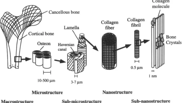
The hierarchical structure of both human vertebrate bone and the sponge Euplectalla sp. is well documented in the literature [1, 10]. Figure 4 indicates the six hierarchical levels of vertebrate bone as identified by Rho et. al. [10] and Figure 5 displays the eight hierarchical levels of the glass sponge Euplectalla sp. as identified by Aizenberg et. al.
Cancellous bone Lamella ortical bone Osteon Haversian canal H 10-500
stm
Microstructure Collagen molecule Collagen Collagen fiber fibril Bone Crystals 0.5 pm H I nm 3-7 pnm NanostructureMacrestructure Sub-microstructure Sub-nanostructure
Figure 4 Hierarchical structural organization of bone: (a) macrostructure: cortical and cancellous bone; (b) microstructure: osteons with Haversian systems; (c) sub-microstructure: lamellae; (d) nanostructure: collagen fiber assemblies of collagen fibrils; (e) sub-nanostructure: bone mineral crystals, collagen molecules, and non-collagenous proteins. Figure reprinted from [10], with permission of Elsevier.
Figure 5 Hierarchical structure of Euplectella sp. (A) Image of the entire structure, indicating cylindrical glass cage. Scale bar: 1 cm. (B) Close up of the cage structure portraying two square-grid lattices super imposed on each other at angled orientations. The arrows indicate stabilizing orthogonal ridges. Scale bar: 5 mm. (C) SEM image showing how each strut (enclosed by a bracket) is composed of a bundle of multiple spicules (arrow indicates the long axis of the skeletal lattice). Scale bar: 100 im. (D) SEM image showing the ceramic fiber-composite nature of a fractured and partially HF-etched single beam. Scale bar: 20 pim.
(E) SEM image showing the cemented nature of the HF-etched junction area. Scale bar: 25 pim. (F)
Contrast-enhanced SEM image of showing a cross section of a spicular strut. The micrograph reveals the large variety of sizes of spicule surrounded by a laminated silica matrix. Scale bar: 10 pim. (G) SEM image of a spicule cross section, revealing the laminated structure. Scale bar: 5 gm. (H) SEM of a fractured spicule, revealing an organic interlayer. Scale bar: 1 pim. (I) Bleaching of biosilica surface revealing its consolidated nanoparticulate nature (25). Scale bar: 500 nm. Figure reprinted from [1], with permission of
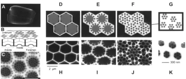
AE F G *099 Go* .00 Areola Foremen -300 r 2 pn I J K
Figure 6 (A) SEM image of a silica shell (Coscinodiscus sp.). (B) Schematic showing the structural set-up
of the valve. (C) High-resolution SEM images of a valve seen in planar view from below (areolae, cribra, and cribella) from Coscinodiscus radiatus. Scale bar: 2.5 mm. (D) to (G) shows a schematic drawing of the templating mechanism by the phase separation model proposed in [19]. (E) to (H) show SEM images of C.
wailesii valves in the nascent state. (D) The monolayer of polyamine-containing droplets in close-packed
arrangement within the SDV guides silica deposition. (E and F) Consecutive segregations of smaller (about
300 nm) droplets open new routes for silica precipitation. (G) Dispersion of 300-nm droplets into 50-nm
droplets guides the final stage of silica deposition. Silica precipitation occurs only within the water phase (white areas). The repeated phase separations produce a hierarchy of self-similar patterns. Figure reprinted from [19], with permission of AAAS.
Further, although not as comprehensively described, the siliceous frustules of diatom algae also exhibit magnificent hierarchical structuring [19, 88]. Specifically, diatoms of
the Coscinodiscus genus exhibit extraordinary silica patterning, with finely patterned
arrangements of pores ranging in diameter from under 50 nm to more than 1.600 gm
[82]. In [19] Sumper presents the hierarchical structure of the Coscinodiscus as the
self-similar silica porous patterns as shown in Figure 6. As illustrated through the figures and described in [19] the hierarchy originates from the walls of the honeycomb-like areola structure of the valve and consists of deposited silica in self-similar porous patterns of decreasing diameter. AFM imaging has further revealed that the siliceous layers are composed of silica nanoparticles, similar as for the glass sponge, thus constituting the
up un c ax
Lie 11 1
Figure 7 Hierarchically organized structure of the nacreous layer of the Japanese pearl Pinctadafuctata. a) FESEM image of the highest level of hierarchy. Scale bar: 1 ptm. b) FESEM image of the second
hierarchical level. Scale bare: 100 nm. c) FETEM image of the lowest level of hierarchy, the nano building block. Scale bar: 10 nm. Panels d) to f) show corresponding schematic drawings of the three levels of hierarchy. Figure adapted from [14], with permission of WILEY-VCH.
The fourth discussed biomineralized structure, nacre, also has a characteristic hierarchical nature; this is also a system that has been studied by several research groups, [14, 17, 18,
90]. The hierarchical structure of the nacreous layers of Japanese pearl Pinctadafuctata
is presented [14]. Three distinct levels of hierarchy are shown in Figure 7, SEM images are presented in Figure 7a-c while Figure 7d-f show the corresponding schematic drawings. The hierarchical organization is seen to resemble a self-similar structure with the brick and mortar structure of aragonite platelets and organic interlayers repeated at progressively smaller scales from the microscale to the nanoscale over. almost three orders of magnitude.
In Table 1 the various hierarchical levels of the structures introduced above are presented and summarized in an organized fashion.
Table 1 Tabular representation of the subsystems of the hierarchical structure of the four
biomineralized materials; human vertebrate bone, the hexactinellid sponge Euplectella sp., the siliceous frustule of the diatom algae genus Coscinodiscus and the nacreous layers of the Japanese pearl Pinctadafuctata.
Level of Characteristic Human Eupylecte//a Cosciodiscus Pinclada
hierarchy eghsae vrert bon apri//um sp. (diatom fueratta
(deep-sea algae) (niacre) sponge) I I 1 I nm Collagen - HAp composite Silica nanoparticles Silica nanoparticles
2 ~10nm - Porous structure Nano
in cribellum building layer block hexagonal aragonite platelets (tier 3)
3 100 nm Collagen fibril - Porous structure
-in cribrum layer
4 1 gim Collagen fiber Laminated Areola Composite
structure of honeycomb of nano
silica and structure building
organic block and
interlayer organic
matrix (tier 2)
5 - 10 pm Lamellae Silica beams Nacreous
structured as structure
ceramic-fiber (tier 1)
composites
6 - 100 pm Osteon with Bundle of
Haversian spicules form
system struts
7 - 1 mm - Cage structure Diatom frustule
with two structure superimposed
square grid lattices
8 I cm 1 Cortical and Hexactinellid cancellous bone sponge structure
3
Methods
The hierarchical multiscale nature of biological materials spanning from the individual protein molecules at the nanoscale to precise the precise topological arrangement of bundles of spicules at the macroscale makes computational methods very appealing tools for their study. In silica studies allows access to all scales, notable also the atomistic scale, which cannot be effectively probed experimentally. While the last chapter of this thesis includes experimental work the main part of this work consists of computational investigations and thus that will be the focus of this methods chapter. Methods and models will be introduced and put into context here, while their detailed design tailored for the individual studies will be outlined in the accompanying chapters. Details on the manufacturing methods are given in this chapter while the details on the experimental testing are given in Chapter 6.
3.1 Modeling mesoscale structures - spring bead models
As was outlined in Chapter 2, biomineralized materials exhibit intricate topological arrangements of softer and stiffer phases at the mesoscale. It is hypothesized here that these topological arrangements are of prime importance to the superior fracture mechanical properties exhibited by biomineralized composites and thus naturally the mesoscale plays an important role in this work. Indeed, appropriate modeling must be suitable for studying fundamental concepts of fracture at this this intermediate scale. In this work discrete lattice models are used to study mesoscale design principles of biocomposites. A schematic of a triangular lattice spring bead system is shown in Figure
Figure 8 Schematic overview of a spring bead triangular lattice system. The lattice is two-dimensional,
matter is represented by discrete beads and the beads are connected to their nearest neighbors by springs.
Discrete lattice modeling techniques have been used widely for the study of fracture at meso length scales and have been validated by several independent research efforts
[91-93]. This class of model received much attention in the late 1980's when used extensively
to study the influence of randomness and disorder on the fracture behavior of various materials [94-96]. Further, in [91] in the context of fracture mechanics, triangular lattice spring bead models were shown to reproduce numerical continuum mechanical solutions for stress intensity factors in various systems. In the class of spring bead models employed here, springs, the bonds between the beads, are allowed to break if they extend beyond some critical length, rc. This represents the initiation or growth of a crack and the system will fail if a crack, the breaking of bonds, percolates through the network. Two key features make this class of models attractive for use here. First of all, cracks are represented in a very intuitive way, simply as the breaking of bonds. Moreover, no explicit crack propagation criteria is required, this follows naturally as the breaking of bonds. These properties of the spring bead system provide significant advantageous over conventional finite element methods were the propagation of cracks is a far more complex matter. Furthermore, despite their apparent simplicity triangular lattice spring bead models have a documented agreement with and good representation of continuum fracture mechanics concepts.
The respective phases of the investigated composites are modeled as homogeneous and thus the systems studied could be characterized as represented by an ordered heterogeneity. Similarly to the representations in [94-96] the beads represent a group of smaller particles/molecules, however in the current system the beads are assumed to be
large enough to neglect intrinsic disordered heterogeneity.
3.2 Material model - starting from bulk and nanoporous silica
Initially the goal is to show that tough composites can be assembled from the most brittle of building blocks simply by utilizing geometries as an active design tool. Thus the mesoscale model is informed with first principles derived full atomistic data on the constitutive behavior of two distinct forms of silica (the fundamental constituent of glass), bulk silica and nanoporous silica. This specific coarse-grained model is developed in [30] and is based on the atomistic simulations described in [97]. Excerpts of the results of this study are presented in Figure 9 showing the contrasting stress strain response of bulk silica and a nanoporous silica sample. The nanoconfinement of the silica structure induces a compliant and ductile response.
9
CU)
CL 7
-
6-5
b
4
CO
3-0
0
0.2
0.4
0.6
0.8
1
strain
Figure 9 (a) ReaxFF derived stress-strain response for two of the tested geometries in [97], bulk silica and
nanoporous silica with sidewall thickness w of 17 A. Solid lines indicate lines of best fit. Figure adapted from [97] and reprinted with permission from the Nature Publishing Group.
The constitutive behavior displayed in Figure 9 is used to train the discrete particle lattice system shown in Figure 8 by application of the Cauchy-Born rule [30, 98, 99]. Further, to ensure a separation of scales between the atomistic simulations and the mesoscale simulations the equilibrium spacing between particles in Figure 8 was chosen to be 78
nm. Thus a mesoscale model was developed, containing first principles based full atomistic information, capable of simulating micrometer length scales. Once the influence of topologies has been extensively studied, new material models are designed and utilized in this work to explore further research questions. These are treated separately in the corresponding chapters.
As the models presented in this work are meant designed to highlight individual fundamental design mechanisms it is imperative that they are simple. Several interesting studies on mineralized structures attribute toughening mechanisms to interfacial sliding effects occurring at the interface of soft organics and the brittle mineral crystals [100]. However, this mechanism is not a focus in this work and thus the models are designed such as to exclude this effect. Therefore the adhesion at the interfaces of the system between the bulk and nanoporous silica (for the primary study and between the corresponding model materials for the subsequent studies) is chosen to be perfect. This implies that the interface is as strong as the weakest phase, thus excluding interfacial failure as an additional toughening mechanism.
3.3 Measuring stress in a discrete system
Traditionally, stress has been most commonly utilized as a measure of loading in a continuous system. The Euler-Cauchy stress principle states,
"Upon any surface (real or imaginary) that divides the body, the action of one part of the body on the other is equivalent (equipollent) to the system of
distributed forces and couples on the surface dividing the body."
The internal forces across such a real or imaginary surface normalized by the area of said surface are exactly equal to the average of the internal stresses acting over said surface. As surfaces are more easily envisioned in continuous systems, the notion of stress is also more intuitive in regards to continuous matter. However, with the increased use of molecular dynamics accompanied by the larger focus on the nanoscale, discrete systems are becoming more commonplace. Moreover, along with the ambition to couple and exchange information between discrete systems and continuous systems, stress measures
have become an important concept also in particle mechanics. Specifically, focus has been directed towards developing a formulation of stress in a discrete system that can be proven equivalent to a continuous stress measure. To this end, the virial stress measure introduced by Tsai [101] has proven to be of great use.
3.3.1 The virial theorem and the virial stress
Initially introduced by Clausius in 1870 the virial theorem provided a link between the pressure and the potential energy of a homogenous discrete particle system in equilibrium. Over one hundred years later, in 1978 Tsai showed that identical results for the pressure calculation could be achieved by analyzing a stress like quantity that was subsequently termed the virial stress [101]. The measure introduced has a simple interpretation, which will be outlined below, and is understood neatly in connection with the conventional continuum Cauchy stress.
In this presentation of the virial stress it will be introduced as the superposition of two distinct terms and is thus written as
ojg = oij, + oij,2. (1)
The individual terms are due to distinct interactions and are more easily conceived separately. Figure 10 shows a cartoon of an imaginary surface across which particles interact and the virial stress is evaluated.
C C
B
Figure 10 Schematic indicating two particles, a and P, interacting across an imaginary surface CC' at
The first of the two contributions to the virial stress, agg11, is the static equilibrium term derived from the virial theorem by Clausius. This contribution accounts for the forces acting between atoms across a certain surface and is expressed as follows
1 B#(d(r) ri
i1 = 2V
L
Or) ri - (2)a,fl,a:#fl
Here, V denotes the volume of the considered atomistic system, Greek letters alpha and beta are used to indicate atoms, subscript Roman letters are used to indicate the coordinate direction,
P
represents the interatomic potential and r indicates the radial distance from the center of mass of an atom. In a system in equilibrium such as the one analyzed by Clausius, where the mean velocity of the ensemble of particles is zero, this term fully accounts for the system pressure.The second contribution to the virial stress comes in to effect in non-equilibrium systems, systems experiencing a net force. Specifically, in connection with the schematic in Figure
10 this term accounts for the forces exerted across the surface CC' due to momentum flux imparted by particles crossing the boundary and it is expressed as
=7j
2 VL 1~~vv
(3)
a
Here, m(") denotes the mass of atom a while v ") is the velocity of atom a in the i coordinate direction relative to the mean velocity of the body.
This last kinetic term has caused controversy in the community and in [102] it was claimed that this term could in certain systems create negative stresses and was in fact non-physical as a contribution to a stress measure in a discrete system. Subsequent research efforts presented arguments claiming to disprove this view and in support of the virial stress as a stress measure equivalent to the continuum Cauchy stress [103, 104]. Furthermore, [103] computational simulations on full atomistic models were conducted supporting the virial stress as a discrete equivalent to the Cauchy stress. By regarding the kinetic term of the virial measure in the light in which it was presented here, as a momentum flux term, it is readily realized that this term is necessary to account for all force interactions across boundaries in the system. Moreover, it makes perfect physical
sense in a system were particles have non-zero velocities relative to the ensemble velocity of the system. It is further noted that the virial stress converges to the continuum measure only when averaged in space, hence only in microscopically large systems.
3.4 Strain measures for discrete lattices
As well as measuring local stresses in a discrete system it is desirable to be able to measure and track the local variations of local strain in a discrete system. Characterizing strains can provide many insights and educate about mechanisms occurring at the atomistic scale. Further, in order to have an effective framework in which the atomistic scale can be coupled with the continuum scale it is essential to have a consistent measure of strain that can create a bridge between the two approaches.
Two different descriptions of strains for discrete particle systems are presented in the following subsections. The descriptions are accompanied by examples and some discussion of their respective advantages and disadvantages. It is noted that the presented measures are, with certain exceptions (to be clarified), valid for general discrete systems, both atomistic and coarse-grained particle systems alike.
3.4.1 An atomistic deformation gradient
In continuum mechanics deformation is conventionally characterized by relating the current configuration of a body to its reference configuration [105, 106]. The location of a point on a body in the undeformed configuration is typically denoted by an
uppercase X = tX1, X2, X3} while the location of the same point in the deformed
configuration is denoted by x = {x1, x 2, x3}. The deformation can thus be characterized
by relating the location of a point in the two different configurations through a mapping
x = x(X, t). The derivative of this mapping with respect to the undeformed configuration
is called the deformation gradient, F = alX(4)
The deformation gradient in turn, serves as the basis of many strain measures [107]. In the past ten or so years several groups have approached the challenge of defining a continuum compatible atomistic strain by defining an atomistic deformation gradient, two of these groups arrived at very similar results [108, 109]. The expression developed by
Zimmerman and coworkers in [109] will be the one presented here. Further, the strain developed through this method will be subsequently termed the virial strain.
By assuming small displacements, including only the linear term in the Taylor expansion
of the deformation gradient, and noting that the smallest measurable distance in the system is the distance to a neighboring atom, the equation for the deformation gradient in discrete system can be rewritten as
-F. -Xap = 0 (5)
Here xaf and Xap represent the distance between atom a and
fl
in the deformed and reference configuration for coordinate direction i andj
respectively. It is noted in [109] that this relation can only hold exactly for a single neighbor of a particular atom, thus it is required that the sum of squares of the errors for all neighboring atoms is a minimum. Further, performing some algebra on the least squares expression the following expression for the deformation gradient is obtainedF-q = ok(,") - (6) where n o1 = x X" , (7) p=1 and n 7IjM = Xa XM. (8) pg=1
Here n represents the number of nearest neighbors of the atom in question and again Greek letters indicate atoms while Roman letters indicate coordinate directions.
While this expression only considers displacements relative to nearest neighbors the expression developed by Horstemeyer and coworkers [108] also considers displacements relative to particles that are not nearest neighbors. The contribution of these displacements is controlled by the introduction of a weighing function that commonly decreases as more distant neighbors are considered. The formulation derived by Zimmerman et. al. can be viewed as a special case of that derived by Horstemeyer et. al.
L
L
I
where the weighing function is unity for nearest neighbors and vanishes for all other neighbors.
The functional form of weighting functions and cut-off radius affect the value of the computed strain and especially has an influence near strain localizations [110]. In the form in which it is presented here the deformation gradient has been shown to comply with the essential compatibility requirements enforced through continuum mechanics
[109].
3.4.2 Moving least squares fit to displacement field
In an effort to create a framework for analyzing coupled atomistic-continuum systems Belytschko and coworkers developed what they termed a moving least squares (MLS) approximation to the displacement field in discrete systems [111, 112]. In short, the MLS scheme creates a continuous displacement field by interpolating the displacements of particles. With an appropriate finite difference scheme the displacement field can be utilized to compute an appropriate deformation gradient and any desired strain measure. The method will be presented in brevity below in accordance with its presentation in [112].
With the MLS approximation the displacement at any point x is described by the continuous function
m
u(x) =
pi(x)a(x).
(9)Here m is the number of basis functions pi (x) and a (x) are vector coefficients computed from the moving least squares approximation, to be described below. This form of expressing the displacement is similar to the methodology in continuum finite element methods; the basis functions pi (x) can be regarded as equivalent to interpolation functions in FEM. The polynomial order of the basis functions is chosen based on desired order of the displacement function. The vector coefficients ai (x) are found by minimizing the weighted L2-norm, q(x), of the displacement field u(x) and is given by
q(x) = . (pi (xa)aj (x) - ua)T wmis X
ae(-sx (10)
- X)
(P
(xa) ay (x -Ua)-In this expression a sum is implied over the repeated indices i and
j,
the total summation is performed for all atoms within the support Sx and wms (xa - x) is a weight function over the support region. The weight functions can assume many different forms and have a significant impact on the performance of the solution field, in general they should have large values close to the treated atom at point x and smaller values for points further away. The support region is the region over which relative displacements are considered for a given atom and its size is commonly be tailored depending on the application [111].3.4.3 Virial strain vs. MLS approximation - derivation and discussion
Now the respective methods for evaluating strain are tested, discussed and compared. First, however the expressions must be developed from the equations presented earlier. 3.4.3.1 Derivation of expressions
Starting with the virial strain, appropriate algebraic manipulation of the deformation gradient leads to the following convenient expression for the left Cauchy Green tensor B = FF T for atom a
1 N Axa p
B9,= L Kr2J (11)
pl=1
Here N indicates the number of nearest neighbors and Axa - x -x and axf=
xf -x with xf signifying the i-th component of the coordinates of atom a in the
deformed configuration. Further, ro is the equilibrium spacing of the lattice and A a prefactor depending on the specific lattice chosen. For the employed triangular lattice with only nearest neighbor interactions it is given in [109] that A = 3. It is noted that the
left Cauchy-Green tensor is conveniently expressed solely in terms of the current positions of particles in contrast to the more involved expression for the deformation gradient F as presented earlier.
E = VB - 1. (12) Here, 1 is the identity tensor and the square root of B is well defined in terms of its eigenvalues and eigenvectors, as it is a symmetric positive definite matrix
3
NIB = f e;@eg, (13)
where
and wi and ei are the eigenvalues and eigenvectors of the left Cauchy-Green tensor, respectively.
As for the description of strain through the MLS-approximation of the displacement field the employed weight functions wm1s are first presented. These weight functions are the same as those suggested in [112] and are expressed as
21 1 2 4r2 + 4r3 for r -r32 (15) = 44 1 - 4r + 4r2 _ _r3 for- < r 1, 3 3 2 0 for r > 1.
Here r is naturally the radial distance from the center atom. It is readily recognized that the given functional expression fulfills the requirements as outlined above. Further, linear basis functions are implemented and the support is restricted to four times the nearest neighbor distance as also suggested in [112]. Again an engineering strain measure is employed to characterize the strain field and the following familiar expressions are retrieved
aux
auz
E = Ezz > ;EXZ
(aux
+au)
(16)2 ay ax)(6
The derivatives are evaluated numerically with central differences as shown below for
aUx I XX=xi+l - UxIx=xi-l
ax
Ix=x, 2 -h3.4.3.2 Discussion
The test case that is used is a linear elastic model material, with and without a notch, subjected to pure longitudinal tension. The resulting longitudinal strain field plots are plotted with MATLAB and presented in Figure 11. As expected the longitudinal strain field is perfectly uniform with both descriptions for the unnotched case. Furthermore, both strain descriptions correctly allow the formation of a strain concentration around the crack tip in the notched case. Moreover, inspecting the respective coloring a very good quantitative correspondence is observed for the two descriptions. Now that the correspondence for this test case has been documented some details of the implementation of the two approaches are discussed.
E - MLS E - Virial a) Unnotched 0.01 b) Unnotched 0.01 0.008 0.008 0.006 0.006 C) Notched .0 Notched 0.004 0.004 0.002 0.002 0 0
Figure 11 Comparison of longitudinal strain fields from the MLS and virial description. a) MLS derived
strain field for unnotched case, b) virial strain field for unnotched case, c) MLS derived strain field for notched case, d) virial strain field for notched case. The field plots show very good agreement indicating that the MLS description of displacements and virial strain agree well in terms of longitudinal strain.
The main difference between the two methods for the tested case lies in the
computational effort. The virial strain description only considers the positions of nearest neighbors and thus the strain field is computed far more efficiently with this method. Reducing the size of the support region in the MLS-approximation to the displacement field can reduce the computing time significantly; however, it does this at the expense of the stability of the approximations. Support regions with radii of less than three lattice
spacing's commonly lead to expressions with ill-conditioned matrices. Albeit
analysis of systems with discontinuities such as surface boundaries, material interfaces and cracks. The MLS-method is not constrained to systems with specific configurations or lattice structures and the support region can be tailored such as to express the displacement field around any particular particle surround by a host of discontinuities in a robust manner. For systems more involved than the one presented here, e.g. an amorphous solid, it is clear that the virial strain as derived by Zimmerman in [109] would be inapplicable whereas the MLS-approximation to the displacement field remains
4 Designing tough composites from simple
building blocks with bio-inspired topologies
The previous discussion of bio-mineralized materials highlighted the heterogeneous distribution of their mechanical properties. Moreover, several examples were given illustrating careful arrangements of regions with distinct constitutive behavior in complex architectures. As studies of a variety of bio-mineralized structures has revealed these characteristics to be common for a range of biological mineralized materials in different environments it is interesting from a materials scientist's and structural engineers point of view to study these features in light of them being advanced design principles. Computational investigations at the micro-scale gain novel insights into the mechanics of bio inspired composites.
4.1 Introduction
An intriguing characteristic of some well-studied mineralized materials such as nacre, bone, frustules of diatom algae and deep-sea sponges, is that they all, at some length scale, are composite materials consisting of stiff, less extensible regions and soft, deformable regions. The hypothesis to be explored here is that that ordering these softer and stiffer regions in specific geometrical arrangements is a powerful design principle for creating functional materials from inferior building blocks.
This study shows that the inclusion of a deformable nanoconfined silica phase in bulk silica structures can be sufficient if introduced and distributed in an appropriate manner.
By studying the mechanisms of deformation and failure of model materials insights are
gained in the detailed mechanisms by which deformable and brittle regions interact to form a fracture resistant composite, and which details of their structural configuration make their interaction advantageous for meso- and macroscale structures. Finally it is argued that the compliance of the second phase is the key attribute enhancing the overall


![Figure 9 (a) ReaxFF derived stress-strain response for two of the tested geometries in [97], bulk silica and nanoporous silica with sidewall thickness w of 17 A](https://thumb-eu.123doks.com/thumbv2/123doknet/14160067.473120/27.918.150.744.486.867/figure-reaxff-derived-response-geometries-nanoporous-sidewall-thickness.webp)