Publisher’s version / Version de l'éditeur:
Vous avez des questions? Nous pouvons vous aider. Pour communiquer directement avec un auteur, consultez la
première page de la revue dans laquelle son article a été publié afin de trouver ses coordonnées. Si vous n’arrivez pas à les repérer, communiquez avec nous à PublicationsArchive-ArchivesPublications@nrc-cnrc.gc.ca.
Questions? Contact the NRC Publications Archive team at
PublicationsArchive-ArchivesPublications@nrc-cnrc.gc.ca. If you wish to email the authors directly, please see the first page of the publication for their contact information.
https://publications-cnrc.canada.ca/fra/droits
L’accès à ce site Web et l’utilisation de son contenu sont assujettis aux conditions présentées dans le site LISEZ CES CONDITIONS ATTENTIVEMENT AVANT D’UTILISER CE SITE WEB.
Interflam 2010, 12th International Conference on Fire Science & Engineering
Conference [Proceedings], pp. 1-6, 2010-07-05
READ THESE TERMS AND CONDITIONS CAREFULLY BEFORE USING THIS WEBSITE. https://nrc-publications.canada.ca/eng/copyright
NRC Publications Archive Record / Notice des Archives des publications du CNRC :
https://nrc-publications.canada.ca/eng/view/object/?id=b002f1f8-4c8f-4faf-8eb8-a2d6eaec85ec https://publications-cnrc.canada.ca/fra/voir/objet/?id=b002f1f8-4c8f-4faf-8eb8-a2d6eaec85ec
NRC Publications Archive
Archives des publications du CNRC
This publication could be one of several versions: author’s original, accepted manuscript or the publisher’s version. / La version de cette publication peut être l’une des suivantes : la version prépublication de l’auteur, la version acceptée du manuscrit ou la version de l’éditeur.
Access and use of this website and the material on it are subject to the Terms and Conditions set forth at
Comparison of gypsum board fall-off in wall and floor assemblies
exposed to furnace heat
http://www.nrc-cnrc.gc.ca/irc
Com pa rison of gypsum boa rd fa ll-off in w a ll a nd floor a sse m blie s
e x pose d t o furna c e he a t
N R C C - 5 0 8 4 3
S u l t a n , M . A .
J u l y 2 0 1 0
A version of this document is published in / Une version de ce document se trouve dans:
Interflam 2010, 12th International Conference on Fire Science & Engineering
Conference, Nottingham, UK, July 5-7, 2010, pp. 1-6
The material in this document is covered by the provisions of the Copyright Act, by Canadian laws, policies, regulations and international agreements. Such provisions serve to identify the information source and, in specific instances, to prohibit reproduction of materials without written permission. For more information visit http://laws.justice.gc.ca/en/showtdm/cs/C-42
Les renseignements dans ce document sont protégés par la Loi sur le droit d'auteur, par les lois, les politiques et les règlements du Canada et des accords internationaux. Ces dispositions permettent d'identifier la source de l'information et, dans certains cas, d'interdire la copie de documents sans permission écrite. Pour obtenir de plus amples renseignements : http://lois.justice.gc.ca/fr/showtdm/cs/C-42
Comparison of Gypsum Board Fall-Off in Wall and Floor
Assemblies Exposed to Furnace Heat
Mohamed A. Sultan Fire Research Program Institute for Research in Construction National Research Council of Canada Ottawa, Ontario, Canada K1A 0R6
mohamed.sultan@nrc.gc.ca
ABSTRACT
This paper presents and discusses the results of 41 full-scale wall fire resistance tests conducted at the National Research Council of Canada, in accordance with ULC-S101 standard fire exposure, to determine a gypsum board fall-off temperature criterion. The tests used assemblies with wood and steel studs protected with either one or two layers of Type X gypsum board and with or without insulation (glass, rock and cellulose fibre) in the wall cavity. The proposed temperature criterion for the gypsum board fall-off in assemblies with board installed vertically in a wall furnace is based on the sudden temperature rise measured on the back side of the fire-exposed gypsum board which is caused by either the board falling-off or sagging. A comparison, for wall assemblies, of the predicted time for the gypsum board fall-off using the sudden temperature rise and the observed time from video cameras is provided. A further comparison, using the temperature criterion, of Type X gypsum board fall-off when the board is installed vertically (wall assemblies) and horizontally (floor assemblies) is presented.
INTRODUCTION
With the advent of performance-based codes and performance-based fire safety design options, fire resistance models become important tools to aid their use. Currently, major fire safety research efforts are being invested globally into developing numerical models that can be used by designers to facilitate the use these of performance-based options. Development of such models faces several challenges, such as the availability of reliable data on the thermal and mechanical properties of materials, as well as, information on the performance of building materials at elevated temperatures. For example, in lightweight frame construction, one important limitation of the existing models is the prediction of the point of gypsum board fall-off, which significantly impacts structural fire resistance predictions. Studies1,2,3,4,5 carried out at the National Research Council of Canada on a large number of full-scale lightweight framed wall and floor assemblies have shown that gypsum board provides significant fire resistance protection to framing.
Fire resistance models typically consist of a thermal model and a structural model. The thermal model calculates the temperature history of the assembly’s components and feeds these temperatures to the structural model to determine the thermal and structural properties at a given time and temperature, which are then used for calculating the structural response of the assembly. In calculating the temperature history, it is essential to determine how long the gypsum board will stay in place to protect the frame. This can be determined either by using the observed time of gypsum board fall-off from fire resistance tests or, alternatively, by the temperature at which the gypsum board will likely fall-off when exposed to heat. Due to the difficulty in predicting gypsum board fall-off times for assemblies with configurations that have not been tested, a time failure criterion is impractical for use in numerical modeling. A recent study6 on the gypsum board fall off in 80 full-scale floor assemblies was carried out. The floor assemblies were constructed with solid wood joists, wood I-joists, steel C-joists and wood trusses using one or two layers of Type X gypsum board ceiling finishes, and with and without insulation in floor cavities and resilient channels. In that study, four different approaches for determining the fall-off of gypsum board in
floor assemblies (horizontal orientation) were explored. The first approach was based on the average temperature recorded at the time of fall-off during fire resistance tests of the first piece, and at the time of fall-off of the last piece of each gypsum board layer. The second approach used the average of the first and last piece fall-off temperature criteria determined in the first approach. The gypsum board temperature corresponding to the average of the first and last piece fall-off times was used to estimate the average fall-off temperature in the third attempt. The last method dealt with individual temperature histories and looked at the sudden increase in temperature caused by gypsum board fall-off. After comparing the results obtained using all approaches, the sudden rise in temperature criteria was the preferred approach. This approach was also used in this study to determine the temperature criteria for the gypsum board fall-off in assemblies tested in the wall furnace, vertical orientation. Comparison of the gypsum board fall-off time based on the sudden temperature rise and the observed time from the video cameras is provided. A comparison of the temperature criteria for gypsum board fall-off in both vertical and horizontal orientation is also provided.
The objective of this study was to establish a temperature criterion for the gypsum board fall-off that can be used by the modelers to improve the accuracy of their fire resistance models to assess the performance for lightweight wall and floor assemblies.
DESCRIPTION OF TESTS Test Assemblies
Forty-one wall assemblies of solid wood or steel studs framing 3.6 m wide by 3 m high were constructed in accordance with CAN/CSA-A82.31-M917 to investigate the effect of a number of parameters on the assemblies fire resistance performance. The perameters studied included resilient channels, spaced either 406 mm o.c. or 610 mm o.c., which were installed between the gypsum board and framing for sound reduction purposes. These resilient channels, 14 mm deep by 58 mm wide, were fabricated from 0.6 mm thick galvanized steel sheets. The channels had a 34 mm wide web, designed to support the gypsum board connection, and one 18 mm wide flattened flange lip connected to the bottom of the joists or trusses. Three types of insulation were used: glass and rock fibre batts, a cellulose fibre insulation either sprayed wet and then allowed to dry to achieve an 11% moisture content, or dry blown in the wall cavities. The glass, rock and cellulose insulation satisfied CSA A101-M838, CAN/ULC S702-M979 and CGSB 51.60-M9010 standards, respectively. The wall finish used in the assemblies was Type X gypsum board, 12.7 mm or 15.9 mm thick, and met the standard requirements of Type X gypsum board11,12. The gypsum boards had an average surface density of 9.85 kg/m2 for a nominal 12.7 mm thick board and 10.5 kg/m2 for a nominal 15.9 mm thick board. These were attached perpendicular, either to resilient channels or directly to the stud framing. Complete construction details of the tested assemblies can be found in Reference 3.
Instrumentation
In addition to the standard instrumentation specified in CAN/ULC-S101-M8913, numerous thermocouples (over 100) were placed within each wall assembly in order to obtain temperature histories at various locations. Details on the locations of the thermocouples can be found in Reference 3.
Test Condition and Procedure
The assembly’s gypsum board finish was exposed to heat in a propane-fired vertical furnace in accordance with CAN/ULC-S101-M8913, “Standard Methods of Fire Endurance Tests of Building Construction and Materials”. The furnace temperature was measured by nine (20 gauge) shielded thermocouples and the average of these thermocouples was used to control the furnace temperature in such a way that it followed, as closely as possible, the CAN/ULC-S101-M89 standard temperature-time curve.
Gypsum Board Fall-Off Time
Two video cameras which can record approximately 75% of the gypsum board fire exposed-side surface area were used only in 26 out of 41 tests (15 tests carried out prior to the installation of video cameras) to record the gypsum board performance during the fire resistance tests. The gypsum board fall-off time was determined from the recorded video camera tapes.
RESULTS AND DISCUSSION
Roy-Poirier and Sultan6 found that an effective way to determine the fall-off temperature of gypsum board in 80 floor assemblies was to take the last temperature before the sudden temperature rise for individual thermocouples on the back-side of the fire-exposed gypsum board. This approach is also used in this study to determine the fall-off temperature for gypsum board in wall assemblies.
To determine the gypsum board fall-off temperature, a temperature-time graph was plotted for every thermocouple on the back-side of the fire-exposed gypsum board for each wall assembly. The fall-off temperature for the gypsum board at the location of each thermocouple was selected as the temperature directly before the rapid increase in temperature. An example is shown in Figure 1(a), using the temperature history of thermocouple # 36, with the selected temperature indicated by a circle. If the temperature at the base of the sudden rise was not clear, an average of the two values bordering the base was taken. If there is no sudden temperature rise, it was assumed that the gypsum board either peeled away slightly from framing or is still in place as shown in Figure 1(b), temperature history of thermocouple # 40. In the case where there is no sudden temperature rise, the measurement of that thermocouple was not included in the statistical analysis for determining the temperature criteria of that particular assembly. Temperature History Thermocouple #36 0 100 200 300 400 500 600 700 800 900 1000 0 5 10 15 20 25 30 Time (min) T e m p er at u re ( °C) Temperature History Thermocouple #40 0 100 200 300 400 500 600 700 800 900 1000 0 5 10 15 20 25 30 Time (min) T e m p er at u re ( °C)
(a) Thermocouple # 36 (b) Thermocouple # 40 Figure 1: Temperature histories for select thermocouples
The selected fall-off temperature have been circled
In an effort to ensure that the rapid temperature rise was due to gypsum board fall-off, the time of observed fall-off from the video was compared to the time at which the sudden rise in temperature occurred. It was noted that for wall assemblies, the difference in time between the sudden increase in temperature and actual fall of the board was greater than that of floor assemblies6. In several cases, the gypsum board would take 2 minutes or more to fully detach from the wall, with splitting occurring even earlier than this. As such, a time criterion was established 3 minutes before an observed gypsum fall-off. Temperature values, which occurred outside of this limit, were not used in the calculation of the average fall-off temperature. Using this range, 21 out of 316 points were discarded; this corresponds to 6.6% of the points. For floor assemblies6, temperatures from the thermocouples with fall-off times outside the
expanded time range were discarded. Only 21 points out of 822 temperatures were disregarded due to the same reason, which corresponds to 2.6% of the readings.
The predicted fall-off times, based on sudden temperature rise, were largely accurate when compared to those taken from the video cameras (see Figure 2). In addition to the points shown on the graph, there were sixteen layers where it was predicted that the gypsum board would not fall and these predictions matched the video tape observations in all cases. In contrast, there were six layers where it was predicted that the gypsum board would fall but this was not supported by the video observation. However, in these six cases the fall-off times predicted by the temperatures were not wildly inaccurate; they all were less than 6 minutes from the end of the fire resistance test.
y = 1.0003x R² = 0.9463 0 10 20 30 40 50 60 70 80 90 0 10 20 30 40 50 60 70 80 90 R eal fal l-o ff ti m e ( m in )
Predicted fall-off time (min)
Figure 2: Agreement between gypsum board fall-off times based on sudden temperature rise and video observed fall-off times
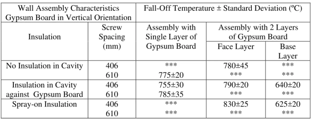
Statistical analysis was carried out to determine the gypsum board fall-off temperature criteria. An average fall-off temperature and standard deviation were determined for each assembly using the accepted thermocouples. The assemblies were grouped as assemblies with no insulation in the cavity, assemblies with insulation (glass and rock) in the cavity and assemblies with insulation sprayed in the cavity. The average fall-off temperature of each group and standard deviation for wall assemblies were also determined and are presented in Table 1.
Table 1: Summary of Temperature Criteria Selected for Wall Assemblies Wall Assembly Characteristics
Gypsum Board in Vertical Orientation
Fall-Off Temperature ± Standard Deviation (ºC)
Insulation Screw Spacing (mm) Assembly with Single Layer of Gypsum Board
Assembly with 2 Layers of Gypsum Board Face Layer Base
Layer No Insulation in Cavity 406 610 *** 775±20 780±45 *** *** *** Insulation in Cavity
against Gypsum Board
406 610 755±30 785±35 790±20 *** 640±20 *** Spray-on Insulation 406 610 *** *** 830±25 *** 625±20 ***
There was little difference between the fall-off temperatures for assemblies with a single layer of gypsum board, with and without insulation in wall cavity, and with different screw spacing. Unfortunately, there was no data for other assemblies. The fall-off temperature for both single and two layers of gypsum board (fire-exposed layer) is more or less similar. However, after the fall-off of the fire-exposed gypsum board
face layer in two layers assemblies, the base layer was thermally shocked when suddenly exposed to the full furnace heat after the face layer had dropped away from the assembly. The thermal shock created cracks in the board and the board did not stay in place as long enough as in the case of the face layer.
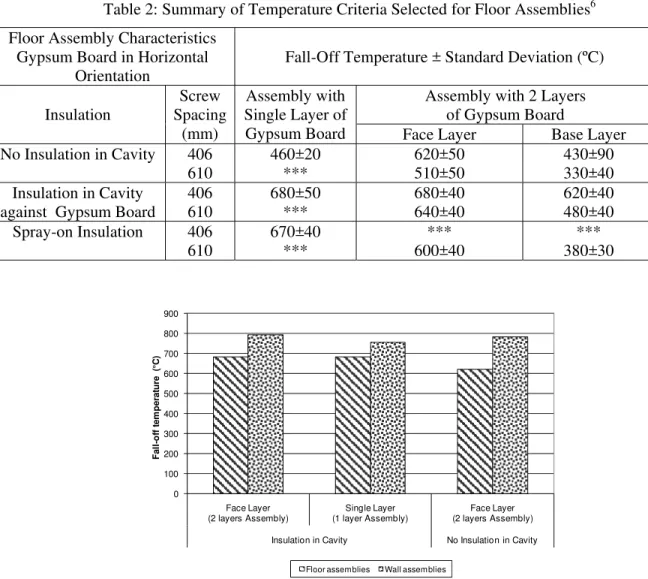
Comparison of Gypsum Board Fall-off Temperature in wall and floor furnaces
The fall-off temperature reported by Sultan6 in Table 2 for floor assemblies was compared to those of the wall assemblies in Table 1 above. The fall-off temperature for wall assemblies, as shown in Figure 3, was approximately 100 ºC larger than those of floor assemblies with insulation in the cavity and 150 ºC larger than those floor assemblies without insulation in the cavity. The higher fall-off temperatures in wall assemblies are explained by the reduced effect of gravity on the gypsum board layers, as most of its weight is supported by the board’s lower edge, which is why it stayed in place longer than those of the floor assemblies.
Table 2: Summary of Temperature Criteria Selected for Floor Assemblies6 Floor Assembly Characteristics
Gypsum Board in Horizontal Orientation
Fall-Off Temperature ± Standard Deviation (ºC)
Insulation Screw Spacing (mm) Assembly with Single Layer of Gypsum Board
Assembly with 2 Layers of Gypsum Board
Face Layer Base Layer No Insulation in Cavity 406 610 460±20 *** 620±50 510±50 430±90 330±40 Insulation in Cavity
against Gypsum Board
406 610 680±50 *** 680±40 640±40 620±40 480±40 Spray-on Insulation 406 610 670±40 *** *** 600±40 *** 380±30 0 100 200 300 400 500 600 Face Layer (2 layers Assembly) Single Layer (1 layer Assembly) Face Layer (2 layers Assembly) Insulation in Cavity No Insulation in Cavity
F a ll -o ff te m p e ra tu re 700 800 900 (° C)
Floor assemblies Wall assemblies
CONCLUSIONS
In this paper, attempts were made to establish temperature failure criteria for Type X gypsum board finishes for wall assemblies exposed to heat in accordance to ULC S101 and ASTM E119 standard time-temperature curve. Also, a comparison was made of the gypsum board fall-off temperature criteria in wall and floor assembly configurations. The following are key findings:
1. Installation of insulation in wall or floor cavities slightly increased the gypsum board fall-off temperature.
2. The gypsum board fall-off temperature for wall assemblies is higher than for floor assemblies due to board gravity effect.
3. Effect of gypsum board attachment screw spacing is less important for wall assemblies than for floor assemblies.
ACKNOWLEDGEMENT
The author wishes to acknowledge Ms. Kristine Campbell, Co-op Student at the University of Waterloo, Ontario, Canada for her help in conducting the statistical analysis.
REFERENCES:
1. Sultan, M.A., Seguin, Y., Leroux, P. “Results of Fire Resistance Tests on Full-Scale Floor Assemblies”, Internal Report No. 764, Institute for Research in Construction, National Research Council of Canada, Ottawa, ON, 1998.
2. Sultan, M.A, Latour, J.C., Leroux, P., Monette, R.C., Seguin, Y.P. and Henrie, J. “Results of Fire Resistance Tests on Full-scale Floor Assemblies – Phase II”, Research Report 184, Institute for Research in Construction, National Research Council Canada, Ottawa, ON, 2005.
3. Sultan, M.A., “Results of Fire Resistance Tests on Full-Scale Gypsum Board Wall Assemblies”, Internal Report No. 833, Institute for Research in Construction, National Research Council of Canada, Ottawa, ON, 2002.
4. Kodur, V.R.; Benichou, N. and Sultan, M.A., “behaviour of Load-Bearing Wood-Stud Shear walls exposed to Fire”, Proceedings of Interflam’2001, 9th International Fire Science & Engineering Conference, Edinburgh, Scotland, 2001.
5. Kodur, V.R. and Sultan, M.A., Factors Governing Fire Resistance of Load-Bearing Steel Stud Walls”, Proceedings of 5th AOSFST International Conference, Newcastle, Australia, 2001.
6. Sultan, M.A. and Roy-Poirier, A., “Gypsum Board Fall-Off Temperature in Floor Assemblies Exposed to Standard Fires”, Proceedings of Interflam2007, the 11th International Fire Science and Engineering Conference, Royal Holloway College University of London, UK, 2007.