MITLibraries
Document Services Room 14-0551 77 Massachusetts Avenue Cambridge, MA 02139 Ph: 617.253.5668 Fax: 617.253.1690 Email: [email protected] http://libraries.mit.edu/docsDISCLAIMER OF QUALITY
Due to the condition of the original material, there are unavoidable
flaws in this reproduction. We have made every effort possible to
provide you with the best copy available. If you are dissatisfied with
this product and find it unusable, please contact Document Services as
soon as possible.
Thank you.
Pages are missing from the original document.
7?
\HS. OF TECHv0
AUG 5 1959
ANALYSIS OF CORRUGATED SHELLS IBRAR
by
SURENDRA TULSIDAS SHAH
S.B., Massachusetts Institute of Technology
(1955)
SUBMITTED IN PARTIAL FULFILLMENT OF
THE REQUIREMENTS FOR THE DEGREE OF DOCTOR OF SCIENCE
at the
MASSACHUSETTS INSTITUTE OF TECHNOLOGY
February 1959
Signature of Author .°.- .. .. . -;
Department
of
Clvil and Sanitary Engineering,
NovETQ ber 24, 1958
Certified by . . . 4-,-0 0- .. . .4
Thesis Supervisor
Accepted by . . . . . .
Chairman ,/bepar tmentl Committee on Graduate Students
2
Abstract
ANALYSIS OF CORRUGATED SHELLS
by
SURENDRA TULSIDAS SHAH
Submitted to the Department of Civil and Sanitary Engineer-ing on November 24, 1958, in partial fulfillment of the requirements for the degree of Doctor of Science in Civil Engine ering.
A few years ago an unusual prefabricated Quonset-type structure known as the "Wonder Building" appeared in the building industry. The structure consists of corrugations
with da -ith of about 8 inches and a pitch of 2 feet run-nin irn mhe longitudinal direction. In addition to these corrugations, there are small secondary corrugations in the transverse direction which are introduced to facili-tate the fabrication of the structure. The longitudinal edges are supported continuously so that each 2 feet wide transverse section behaves effectively as a two-hinged arch.
The secondary corrugations increase the flexibility in the transverse direction, In order to determine the effect of these corrugations, three types of corrugated pipes under axial and transverse forces were investigated. The results obtained were then applied to a structure
havi.~ng idealized major corrugations. The distortion of the major corrugations due to the effect of curvature in the transverse direction, similar to that which occurs in the bending of curved tubeswas also considered. The solution obtained for the ,idalized case was then used to arrive at an approximate solution of the actual structure.
The approximate solution is found to be in satisfac-tory agreement with the available test results.
Thesis Supervisor. Charles E. Norris
Profes,•.: of Structural Engineering Title 4
ACKNOWLEDGEMENT
The author expresses his sincere appreciation to Professor Charles H. Norris, Professor of Structural
Engi-neering, for his invaluable advice, encouragement, and guidance in the development of this thesis. For her
assistance, the author expresses his debt of gratitude to his wife, Pallavi. Grateful acknowledgement is made for
use of the facilities of the M.I.To Computation Center. T~he cot. butions of the following are hereby acknowl-edged: Mr. Kirit Parikh, for assistance in programming for the IBM 704 Computer; Mr. Makarand Desai, Mr. Sukumar Parikh, and Mr. Jayant Shah for assisting in the final preparation; Mrs. Gladys D. Rand for the typing of the thesis; Miss Eva Bonis for preparing the illustrations; and Mrs. Anna Parks for the multilith reproduction.
TABLE OF CONTENTS
No. Page
1 INTRODUCTION - - - - - - - - - - - - -
7
2 SHELLS HAVING THE FORM OF A SURFACE OFREVOLUTION - - - - - 14
2.1 General Case of Unsymmetrical Load - - 14
2.2 Shells of Revolution Under Axially
Symmet-trical Load Distribution - - - - - - - - 21 2.3 Truncated Conical Shell Under Axially
Symmetrical Load - - - 27 2.4 Ring Shell - - - - - - - - - - 33
322 Equations for Forces, Moments, and
Dis-placements in Terms of U and V - - - - 41 3 CORRUGATED PIPES - - - - - - - - - - 43
3.1 Corrugated Pipe Under Axial Load - - - 43
3.2 Explicit Solution for an Axially Loaded
Pipe With V-Shaped Corrugations - - - 56
3.3 Corrugated Pipe Under Pure Bending - - 62
3,4 Corrugated Pipe Under Bending Moment and
Transverse Shear Forces - - - - - - - - - 72
3.5 Verification of Theoretical Results With
Experimental Results - - - - 80
CORRUGATED SHELLS - - - - - 83
L4l
Introduction - - - - - - - - - - - - 834.2 Corru:ted Shell TUnder Axial Tension - - 86 j.>3 o;,rrugated Shell Undr Pure Bending
Moment - - - - - - - - - - - - 90
4.4
Corrugated Shell Under DistributedLoading - --- - - - - - 91
4.5 Shells With Circular Corrugations - 98
5
BENDING OF CURVED SHEI - - - - - - - - - - - 1005.1
Introduction - - - - - - - - - - 1005.2 Pure Bending of Curved. Shell - - - 105
TABLE OF CONTENTS (Continued)
SHELL AS TWO-HINGED ARCH - - - - -- - -
-6.1 Arch Under a General Case of Loading -6.2 Arch Under a Uniformly Distributed Snow
Load - - - - - - - - - - -
-6.3 Unit Stress in the Arch - - - -
-7 THE WONDER BUILDING ARCH - - - - -
-7.1 Introduction - - - - - -
-7.2 Calculation of Stresses and Deflections
-7.3 Effect of the Depth of the Corrugations
on the Stresses - - - - - - - - - -
-7.4 Comparison of Test Results With
Theoret-ical Results - - - - --BIBLIOGRAPHY - - - - - - - - - - - - - - - -APPENDIX - - - - - - - - - - - -APPENDIX B - - - - - - - - - - - - -- - - -BIO GRAP HY - - - - - - - - -Pa1e 121 121 127 130
132
132134
138 141 149159
161 No. 66
LIST OF FIGURES
No.
Page
1.1 Straight Shell - - - - - - - - - - - - - - 8
1.2 Curved Corrugated Shell - - - - - - - - - - - 8
1.3 Corrugated Shell as Two-Hinged Arch - - - - 8
2,1 Stress Acting on an Element of the Shell - - - 15
2.2 Equilibrium of a Portion of Shell Above a Parallel Circle - - - - - - - - - - 23
2.3 Displacements in a Shell - - - - --- - 23
2.4 Truncated Conical Shell - - - -- - - 28
2.5 Ring Shell - - - -- - -
34
I_
~orr3ugated Pipes - - - - - - -44
3.2 Ring Shells - - - 46
3.3 Bending of a Corrugated Pipe - - - - 65
3.4 Shear Forces and Bending Moments on an Element of Pipe - - - -- - - - -= 75
3.5
Corrugated Pipe Tested by Cope and Wert - - - 754.1
Corrugated Shells - - - - - - -- - - - 844.2 Enlarged View of Cross Section of Shell - - - 88
4.3 Simply Supported Shell Under Snow Load - - 92
4.4
Average Area and Moment of Inertia per Unit Length of Corrugation - - - - - - --- - 975.1 Bending of Curved Shell - -- - -- -- - - - 101
5.2 Stresses Acting on an Element of Curved Shell 107 5.3 Distortions of the Cross Sections of a Pipe and a Shell - - - 107
6.1 Analysis of Two-Hinged Arch - - - - - - - - - 122
7.1 Cross Section of Wonder Building Arch - -. - 133
7.2 Transformed Cross Section - - - - - - - - 133
7.3 Deflection and Strain Measurements in Wonder
7
CHAPTER
1
INTRODUCTION
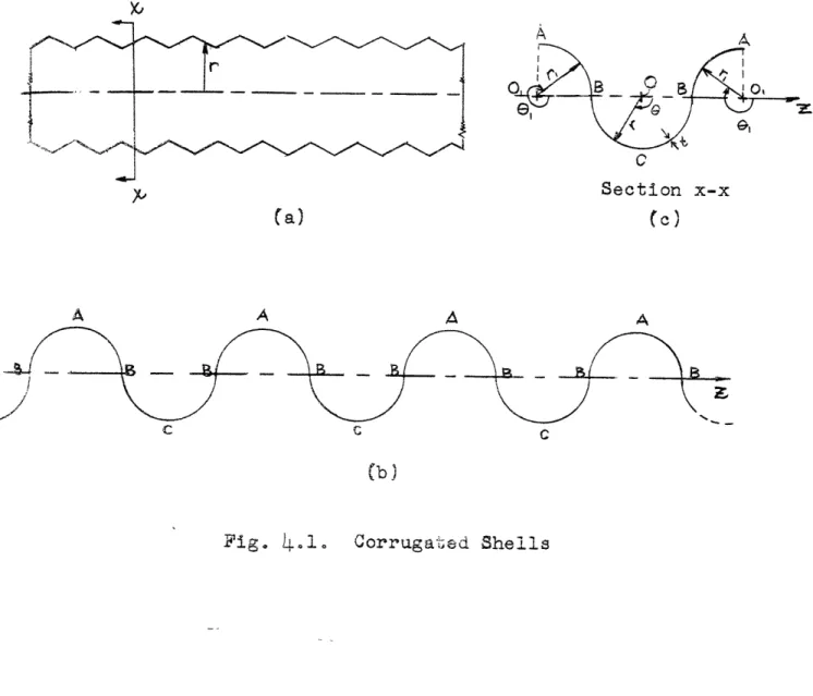
A few years ago an unusual pre-fabricated Quonset-type structure known as the "Wonder Building" appeared in the building industry. The Wonder Building is built en-tirely of 18-gauge galvanized shell metal. The sheet
metal is formed into a bath-tub shape as shown in Fig. 1.1, and then given a secondary curved shape by forming second-ary corrugations into the bottom portion of the shape (Fig. 1.2). The structural component so formed will be referred to as a shell since its behaviour is very similar to that of a long barrel shell.
These shells are then bolted together end-to-end to form a complete arch, which is so supported at its ends that it acts effectively as a two-hinged arch. This arch then forms a two-foot long section of the building, and is completely self-supporting. By bolting together successive arches along the edges A a complete building is formed,
which may be as long as desired ?Fig. 1.3).
The main advantage of this type of structure is the great saving it makes in the cost of labour. Shells with chord length of up to 9 feet are manufactured in the fac-tory. These are then assembled in the field by bolting
them together to form the complete structure, and this pro-cedure requires only unskilled labour. This type of
2.·4
4 A
Section x-x
Fig. 1.1. Straight Shell
4'9
Ci
Section x-x
Fig. 1.2, Curved Corrugated Shell
Ae A
-rk Section x-x
structure is ideal as a roof for warehouses, factories, and industrial buildings.
The presence of the secondary corrugations in the shell increases its flexibility in the span-wise direction. An axial force or a bending moment on it causes bending of these corrugations. This changes the radius of curvature of the cross section, which in turn produces
circumferen-tial stresses, much in the same way as in a corrugated pipe under an axial load or bending moment.
For this reason the case of a corrugated pipe is
rigorously treated. Pipes having the types of corrugations shown in Fig. 3.1 are considered. It is seen that the cor-rugated pipes shown in this figure can be formed by
combin-ing several shells of revolution, either conical or rcombin-ing shells. The general solutions for these types of shells are given in Chapter 2. By using appropriate boundary zonditioins, the stresses and flexibility of a corrugated pipe can be obtained as showr in Chapter 3. The increased flexibility of a *orrugated pipe can be taken into account by using a "reduced nodulus of elasticity," so that the deflections of corrugated pipes can be calculated by
con-sidering the pipe to be plain and using this reduced modu-lus as its modulus of elast *ty.
The solution obtained for the pipe is next applied to a shell with a straight axi, of an idealized cross sec-tion shown in Fig. 4,1(b), and having secondary corrugations
10
of the types considered for pipes. This procedure is
strictly valid only when the shell is under pure bending so that the longitudinal forces are linearly distributed over any cross section. However, under the influence of snow and dead loads, transverse moments occur which distort the cross section, as in a multiple barrel shell, so that the assumption of linear distribution of the longitudinal forces is not strictly correct. But since the shell is stiffened transversely by the secondary corrugations and since the shell is long in comparison with the cross-sectional dimensions, the effect of the distortion of the cross section is very small on the longitudinal behaviour as explained in Chapter 4. Therefore, the longitudinal forces can be assumed to be linearly distributed and the solution for corrugated pipes can be used for these shells.
When these shells are curved and are subjected to a bending moment, distortion of the cross sections occurs similar to that which takes place in thin curved tubes. Not only does this distortion of the cross sections
in-crease the flexibility of the shell but it also makes the distribution of the longitudinal forces nonlinear. It is shown in Chapter 5 that the secondary corrugations help to stiffen the transverse sectiola, thereby considerably reduc-ing the distortion of the cross -.ctions. In nearly all cases the distortion is so small that it can safely be
11
neglected, and the longitudinal forces can be assumed to be linearly distributed over any cross section.
After this the analysis of the shell as a
two-hinged arch can be performed very simply. In Chapter 6 the method of superposition is used to obtain the external
moments and thrusts on any cross section. By neglecting the effect of distortion of the cross sections due to the curvature of the arch and the effect of shearing deforma-tions, the analysis reduces to that for an ordinary arch. Having obtained the external moments and thrusts, the unit stresses can easily be found by using the solutions devel-oped for corrugated pipes. The deflections can easily be obtainqd by considering the shell to be plain and using the reduced modulus as its modulus of elasticity, as in the case of corrugated pipes.
The cross section of the actual Wonder Building arch (Fig. 1.3) is much different than the idealized cross section of Fig. 4.1(b). The shape of the actual cross
section is such that it cannot be represented by any simple geometrical figure. The problem is further complicated due to the fact that the shell has secondary corrugations in the bottom portion only. The corrugated portion consists of a circular arc and two tzai.ents as shown in Fig. 7.1.
An approximate solution *fr this shell is given in Chapter 7. It is assumed that the circular corrugated arc
is a part of a complete pipe of radius 9d125 in., and that each of the two tangents is a part of a pipe whose radius is equal to infinity. The reduced moduli of elasticity for these portions are then equal to those for the corre-sponding pipes; the modulus for the portion which has no
secondary corrugations is simply the modulus of elasticity of the material. The stresses and deflections are then found by a method very similar to the method of trans-formed sections used for beams of composite sections. The
theoretical results were found to be in very good agree-ment with the available test results.
It is shown in Chapter 7 that for a given moment on any section of the shell, the maximum stress at this sec-tion depends primarily on the depth of the secondary corru-gations; it increases as the depth increases. The shells are corrugated in the transverse direction mainly because it makes it easy to bend the shells into circular arcs. Therefore, the depth of the secondary corrugations in-creases with an increase in the curvature of the arc. But as the curvature in.reases, the span of the complete arch becomes shorter, so that the maximum imomeant in the arch due to a given loading decreases. Thus, an increase in depth of the secondary corrx.uions is accompanied by a reduction in the maximum moment in the arch, or vice versa, which enables one to use the same cross section over a wide range of span length.
13
Throughout the analysis it is assumed that the material follows Hooke's Law, is homogeneous, and iso-tropic.
14
CHAPTER 2SHELLS HAVING THE FORM OF A SURFACE OF REVOLUTION
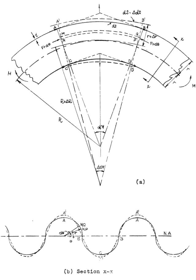
2.1. General Case of Unsymmetrical Load. Fig. 2.1 shows an element, ABCD, cut from a shell of revolution by two adjacent meridian planes and two parallel circles. The position of the meridian plane is defined by the angle e,
measured from some datum meridian plane, and the position of the parallel circle is defined by the angle 0, made by the normal to the surface and the axis of rotation. The meridian plane and the plane perpendicular to it are planes
of principal curvature at a point on the surface of revolu-tion, and the corresponding radii of curvature are denoted by r1 and r2, respectively. The radius of the parallel
cir-cle is denoted by r o . Thus the length of the sides AD and
and BC is rd~ that of AB is r de, and that of CD is dr o
(r0 + o do) de
The forces and moments per unit length acting on the element ABCD are shown in Fig. 2.1 and are positive when acting in the directions shown. In obtaining the equilib-rium equations, it will be assumed that the shell surface is free of any external load.
Equilibrium Equations: Let " consider the equilibrium of the element ABCD by first projecting the forces in the di-rection of the tangent to the meridian. The normal force acting on the side AB is
15 0 Cfl 4a P1( a 4ŽO C, Co0 ocl Cr 0 4-Ž r/r oJ *1-K~
S16
Norode
The corresponding force on CD is
(@
+
do)(r0
+ 2 do) de
By neglecting a small quantity of the second order, the resultant of these two forces in the y-direction is found
to be equal to
N - dd + r de= (Nro) dde (a)
The radial shear force,
Qrod
d, on the side AB has no ponent in the y-direction, while on the side CD the com-ponent of the radial shear force in the y-direction is- (q4 + -do)(r 0+ d ) ded# and this is equal to
- Q# rodde (b)
if only the quantity of the first order is retained.
Now let us consider the forces acting on the other two sides, AD• and BC. The normal forces on these two sides are Nerldý and (N- + de) rd , and have a re-sultant in the direction of the radius of the parallel circle equal to Nerido de, The component of this force in the y-direction is then
-
Ncrcosodode
(c)
Finally, the lateral shear force on AD is Ne~rldo and on BC is
(N9 + -ade) rd
which give a resultant in the y-direction of
L rldde
(d)
Summing up the forces (a) to (d), the equation of equilib-rium of forces in the y-direction becomes
- (Nr o) - NBrcosp + a- rm- ro = 0
The other five equations of equilibrium could be obtained similarly, and they are stated below, together with the one obtained above:
SF =0 F=0 T M
=0
x:
(N
r )-
Ner•cos#
+
-
r
-Q~
=0
SNe
: (N ero)+ r+ +N rcosoQrisino=0 SNro 0+ Nergsiný + (Qr O ) + - 0~k
(
r
)
-Mr oos -
r --
o
r
=
0
ýMmy
=0
o .
•
M, D
cos ~-Q-9rr = O
M7 = 0 : M1 ero Mr r sin - Nrr + N rorj = 0
(2.1)
It can be shown that
(e)
Npy = Nse]
Nfi& N(9
M MJ
if the thickness t of the shell is small in comparison with the radii of curvatures, r. and r..1 However, an
S Timoshenko, "Theory of Plates and Shells," pp.35.2,353,
i"
consistency results when these relationships are substi-ted in the last of the equilibrium Eqs. (2.1). This consistency is due to the fact that expressions (e) are only approximately true. If the exact expressions for Ne4 , N e, Me4 , and M#e are used, then the last of Eqs.
(2.1) is identically satisfied. In our further discussion, it will be assumed that the last of Eqs. (2.1) is always satisfied, and that the thickness of the shell is small in comparison with the radii of curvature, so that expressions (e) are valid.
Stress-Strain Relationships: With eight unknowns and only five equations provided by statics, additional equations, based upon the stress-strain relationships, must be intro-duced. If ( denotes the unit strain in the meridional direction, E~ the corresponding strain in the direction perpendicular to the meridian, E4e the shearing strain,
iYsand)e the changes of curvature of the meridian and the
plane perpendicular to the meridian, ~e the change of twist, E the Modulus of Elasticity and ) the Poisson's ratio, then, for thickness, t, small in comparison with r2
and rI, we have2
e- : · P: i
N Et
N
Et
6
N = (e4+9 e) i N 1 - )M-Et=
)
(ý+( -EtM(f)
12(1.9
' )Y
el
e 12(1-V2)
Et M EtNe=e
=
: -
:1
12(2y)
Ye;
)J
7,-f^
If
P I 4 4 ~· o a -3 i: 4 ol I~ ~ 4 cj
~P
7 E = 1) - ;e=
r,
1
(
ae
Csc"+V
ota-w)
cn#w -1 bu + 14v ctnr
r.
r
2-etn
.1 a-+r
•rcs
,
c+ csc (csc_ + _) rFae
rF FerI
•1 o4s
U
1+
F,"
ra be r. F. r (g)3 A. E. H. Love, "A Treatise on the Mathematical Theory of Elasticity," pp. 521,524.
Strain Displacement Relationships: The strains and the changes of curvature and twist can be related to the dis-placements n, v, and w, where u and v are the displacements
in the directions of the tangents to the parallel circle and meridian, respectively, and considered plus when in the direction of increasing ) and 0 , respectively; and w is
the displacement in the direction normal to the shell sur-face, plus when directed inward. These relationships are
.--- \
19
r
G Z
20
Stress Displacement Equations: Substituting the strain displacement equations (g) into the stress-strain
relation-shios (f) gives Et 1 v 9 u ctn w
Et 1l
1
u
S rx "r r , (2.2) s 1 1 uwa
°
tn
+(v + ) seco ( r csc + -- ) ctn r r~ r r e 1 1 where D (2o3) 12(--NV2 )Substituting expressions (2.2) in Eqs. (2.1) will then, yield five equations in terms of the five unknown quantities u, v, w, Q , and Qz,
MM(N ro)- Nericos - Q r = 0
N r
O + N rsin + - (Qoro) = 0d (Mor
o)
-
Mercoso
-
Qpror, = 0
and the stress displacement Eqs. (2.2) become
Et dv y
Np
=-
--- t
2 -- w) + -(v
ctn
- w)
Et Y V dv _I M -= - 1 v + 1I dw d 1w v dwtnr r r do
1 11
-
2 1 1J. 717 1 Uý(2.4)
(2.5)
I
Substitution of expressions (2.5) into the equilib-rium Eqs. (2.4) yields three equations with the three
2.2. Shells of Revolution Under Axially Symmetrical Load Distribution. It can be concluded from the condition of
symmetry that only normal stresses will act on the sides of the element ABCD (see Fig. 2.1) lying in the meridian plane. Hence
QgN= N = Ne = Me = Moe = 0
Also due to symmetry the circumferential displacement u must be zero. The remaining stresses and displacements will all be independent ofG. With these conditions the equilibrium Eqs. (2.1) reduce to
h
L
P
I:
22
unknowns v3 w, and QQ. But considerable simplification of the equations can be obtained by the introduction of two new variables, U and V, where
2 +
(2.6)
v = l Cv +
ýa-
)
r
dO
It should be noted V is the expression for the rotation of the tangent to the meridian.
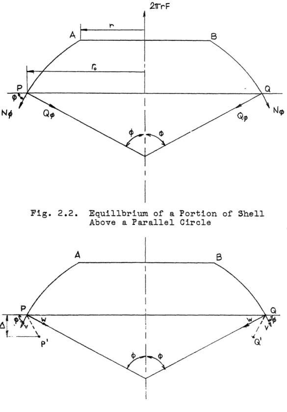
To simplify the transformation, we replace the first of the equilibrium Eqs. (2.4) by one obtained by consider-ing the equilibrium of the portion of the shell above the parallel circle defined by the angle ý (Fig. 2.2). If the resultant edge load on the edge AB of a shell of revolution is 2vrF, then the equation of equilibrium is
27r
N
sinl
+
2fr
Qocos
=O
2irF
from which
N~J csc 1 - Qectn F csc• U ctn) (2.7)
From the sec.nd of Eqs. (2.5) we have
This method of analysing stresses in shells was developed for the case of a spherical shell by ,. Reissner, "Muller-Breslau-Festschrift, p, 181, Leipzig, 1912 it was
gen-eralized aid applied to particular cases by E. Mpissner, David W. Taylor Model Basin Translation 238, and by H.
Wissler, "Festigkeitsberechnung von Ringflachenschalen, doctoral thesis, Zurich, 1916.
23
2¶rrF
g
i
Fig. 2.2. Equillbrium of a Portion of Shell Above a Parallel Circle
Fig. 2.3. Displacements in a Shell
r
B
s ·g ··~; .. 7 I' ,i ·· · :5 t· r. .. e ·I` ;r'Ner sin
= -
N
-ro-
r
o)Substitution of Eq. (a) in this and noting that r
-r2 sino gives
N - (rF csc + ) (2.8)
From the first two of Eqs. (2.5) we readily obtain
- w = r (No -Y N
dv r
C
(a)
v ctno - w = ( - 3N)
Elimination of w from these two equations leads to
- v
ctn
=
1
L
r
+rs)
N (Cr,+ Ir) N
(b)
Differentiation of Eq. (a) gives (if t is assumed to be constant)
dv ctn -v cscj- -dw d= r(N,-N)
dv
The derivate - can now be eliminated from the last two
djs
equations, to yield
v
+ d = r
d
V
=
o
(r
+Yr
)
NO -(r ++Vr
)
N]
1 d (Ne N,
Substituting' expressions (a) and (b) for Np and Ne, we finally obtain the first of the two equations relating to
V
a
d2U
1 [
r
r
2o
dU
1 r
r
, I- + d~ )+ ctn tn UCUr
dido
1 ado
rI
r =Et V +Z1
rF
tan
1 rd
r
where Z = - rF csc0 tnra
+)rE
1ri
do rJ
cc)
(2.9)
The second equation relating U and V is obtained by sub= stituting the last two of Eqs. (2.5) in the last of Eqs. (2.4) and using the notations (2.6). In this way
rr da[ r 2 r dV 1 r'"
rd
+ 1
(-
+---
ct
n
r r
t1
-ycU
r
d$a
rr
rL r
2U
By introducing the notation
.d2 + (2)+ ctn d-( )
r
dao
r.[7
r rd1 ctna
(C...)
(2.
Eqs. (c) and (d) can be written in the following forms:
L () + ÷- = EtV + Z r
L (V)
"V_
"r
u
(da)
10)
(2.11)
This system of two simultaneous differential equa-tions of the second order can be reduced to a single equa-tion of the fourth order. Operating on the first of Eqs. (2.11) by L(...) gives
LL(U) + 9L(U-) = Et L(V) + L(Z)
Substituting the second of Eqs. (2.11) in this gives
L(V) = V U
•
(U) +
~-
Z
U
r 1 D Etra L r j D
Using this, we obtain
LL(U) + L( U
r
rI
L (U)
U
Et U + L(Z) -
z
r2
D
ri
If r, is constant, as is the case for spherical, conical, and ring shells, then
L(U) = li
n(U)
r r2
Using the notation
=
- 2(2.12)
LL(U) + M(U) = L(Z) -
(2.13)
Similarly
LL(• )
+t(V)
= -
(2.14)The .pplication of Eqs, (2.13) and (2.14) to partic-ular cases of a truncated conical shell and a ring shell will be discussed in the next two articles. However, the expression for the relative displacement between two
parallel circles will first ',- found.
The deflection p of any point P on the shell sur-face in the direction of the shell axis can be found in
27
terms of the stresses Ný and Ne. In Fig. 2.3 P' represents the displaced position of P.. From the figure, it is seen that Ap is given in terms of the displacements v and w by the expression
y = v sin•+ w cos$
Integration of the differential eq. (b) gives
V [Na N(r, + yr.) - N,(r + yr) do + C} (e)
in which C is a constant of integration. From Eq. (a)
r
w = v ctn - E (Ne
-NON)
(f)
Substitution of these two expressions for v and w in the
expression for
Ap
yieldsAp J(r,,+yr,) Ne(r,+yr ra 1 d -rr,(N-N9 ) +
c
The relative deflection between two parallel circles whose positions are defined by the angles
4,.
and po can be found by solving the above expression for A between thelimits 4. 1.zd a~ Denoting this deflection by
A,
we haveN=
+r
{
[r+ry+rr)-
NN(r+
r1]
-
)
(2.15)
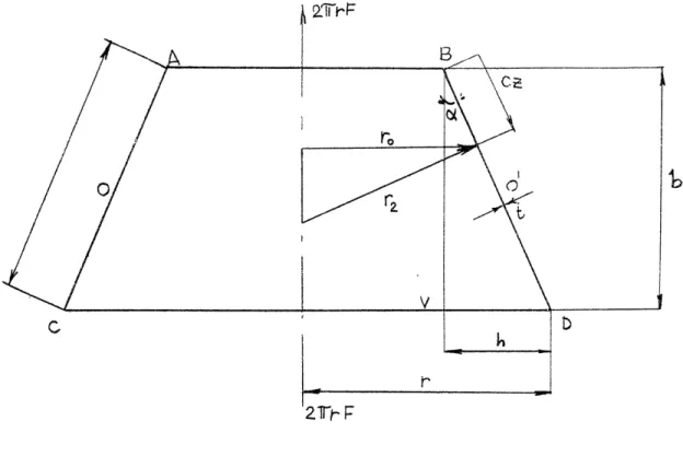
2.3. Truncated Conical Shell Under Axially Symmet.zical
Load. A truncated conical shell, ABCD, is shown in Fig. 2.4. The dimensions b, c, h, and r are defined in this figure.
28
Fig. 2.4. Truncated Conical Shell
r
· 1
`~-·
I
4
4 Ac 4 r ( h h dr -_2 ha
cos-c
r
r z
dz
coso-Substituting these expressions into (a) and putting r = oq the symbol L(...) becomes
L...)
=
a
htan+
-c2 dz' ca cosoC dz r
For the special case of a conical shell, Eqs. (2.9) and (2.13) reduce to
(b)
(c)
To apply the general equations developed above to this case, we introduce in place of 0 a new variable z which is the product of c and the distance along the meridian from the edge AB (see Fig. 2.4). The length of an infinitesimal element of a meridian is now cdz, instead of r do. As a
result,
d
d=
1
sd
d
- =d r
(d
d
) =t da
+1 dr2 d
2 " dz dd z C do dz
Using these transformations, and noting that r. is constant for a conical shell, the operator L(...) of Eq. (2.10) becomes rrPd2 1 drP r L(...) = "- () ... + ( + ctn ) - d.
ca
dz c dz r r c dz 1ctna
(..')
(a)
r(a
Observing that 0 is constant, and using the notation
wiffor . B/2 - , we obtain (see Fig. 2.4)
- -
-1
29 ·i ti r ca
s
i
30
Z = -r r F seck tancx (d)
2
and LL(T) + 4'U = L(Z) (e)
The expression for Z when operated by L gives
L(Z) = 0
Eq. (e) then becomes
LL(U) + U4 U - 0 (2.16)
which can be written in one of the following two forms:
L
[L
(U)
i,
i
U
i2U
L(U)
:
ifrUJ
0
where i = V;""
These equations indicate that the solutions of the second order equations
L(U) + i LU
I /=
0
(2.17)
are also the solutions of Eq. (2.16).
Using the expressions (b) and (c) in the first of Eqs. (2.17) gives
(1 h h )
ca cos r r 4d ac cos dz
tan
'%
cos•
.
i
U - 0
r (l-b/r+h/r z)
r
(f)
a s
a
cosoL
be
r rt
finally yields the equation
2 d 2U dU
(1
-
e + ez) dz--
+
C(1
-
+
z) dz
- 2- ia (1- + z)] U2 = 0 (2.18)
The solution of Eq. (h) can be found in the form of power series in z multiplied by a power of z,
0o
U =
1
s
A
k
s)
k=O
The method of Frobenius was used for the determination of s and the recurrence formulae for the coefficients.5 It was found that s = 0 and 1.
For S = 0, the recurrence formula is
k(k-l)(1-F)
A
k=-
(l-C)(k-l)(2k-3)
Ak-l
+ L)(k-)(k-3) + ia(l-e' Ak- 2 + iaP Ak-3 k 1
When k 1 , the recurence formula is identically
satis-fied, leaving Al as well as Ao arbitrary.,
When s = 1, the solution obtained is the sate- as
that corresponding to the coefficient A. for the case F. B•, Hildebrand, "Advanced Calculus for Engineers,"
s = 0. Hence the complete solution of (2.18) can be ex-pressed as
U•r
1
=
A
k
zk
k=0 where A = - 1P 2 {(l-k)(k-I)(2k-3) Akl I k(k-1) (1e)k+[ a(k-l)(k-3)+ ia(l- )j
Ak-2 + ia? Ak3
k
a2
(1)
Separating the series (i) into its real and imaginary parts, we obtain
U1 = A (I, + i I2) + A az(I3 + i I,)
where I,, ... , I, are power series which are convergent when (I-?+ ( z)
#
0.By inspection, the solution of the second of Eqs. (e) is U2. = Ao( 1, - i 12) + A, z(I- i 14)
Solutions Ua and U1 together represent the complete system of independent solutions of Eq. (2.16). By using the sums and differences of solutions U1 and U., the general solu-tion of Eq. (2.16) can be written in the form:
U = A +IB1 +
BI,
+ Cla + DI(2.19)
where A, B, C, and D are arbitrary constants.
Substituting (2.19) in the first of Eqs. (2.11) gives
4
33
= in •, n
V [(l-ee(-a z)(Al,+BI +CIt+DI4) Etb(l-9+ez)
+ (1-+ez) (AI'+ BI + CIa+ DI)
-
!(AI,+ BI,+
CI+ DI4)
+ Ph seco csco (2.20)
9 dI 1 d21
where I d , I dI
dz2
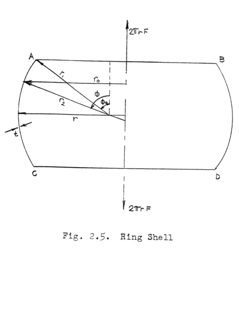
2.4. Ring Shell. A ring shell is shown in Fig. 2.5. The radius r is as defined in Fig. 2.5. The angle Q varies from o to 7T- o . For this case it is convenient to solve
Eq. (2.14) for V. Since this is a linear nonhomogeneous differential equation, its solution can be separated into VH, the solution of (2.14) with Z = 0 (homogeneous solu-tion), and Vp a particular solution of Eq. (2.14).
Homogeneous Solution: Setting Z = 0 in Eq. (2.14) gives
LL(VH) + y? VH = 0 (a)
Eq. (a) is similar to Eq. (2.16) and hence it can be con-cluded that the solution of the second order equations
L(V) + ± VH = 0 (b)
are also solutions of Eq. (a) From Fig. 2.5 we see that
r= constant
rz = (r-rj) csc + r 1 (c)
dr
G D
S21-r :
Fig. 2.5. Ring Shell
With these relationships, the symbol L(...) of Eq. (2.10) becomes r 2
d(
2dOs
.°) + ctctL d . 1 r ctn 2aUsing this in the first of Eqs. (b) gives r d2V H 1 1 2 d2 I dV + ctn dVll
r
1do
- ctn2• V 12
A further simplification is obtained by introducing the new variable
x
=
1 - sinr. With this changed d- = -d
cosý
dad
~Using these relationships,
d dx2 Eq. Ce) sin d
-(f)
(g) becomes d 2V + dxar
r (-- a sin r rcos_
2dVH1
sin dx - ( ctn2 By noting that cosO = 1 - sin2o = x(2-x) ctn os x(2-x) sn tna(l-xsin'O5
(1-x),
r-rS x a)CsC4+ r, = .-. 1-x 35(d)
+ /~ = 0 (e) r r2 I 2itiý and r 2 = (r-r si
t: ·'
x(r-rax) (2-x)
.... (2-x) r (1-x) dHi + 1 r-r.x x(2-x) dVH1 dx r r, 1-x dxI
x(2-x)
1 iv
=0
(l-x)(r-r
x)
H
1
rl(1-x)(r-rax)
Multiplying by , and introducing
xr the
nota-tions
ra
r
r
12(1-~)
r
2 S r r t(h)
finally yields the equation
(2-x)+(-l-x)
2
d
(+-x1(-)x)a
-
Ax(2-x) (1-A.x)
dV
dxz x
Saxa (2-x) - i a x(1-x)(l-Ax)
x -
IVH
= 0Here again the solution can be found in the form of power series in I multiplied by a power of x
VH1
=
xS Ak xkk=O
The method of Frobenius was again used for the determina-tion of s and the reaurrence formulae for the coefficients. It was found that s = 0 and 1/2 for this case. For s = 1/2
the recurrence formula is we have
(i)
· 4L
11136
7-J
37
Ak k(2k+l 4 (j2k-1)(l+4) - ia
Ak--
fe(k-1X2k-3)(1+X) - 2a - in(l+wX)
Ab-2
,+
Jj
(2k-3)(2k-S)
- -iaX
kS1
>)
A second solution corresponding to s = 0 is of the form
V =
Ak
xk
Ill
k=O
Because of symmetry,
[V=
-VjT for all values of4. Since the series corresponding to s = 0 cannotsatisfy this condition, the second solution should not be considered. Hence the complete solution of Eq. (i) can be expressed as
VH X1/2 Ak (k)
k=0
where Ak is given by the recurrence formula (j).
Separating the series (k) into real and imaginary parts, we obtain
V1 = Ao(J, + i
J
2)
(1)
where J. and Ja are power series multiplied by 1/2, the series being convergent when (2-x)(C1-x)2 ý 0.
As was shown for the case of the truncated cone, the complete solution of Eq. (a) can be represented in the
following form
VH = C JI + CaJ2
where C1 and Ca are arbitrary constants.
Substituting (1) in the first of Eqs. (b) gives
L(J, + i J) + i (J + i Ja) = 0
*. [a 1 JJi[Jp) + )(
+s
Jj =O
For this to be an identity,
L(J3)
=/ J2L(J2) = -a2 J,
Substituting Eq. (m) in the second of Eq. (2.11) and using the above relationships gives
U = D (C2a H + C3) rI 2 J - (C,2 - C J2
Having obtained the homogeneous solution of Eq. (2.11), we shall next attempt to find its particular solution bystem.
Particular Solution: If
S = SI + i S
is a particular solution of the inhomogeneous equation
L(s)
-
i/L
2
S = Z
then it can be shown by direct substitution that
VP = -s P 1 S Co)
(p)
(q)
(m)
(n)
ii I pis the particular solution system of Eqs. (2o11). The solution of the differential equation (p) will also be obtained in terms of power series~
Using the relationships (c), (f), and the first of the expressions (h) in Eq. (2.9) gives
z = F(1X) cos5 2 +(2 - 3Xx)
X2(1-\x)(1-x)'
Let S = SI+ i S2 = Fr(l-A) W ctnci (r)
The differential equation (p) then becomes
L(W
ctn4)
- i
W
W ctn =
cos
(2+~- 3x)
Xr,(1->x)(1-x)X
The symbol L(...) is defined by (d), and 0 is related to x by the expression (f). Using this in the above
differ-ential equation gives
(1- x)(2-x) e1-x)
w
dx'+
(1-XX)(1-x)
x
(1-+x)(lx)2+2(l x)-xx(l-x)(2-x)
dx
S 2x(e-l~x
-•x(l-x) (1-x)-x(1-x)
2(2-x)-
ax(l-ýx)(l-x)'
w
- (2+X) xW-3x~ (s)1
x
A solution of the above equation can be taken in the form
oc
=
=Bk
xk(t)
i
Bk k = + (k-s-l)Ps+-
sI
[k-s-l)(k-s-2)Rs+
l s=O1+
Qs+J
B
k-s-(Bo= 0 , k1l) 0
(u)
whereN = C2+%1)
; N = - 3% ; Na = N = N = ... = 0
R = - (5+L4)
; R2 = (4+10k+
2X
2
)
Ra = -
(1+8X+
5X
2)
R= = 2(1+2X) ; =-P = - (5+8X) ; P6 = (3+15A+ 5A!) ; P? = - (1+lOA+ l0>• ) ;
P? = h(3+7T-) ; P
=-
2Q = (2-ý- is ) ; = - (3X+ 2 - 3 ia- ialX);
Q
;3 ~-i, 3 ia,)J;Q$Separating the series into real and imaginary parts, we obtain
W= J + J
where J. and J4 are converging power series when
(1-x)(2x-x)(-x)
ý
0.
L
40
Substituting the series (t) in Eq, (s) and equating the coefficients for each power of x to zero, we obtain the following recurrence formula for Bk
S, and S. can then be related to J3 and J4 by the expres-sion (r) giving
SI
=
Fr(1-ý)
ctn# Ja = F r(l-X) V x JS
=
Fr (l-h)ctn J4 = F r(l-X)v
(
J,,Substitution of these relationships in (q) yields
=
Fr(l-)
/x2-x)
VP
# -D
1-X
Up
=
Fr(1-)
x(2-x
1-x (Ja -- J4
)
as the particular solution system of the differential equations(2.11). Since these are linear equations, it is permissible to add the homogeneous and the particular
solu-tions to obtain the complete solution.
Thus U
= U
H
+ Up
V = VH + V or O r~ U = D Ct + C0 - .c cc i - C + Fr(l-x) x2-x) 1-x ( J ) *(2.21) (2.21) V = C J + CJ a Fr(l- l x2
4 JX 'j 4_ (2.22)2.5. Equations for Forces, Moments, and Displacements in Terms of U and V. Having the expressions for U and V, we ~Jlm'
S42
can obtain all the forces, moments, and displacements in terms of these two quantities. The forces No and Ne are
found from Eqs. (2.7) and (2.8). The bending moments MO and Me are obtained from the last two of Eqso (2o5) by set-ting 1 (v + d equal to V. The only displacement that will be of interest is the relative deflection between two parallel circles defined by the angles
(j
and (,. This is obtained by substituting Eqs. (2.7) and (2.8) into Eq.(2.15). The equations resulting from these substitutions are 1 ("P
r
2 N- (Fr U- ctnq) N9I(r
F csc2ý+dI dV
V
ctn
= - D ( + ) r dr r 2 (2.23) r d r - (- ) tn d+ ( + F sc +- d - )U ctn r. doLi
~l
I
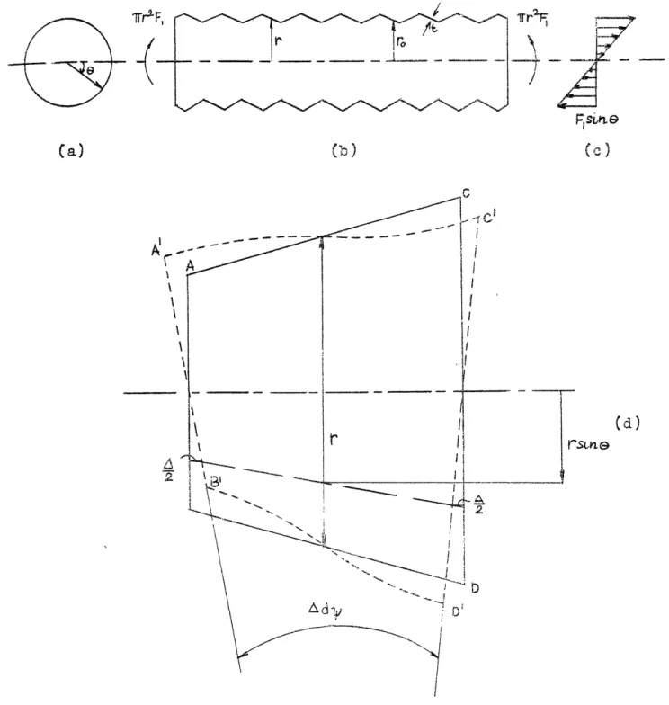
3.1. Corrugated Pipe Under Axial Load. Pipes with three different types of corrugation are shown in Fig. 3.1, each
subjected to an axial load of 27-F. The first one has V-shaped corrugations; the corrugations -of the second one
consists of concave circular arcs, while those of the pipe in (c) consist of a series of alternating concave and con-vex circular arcs. These three types of corrugations will be referred to as V-shaped corrugations, cusped corruga-tions, and undulating corrugacorruga-tions, respectively.
The dimensions of the corrugation will be defined by the symbols b, c, and h. (See Fig. 3.1.) In our
fur-ther discussion we shall refer to b as the width of a corrugation, c as the length, and h as the depth of a corrugation. The thickness t of the pipe wall will be assumed to be constant over the entire pipe length. The radius r of the pipe will be considered to mean the aver-age radius of the pipe. It wi22 be seen that all the quantities defined above have the same meaning for all three types of corrugations.
Each of the three corrugated pipes shown in Fig. 3.1 can be considered as being formed by combining several
shells of revolution such as ABOC, CDEF, .... . If the
pipe is sufficiently long, any one such shell can be ana-lysed and considered to be typical for the entire pipe.
CHAPTER 3
O
o
4.3 O bO /0: a~ ar LL Kl ," < , "- NJ/ '\ f V 1-'I Crl w od-4
'Q ) o 0 660rl 0 f O eU 0 O ori - -I-]- -- - ---_ j---C (4 a LL 0 Lii a3 ^ u--- +---r---
- - - L-L u. ... 1 --TCFi
pP~ ~tC-~I~CC---~! ~Z--~I. uCI ~C4
i
~raeL. I I
I
r,I
/ a ri
II
45,
The shells ABCD, CDEF, .... for the pipe in (a) are
truncated conical shells, whereas those for (b) and (c)
Aare ring shells. Each one of these shells is subject to an axially symmetrical load of 2wrF. This load acts along the edges AB, CD, EF, .... only, so that the shell surface can be considered to be free of any external load (the weight of the shell being neglected).
In Chapter 2, we have obtained solutions for trun-cated conical shells and convex ring shells, such as ABCD of Fig. 3.1(a) and (c), respectively, subjected to the
type of loading mentioned above. The solution for the con-cave ring shell, such as CDEF of Fig. 3.1(b) and (c), can
be directly obtained from that for a convex ring shell, if
the parameter
(2.1)
r
is small and if the edge conditions are the same. For if
is small, the radius of curvature r, is approximately the same for corresponding points of the two shells (see Fig. 3.2)., However, the curvature of the meridian for the con-vex and concave shells is of the opposite kind. Hence,
the force No and moments M, and Me for the two shells
which arise due to this curvature will be of the same mag-nitude, but opposite in sign, for these two shells,
where-as the force Ni will be of the same sign and magnitude. Also since the forces and moments are of the same magnitude
csc r-rcsc pl4 ,
(sLrL- sLa 4 )1
C(I
- $tx~4
(a) Convex Ring Shell
r c - r, (str_ -S g&)jo e rcsc
(bj Concave Ring Shell
Fig. 3.2. Ring Shells
1
tion of their axes of revolution must also be the same. Thus, if is small the solution of a convex ring shell
can be directly used for a concave shell by only changing the signs of Ng, MN, and Me. Unless otherwise stated,
will be assumed to be small in our further discussion.
In each of the three cases, it is only necessary to analyse the shell ABCD and consider it to be typical for the entire pipe length. The stresses and deflection for the conical shell can be obtained by using the general so-lutions (2.19) and (2.20), while those for the ring shell can be obtained from (2.21) and (2.22). The constants ap-pearing in these solutions can be determined from the boundary conditions at the edges AB and CD.
Because of the restraint from adjacent shells, the rotation of the meridian at t•he edges AB and CD of Fig.
3.1(a) and (b) must be zero, Fu-rthermore, there can be no component of force normal to the axis of revolution at these edges. The expression for the rotation of a tangent to the meridian is given by the second of Eqs. (2.6), while the component of force normal to the axis of revolution is equal to Q~sin~ - Nocos (see Fig, 2.2). The forces Q0 and NT are related to the parameter U by the first two of Eqs.
L47
for the convex and concave ring shells, the strain energy due to the axial force of 2wrF must be the same for the two. By equating the strain energy to the external work, it follows that the expansion of the shells in the
direc-ii i,
48
(2.23). Thus, the boundary conditions at the edges AB and
CD can be written as
v = 0
sYino - = c(U Icos s - Frctn4) = 0a)
For the pipe with the undulating corrugations it can be concluded from the antisymmetry of the deformations that there would be inflection points at the edges AB and
CD and that the circumferential force N8 , given by the third of Eqs. (2.23), must be zero. In equation form the boundary conditions at the edges AB and CD are
1 dV
(b)
Ne - (rFcsc 6 + d)' =0
where V is the rotation of a tangent to the meridian.
With these boundary conditions the constants appear-ing in the solutions (2.19) through (2.22) can be deter-mined, thereby obtaining exipressions for U and V for all
the three cases. Substitution of these expressions into Eqs. (2.23) will finally give the forces and moments in the
shell and the relative deflection A between the edges AB and CD can be found. It should be noted that A represents the deflection of an axially loaded corrugated pipe of length equal to the perpendicular distance between AB and
CD. The unit stresses in the circumferential direction and in the meridian direction (i.e. perpendicular to the
49
circumferential direction) can easily be obtained from the values of the forces and moments.
In the meridional direction, the unit stress in the extreme fibre is given by
N
6MO
In order to obtain a dimensionless quantity, we shall divide 6-0 by
-
=
(d)
t
which is the stress in a plain pipe having the same thick-ness and mean radius as the corrugated one. The ratio
6/6- will be called the meridional stress factor and will
be denoted by the symbol Ký
No 6MS
Similarly, for the circumferential direction we have Ne 96Me
in which Ke is the circumferential stress factor.
For all practical purposes it is only necessary to know the absolute maximum value of the stresses. So in our further discussion we will take Ke and Kg to mean the abso-lute maximum values of these two factors, i.e.
ma(e)
N
6M
max
Then in order to obtain the maximum value of the stresses in the meridional and circumferential directions in a corrugated pipe, one merely multiplies the stress in a corresponding plain pipe by the stress factors K4 and Ke,
respectively.
In place of calculating the relative deflection between the edges AB and CD, it is convenient to obtain a
"reduced modulus of elasticity" for a corrugated pipe, so that deflection calculations for a corrugated pipe can be made by considering the pipe to be plain but having this reduced modulus as its modulus of elasticity. The ratio of the modulus of elasticity of the pipe material to this reduced modulus will be called the modular ratio and will be denoted by the symbol N. It is evident that N is equal
to the ratio of
A
for a corrugated pipe to the correspondt ing t for a plain pipe of the same major dimensions.Use was made of the IBM 704 Computer at the M.I.T. Computation Center to obtain values of K#, Ke, and N for
all three types of corrugations. It was found that these factors could be put in the following forms
K=
1 + ko
(3.1)
N = coso'+
an
(3.3)
in which
o=
tan
1h
(3.4)
and ko, ke, and n are, in general, functions of *- and
another parameter
A,
where
The quantities ko, k&, and n were calculated for values of 9 ranging from 0 to
5,
with Oe varying from 0.1 to 1.5 radians for V-shaped corrugations and from 0.05 to 0.75 radians for the circular corrugations. The value of Poisson's ratio,y, was taken to be 0.3 in these calcula-tions. The results of these calculations are shown in Figs. A.1 through A.9 in Appendix A.Comparison of Eqs. (e) and (3.1) shows that the
value of
j10
is unity.
However, this is not correct.
For the V-shaped and cusped corrugations its value was cosoeand coa-2~ , respectively, whereas for the undulating corrugations its value ranged from 1 to 2.25 depending upon the value of cc andS. But in comparison with the value of h
h k4 this term is small, except for very shallow corruga-tions, i.e. for smalloc, and its value then approaches that given. Hence, its value can be taken equal to unity without introducing any appreciable error in Ka.
52
The term cosolin Eq. (3.3) is also not correct for the circular corrugations. This term represents the ef-fect of the meridional direct stresses NO. The correct value of this term is given by the expression
oL cos 20o
sin2oc 2 (g)
However, this expression differs from cosotonly for large values of O(, and the difference is maximum for
semi-efirculr corru ation ti e for = = T-)I wenL the e3rr. r a
S.Y
TV
.
oI
less than 10%. But for large values of OC, the second term of Eq. (3.3) is so large that the resulting error in N is negligible if expression (g) is approximated by coso . Hence, it is permissible to make this approximation. This also makes it possible to have the expression for N of the same form for all three types of corrugations.
The parameter A given by expression (3.5) has the same significance as the parameter 1/ used in connection with beams on elastic foundation.1 X is known as the
char-acteristic length since it has the dimension of length, whereas is a dimensionless quantity obtained by multiply-ing by a quantity which has a dimension of length. In our case this quantity is
/=E.
In further discussion we will refer to B as the pipe characteristic, as it is the parameter which primarily influences the factors KO, Ke, and N.M. Hetenyi, "Beams on Elastic Foundation.*
It should be mentioned that the charts shown in Appendix A are valid only when the thickness of the pipe
is small in comparison with the two principal radii of curvature of the corrugations. This is so because the solutions for conical and ring shells presented in Chapter 2, on which the results of the charts are based, were ob-tained under these assumptions. The radius of curvature
ri of the meridian is infinite for V-shaped corrugations;
hence, t/r. is zero. For the circular corrugations
h
1? 1-cos 2o.
and so t(l-cos 34/h must be small. The other radius of curvature r. is proportional to the radius of the pipe r,
so that t/r must also be small.
The only other assumption made is that the ratio
9=
h/r is small. In order to study the effect of e, the modular ratio N was calculated for V-shaped corrugations,for ( = 0.05, 0.10, and 0.15 and oC= 0.7. The results of these calculations are shown in Fig. A.3, so that they could,be compared with the curve for small values of e. It is seen that there is considerable difference between the curves when P is small. But when / is small, e must also be small in order that the ratio t/r be small; for
b
be h rt= Fr = rt ctnoosc= P - tno cscom
54
t 1
from which it is seen that P must be small when p is so, in order that the ratio t/r be small. When is larger, the variation between the values of N for the various values of e is small. The same general trend was found for the
stress factors, KE and Ke
A similar investigation was carried out for the cusped corrugation which revealed the same results as for
thek, V-shrarr ecorru •atio•,or the ,,. u-lati -- c r
U.L.L~# -UL~ -L ~ L.U.L QIJL.L e U .L.&1 L&LU.AL · LL~ .L 6 W.&J % CL tions, however, the effect of e on the results could not be studied as the boundary conditions (b) are correct only when e is small. Since these types of corrugations behave
similar to the V-shaped and cusped corrugations, it would be reasonable to a'sume that the factors KO, K9, and N would also be insensitive to P as long as the ratio t/r is
small.
Donnell2 has studied the flexibility of pipes having V-shaped and undulating semi-circular corrugations. He
considered a longitudinal strip of the pipe as being sup-ported on an elastic foundation and by using the method of internal energy he obtained expressions for the modular ratio for the two types of corrugations. In terms of the notation of this chapter, his results are
2 L. H. Donnell, "The Flexibility of Corrugated Pipes Under Longitudinal Forces and Bending," Trans. Am.Soc.Mech. Eng., APM-54-7-69, 1932.