HAL Id: tel-00608054
https://tel.archives-ouvertes.fr/tel-00608054
Submitted on 12 Jul 2011HAL is a multi-disciplinary open access
archive for the deposit and dissemination of sci-entific research documents, whether they are pub-lished or not. The documents may come from teaching and research institutions in France or abroad, or from public or private research centers.
L’archive ouverte pluridisciplinaire HAL, est destinée au dépôt et à la diffusion de documents scientifiques de niveau recherche, publiés ou non, émanant des établissements d’enseignement et de recherche français ou étrangers, des laboratoires publics ou privés.
Lukasz Pyrzowski
To cite this version:
Lukasz Pyrzowski. Viscoplastic damage analysis of plate-shell structures subjected to impact loading. Other. Université d’Orléans, 2010. English. �NNT : 2010ORLE2035�. �tel-00608054�
ÉCOLE DOCTORALE SCIENCES ET TECHNOLOGIE Institut PRISME / Faculty of Civil and Environmental Engineering
THÈSE EN COTUTELLE INTERNATIONALE
présentée par:ukasz PYRZOWSKI
soutenue le: 26 novembre 2010 pour obtenir le grade de:
Docteur de l’Université d’Orléans
et de l’Ecole Polytechnique de Gdansk
Discipline
: Génie mécanique
ANALYSE VISCO-PLASTIQUE DE L’ENDOMMAGEMENT
DES PLAQUES ET COQUES SOUMISES AUX IMPACTS
VISCOPLASTIC DAMAGE ANALYSIS OF PLATE-SHELL
STRUCTURES SUBJECTED TO IMPACT LOADING
THÈSE dirigée par:
M. Krzysztof WOZNICA Professeur, ENSI de Bourges
M. Pawe K!OSOWSKI Professeur, Ecole Polytechnique de Gdansk
RAPPORTEURS:
M. Ryszard P"CHERSKI Professeur, Institute of Fundamental
Technological Research, Polish Academy of Sciences
M. Géry DE SAXCÉ Professeur, Université Sciences et Technologies de Lille
_____________________________________________________________________
JURY:
M. Bogdan ZADROGA Professeur, Ecole Polytechnique de Gdansk Président du jury
M. Ryszard P"CHERSKI Professeur, Institute of Fundamental
Technological Research, Polish Academy of Sciences
M. Géry DE SAXCÉ Professeur, Université Sciences et Technologies de Lille
M. Krzysztof WOZNICA Professeur, ENSI de Bourges
Acknowledgements
The author is extremely grateful to supervisors prof. Pawe K osowski and prof. Krzysztof Woznica for care and introducing to the world of scientific research. He appreciates all long discussions and remarks, which have made creating of this work possible.
Special thanks are addressed to prof. Krzysztof Woznica for the warmly welcoming in Bourges and to Olivier Pennetier for all his help during realization of the laboratory test program.
The author would like to thank prof. Jacek Chró!cielewski for all accurate remarks and comments.
All presented numerical simulations were performed by computers of the Academic Computer Centre in Gdansk (CI TASK).
Contents
1. Introduction ... 9
-1.1. Foreword ... 9
-1.2. Aim and range ... 9
-1.3. Literature review ... 10
-2. Theoretical foundations ... 21
-2.1. Abstract ... 21
-2.2. Introduction ... 21
-2.3. Constitutive model ... 21
-2.4. Damage and fracture models ... 23
-2.4.1. Fracture mechanics ... 23
-2.4.2. Continuum damage mechanics ... 27
-2.4.3. Porous solid plasticity models ... 32
-2.4.4. Abrupt failure criteria ... 33
-2.5. Summary ... 37
-3. Numerical tools ... 39
-3.1. Abstract ... 39
-3.2. Introduction ... 39
-3.3. Elements selected for numerical analyses ... 39
-3.4. Large displacement analysis ... 42
-3.5. Userdefined subroutines ... 44
-3.6. Integration of the motion equation ... 47
-3.7. Contact phenomena ... 48 -3.8. Adaptive mesh ... 49 -3.9. Summary ... 50 -4. Experimental tests ... 51 -4.1. Abstract ... 51 -4.2. Introduction ... 51 -4.3. Experiments on plates ... 51
-4.3.1. Research stand and experimental devices ... 52
-4.3.2. Experimental work in dynamic tests ... 53
-4.3.4. Experimental work in quasistatic test ... 61
-4.3.5. Result of quasistatic experiment ... 62
-4.4. Uniaxial experiments ... 62
-4.4.1. Tension tests with constant strain rates ... 63
-4.4.2. Loadunload tension cyclic tests ... 63
-4.5. Summary ... 64
-5. Material parameters identification ... 65
-5.1. Abstract ... 65
-5.2. Introduction ... 65
-5.3. Identification of elastic modulus and yield stress ... 66
-5.4. Identification of Chaboche model parameters ... 68
-5.5. Verification of material parameters identification ... 74
-5.6. Identification of damage and its model material parameters ... 77
-5.6.1. Damage measurement method ... 77
-5.6.2. Damage measurement, first approach ... 79
-5.6.3. Identification of model material parameters for first damage approach ... 80
-5.6.4. Verification of first approach damage material parameters identification ... 82
-5.6.5. Damage measurement, second approach ... 83
-5.6.6. Verification of second approach damage material parameters identification .. 88
-5.7. Summary ... 89
-6. Fracture criteria calibration ... 91
-6.1. Abstract ... 91
-6.2. Introduction ... 91
-6.3. Critical equivalent plastic strain criterion ... 92
-6.4. Total strain energy density criterion ... 92
-6.5. Stress triaxiality ratio based criterion ... 94
-6.6. Critical damage criterion ... 95
-6.7. Summary ... 96
-7. Numerical study – axisymmetrical model ... 97
-7.1. Abstract ... 97
-7.2. Introduction ... 97
-7.3. Determination of plate’s fixing boundary conditions ... 97
-7.5. Modelling of fracture prediction ... 106
-7.5.1. Uncoupled analysis – no damage effects ... 107
-7.5.2. Coupled analysis – damage first approach effects ... 110
-7.5.3. Coupled analysis – damage second approach effects ... 112
-7.6. Investigation of mesh density influence – model with fracture ... 115
-7.7. Summary ... 116
-8. Numerical study – plate’s quarter model ... 119
-8.1. Abstract ... 119
-8.2. Introduction ... 119
-8.3. Finite elements mesh geometry ... 119
-8.4. Finite elements mesh quality ... 123
-8.5. Modelling of fracture prediction ... 127
-8.5.1. Uncoupled analysis – no damage effects ... 127
-8.5.2. Coupled analyses – damage second approach effects ... 131
-8.6. Investigation of mesh density influence – model with fracture ... 136
-8.7. Summary ... 138
-9. Final summary and conclusions ... 139
References ... 145 Annex 1 ... 155 Annex 2 ... 161 Annex 3 ... 167 Annex 4 ... 169 Annex 5 ... 170 Annex 6 ... 173 Annex 7 ... 177
-1. Introduction
1.1. Foreword
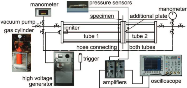
The main problem, which is considered in this work, is the investigation of plate-shell structures response due to impact loadings caused by gas mixture explosions. This rather complex phenomenon is studied in the context of its mechanical aspects. The main field of interest is the ductile fracture prediction, which occurs in impact subjected plate-shell structures during their inelastic dynamic response. This phenomenon can be assigned to the field of failure mechanics. A primary problem of this domain is associated with formulation of sufficiently simple and accurate criterion of crack initiation and propagation for both regular and singular stress concentrations in structural elements involving multiaxial stress states. The design against failure is a fundamental importance in everyday engineering practice. The area of potential applications is very wide. Starting from the assessment of safety against the damage threat posed by internal explosion on-board commercial aircrafts in the aeronautical industry, through assuring the reliability against the metallic pressurised vessels accidents caused by explosions or ductile tearing of pipelines in the industrial transport or storage of fluids, the metal-forming processes such as stamping and extrusion in aluminium and steel industries (also automotive engineering), army applications, such as a ballistic penetration – projectile impact of steel plates, finishing with the general problems of life prediction and many others. The presented work focuses on the experimental investigations, modelling and numerical simulations of the considered problem. The different model analyses, verifications and comparison studies give the field to discuss and to draw conclusions.
1.2. Aim and range
The following aim and range have been stated for this work:
The literature review concerning the area of different approaches to failure designing, especially the numerical fracture modelling in ductile materials;
Elaborating the effective subroutines (in FORTRAN for MSC.MARC system) for geometrically and physically non-linear analysis including damage and fracture criterions; Creating and executing the laboratory tests program incorporating the experiments on the plates subjected to explosions and uniaxial experiments necessary for material parameters identification;
Performing the identification of material constants for the assumed constitutive model, their verification, calibrating the fracture criterion parameters;
Creating the plate’s model;
Performing the example numerical simulations with different fracture criterions, the verifications by comparing obtained results to experiments;
The discussion of results and conclusions.
1.3. Literature review
The first studies, which have begun the scientists’ interest in the failure designing, are the works of Wieghardt [188], Inglis [82] and Griffith [71], [72] from the early 1920s. In that time Griffith has developed the original concept of fracture energy, which is assumed as the beginning of the fracture mechanics. His first hypothesis was that brittle materials contain elliptical microcracks, which introduce high stress concentrations near their tips. The Griffith’s work was ignored by the engineering community for almost thirty years. In the 1950s, the extension of his theory was provided by Irwin [83]. He extended the model to an arbitrary crack and proposed the criterion for its growth. Irwin also showed that the stress field in the area of crack tip is completely determined by the parameter K (stress intensity factor) related to the three different crack opening modes. After Irwin the further development of the Griffith’s model was continued. In 1957 McClintock and Walsh [122] introduced the friction between crack faces, in 1959 Barenblatt [16] and in 1960 Dugdale [60] made the first attempts at including the cohesive forces in the crack tip region, in 1961 Kaplan [91] focused on the possibility of applying the fracture model to concrete. In the late 1960s the first extensions to ductile fracture processes was initiated. Rice [147] showed that the energy release rate can be expressed as a path-independent line integral called the J-integral. Wells [185] proposed a parameter called crack tip opening displacement. One of the first fracture mechanics finite element applications was performed in 1976 by Hillerborg et al. [80]. They proposed the model where the constitutive relation is described by a material softening law between tensile stress and local opening, instead of a stress versus strain relation. Recent trends in fracture mechanics include dynamic investigations on nonlinear materials, fracture mechanics of microstructures and modelling related to local, global and geometry-dependent fractures.
Nowadays, fracture mechanics concerned in the lifetime analyses of structures creates a huge part in the solid mechanics domain. Unfortunately, it has still one crucial limitation. In
general, a structural fracture may be decomposed into two steps: the crack initiation, and the crack propagation. The classic fracture mechanics has been developed to study the evolution of a pre-existing crack. This causes that the stage of crack initiation in this approach is quite problematic.
While the fracture mechanics theories were being developed, in 1958 the new approach to the failure designing was formed. The pioneer of the new idea was Kachanov [88]. He introduced a damage variable to describe the microdefect density locally in a creeping material. The notation was that that damage could be measured by the volume fraction of voids. This became the fundament to continuum damage mechanics. One year later Rabatnov [146] furthered this idea with the evolution of void density equations based on the concept of effective stress in damaged materials. The first paper in English, which described the new theory, was published by Odqvist and Hult [135] in 1961. The later more known publications are Chaboche [41] in 1981 presenting the general theory and several applications to a turbine blade refractory alloy, Murakami [129] in 1983 discussing the notion and the practical procedures, Lemaitre and Chaboche [112] in 1990 the monograph of solid mechanics, containing one chapter with the description of damage theory and Lemaitre [109] in 1996 presenting a course on damage mechanics.
The key concept for this theory is the damage evolution law obtained from the thermodynamic potential and the potential of dissipation. The shape of second potential has not been well established in literature, during the theory development different damage evolution laws were proposed. The first after the pioneers was Lemaitre [111] who in 1984 introduced the most popular till now damage evolution equations for the ductile damage. After him many other models occurred: in 1986 Tai and Yang [165], in 1992 Wang [184], in 1993 Chandrakanth and Pandey [44], in 1997 Bonora [28], in 2000 Armero and Oller [9], Dhar et al. [57], in 2004 Lin et al. [114].
The continuum damage is not limited to ductility only. It was also applied in the analyses of brittle materials like rock by Shao and Khazraei [154], concrete by Fl"rez-L"pez [65], Peng and Meyer [139], Faming and Zongjin [63], Kuna-Ciska and Skrzypek [103], graphite by Kaji et al. [89], laminates and composites by Maire and Chaboche [119], Allen [3], Edlund and Volgers [61] and even of a human bone by Taylor et al. [167].
The original concept of damage mechanics was created for an isotropic material, in such case the damage variable is represented by a scalar value. At the beginning of 1980s the first efforts have been done to find realistic models to describe anisotropic damage phenomena. As the first attempt, the vectorial damage variables were introduced by Kracinovic and Fonseka
[98], [99]. In further attempts, two approaches were proposed. The general anisotropy model, where the damage variable is represented by the fourth order tensor, analyzed by Lecke and Onat [105], Chaboche [40] and Kracinovic [97] and the simplified orthotropic model, where the damage variable is represented by the second order tensor, analyzed by Murakami and Ohno [130], Chow and Wang [46], Voyiadjis and Kattan [182] and Lemaitre [110]. In the anisotropic damage modelling the effective stress tensor is usually non-symmetric. The solution avoiding a complicated theory is the symmetrisation of this tensor. Such procedure was analyzed by Lu and Chow [116] or Voyiadjis and Park [183].
The further extension of continuum damage mechanics was done by deriving a large strain theory in elastic-plastic damage analysis. In 1990 Combescure and Yin [52] proposed a generalization of the discrete Kirchhoff theory to the analysis for large displacement and large strain with some applications to damage mechanics. At the beginning of 2000s a theory for large strain in elastic-plastic damage was analyzed by Brünig [37]. He used a multiplicative decomposition of the metric transformation tensor into elastic and damage-plastic parts. In the same time Menzel and Steinmann [124] proposed a theoretical and computational model for the treatment of anisotropic damage at large strains, Kaliske et al. [90] introduced the constitutive relations for elastometric materials large strain modelling.
In the damage modelling the essential problem is the experimental identification of the damage variable evolution. The reliable measurement is still nowadays a challenging task. In 1987 Lemaitre and Dufailly [113] described possible approaches. The experimental procedures to estimate the damage evolution can be classified in two main groups direct and direct measurements, where this last group can be divided to destructive and non-destructive methods. The practical examples of identifications using the results of load-unload tensile tests were presented by Amar and Dufailly [5], Alves et al. [4], Mashayekhi et al. [120] and Ambroziak [6]. Recently this problem was also analyzed by Celentano and Chaboche [39], they proposed a new procedure of damage measurement including the correction factor eliminating the triaxial effects occurring during experimental tension tests.
The continuum damage mechanics has began the continuous, micromechanical approach in the failure designing. It made this kind of modelling more attractive then global, discontinuous approaches such as fracture mechanics because the model parameters depend on the material only, not on the geometry. The theory based on such assumptions is also better adapted to the analysis of the crack initiation in a crack-free body.
But damage mechanics is not the only approach, which has been developed on the basis of micromechanical models. Soon after the continuum damage theory pioneers in the late 1960s
McClintock [121] and Rice and Tracy [148] studied the role played by growth of microvoids in ductile fracture. This new idea has began the new group models, sometimes called the porosity models, based on the observation that ductile damage develops at microstructural level in form of voids and cavities, which may grow differently according to the plastic strain and the stress triaxiality level. From a general point of view, in these models, porosity has the major effect to shrink the material yield surface with the progression on the deterioration process. The failure was postulated to occur when the cavity radius would reach a critical value specific for the material.
On the basis of this new theory in the middle of 1970s Gurson [74], [75] developed the widely known pours ductile material model and fracture model. At the beginning of 1980s the modifications introduced by Tvergaard [172], [173] and Tvergaard and Needleman [174] made this model more complete. The initial formulation was extended to include the acceleration in the failure process induced by void coalescence. In 1985 Thomason [170] proposed the plastic limit load model for void coalescence. In 2001 Zhang [200] integrated the models of Gurson and Thomason and proposed a so-called complete Gurson model. The similar model to Gurson’s but with a slightly different dependency in the hydrostatic term was proposed by Rousselier [151] in 1987. In 1992 Besson and Abouaf [24] extended the modified Gurson model to viscoplasticity. In 1993 Gologanu et al. [70] proposed the modification by introducing a void shape parameter, which allowed considering the anisotropic damage effects in cavity based modelling. This idea was further used also by Benzerga et al. [23], Siruguet and Leblond [158].
Recently the micromechanical studies have been performed in order to correlate voids evolution and interaction with the resulting macroscale material yield function. The role of smaller size voids in a ductile damage was investigated by Tvergaard and Niordson [175] and incorporated into the Gurson model by Wen et al. [186]. The 3D voided unit cell based approach investigating the role and effects associated with the crystallographic orientation of the matrix material was analyzed by Schacht et al. [153]. Bonfoh et al. [27] used the modified Gurson theory to model damage evolution initiated by secondary included particles debonding in a policrystaline material.
The Gurson model for a single material involves over ten parameters, which need to be calibrated. The material parameters are not physically based and cannot be directly measured. Typically, an iterative calibration procedure, involving numerical simulations and experimental data is necessary. In 1998 an attempt of the parameters calibrating was made by Faleskog et al. [62], [68]. Later Rivalin et al. [149] determined the parameters by comparing
tests on experimental samples with the finite element simulation, Prahl et al. [144] used a period homogenization approach, Springmann and Kuna [160], [161] developed a non-linear optimization identification procedure.
The results of experiments performed by Shockey et al. [156] have shown that coalescence mechanism can be treated as a nucleation and growth process on a smaller scale. This simplifies the description (also identification) of the intrinsic micro-damage process by taking into account only the nucleation and growth mechanism. Such approach was used by #odygowski and Perzyna [117] in investigation of the fracture in the polycrystalline solids under dynamic loading process.
The porosity damage models are related to a specific micromechanism of failure, this is the main deference between this theory and the continuum damage models presented earlier, where damage is one of the thermodynamics variables that affect the material stiffness. One of the similarities is that both approaches are called the fully coupled, which means that the damage effect is introduced directly into the overall constitutive equations and affects all the thermomechanical fields according to the appropriate coupling theory.
The third and up till now last group in ductile failure modelling, which has been developed on the basis of micromechanical models is the approach called abrupt failure criteria. These criteria predict the occurrence of failure in the material when a chosen parameter in a model reaches its critical value or a criterion is satisfied. In this approach no coupling exists between the variable that accounts for progressive damage and other variables as strain, stress, etc. The concepts of McClintock [121] and Rice and Tracy [148], the initial studies in the porosity models, can be also joined to this group. In their work the parameter, which is characteristic and the fracture occurs when it reaches critical value is the cavity volume fraction.
During the development of abrupt failure methods many criteria have been formulated. In the 1950 Freudenthal [67] proposed the criterion of total plastic work, which postulates that the initiation and propagation of a crack is dominated by a critical value of the absorbed plastic energy. The simple criterion predicting the occurrence of failure in the moment when the equivalent plastic strain reaches a critical value was used by Datsko in 1966 [54]. In 1968 Cockcroft and Latham [51] postulated that fracture is controlled by maximum principal tensile stress integrated over the plastic strain path. This last criterion was modified in 1972 by Brozzo et al. [36], who introduced an explicit dependence on hydrostatic stress, in 1979 by Oh et al. [136], who introduced the normalization of the maximum principal tensile stress by the equivalent stress and in 1990 by Clift et al. [49], who replaced the maximum principal
tensile stress by the equivalent stress. In 1978 Norris et al. [131] proposed en empirical criterion based only on the hydrostatic stress and one material constant. In 1981 Atkins [10] modified the last criterion by introducing an explicit dependence on the deformation path. In 1985 Johnson and Cook [85] is postulated that the critical equivalent fracture strain is a monotonic function of the stress triaxiality. This model has become very popular in commercial codes, since in 1989 Johnson and Holmquist [86] published a table of material fracture data for a number of structural materials. In 2004 Bao and Wierzbicki [14], [15] studied the model based on assumption that fracture initiates at the critical point of a structure when the accumulated equivalent plastic strain with a suitable triaxiality weighing functions reaches a critical value. In this works they determined these functions in the wide range of stress triaxiality from eleven different tests. In 2005 Wierzbicki et al. [191] presented calibration and evaluation of seven most popular fracture models. In 2010 Bai and Wierzbicki [12] proposed the ductile fracture criterion, where the Mohr-Coulomb model [128], [53] is used. A large majority of the criterions presented in this group belongs to empirical methods, based on extensive test programs. Their calibration for new materials sometimes requires comprehensive series of experiments involving tensile tests on unnotched and notched bars, upsetting tests and sheer tests.
Recently, in the failure analysis new models, which links the different approaches classified in groups presented above, occurred. In 2001 Chaboche et al. [43] introduced interface damage mechanics developed as a part of continuum damage mechanics, with capabilities intermediate between the damage and fracture mechanics. The main reason of developing this model is simulating various scales of composite debonding effects, such as decohesion between matrix and fibres and delamination in laminates. In 2006 Chaboche et al. [42] proposed a continuum damage mechanics approach with plastic compressibility. This model modified the classical formalism of damage mechanics in order to describe plastic compressibility in the context of ductile damage. A new damage state variable was introduced. This variable plays role of porosity in micromechanics based approaches like Gurson’s model. In 2007 Xue [199] proposed a new damage plasticity model. Fracture is postulated to occur when the accumulated equivalent plastic strain, modified by the function of the stress triaxiality and the deviatoric state parameter reaches a limiting value equal to one. This model has a construction similar to the abrupt failure methods, however introducing additionally the material weakening mechanism into the constitutive model by coupling the yield function and associated flow rule with the damage, moves it into the coupled methods.
Since the beginning of numerical methods development researchers have tried to simulate the damage and fracture process. Many methods have been proposed to implement the presented above models.
The example of the fracture mechanics implementation is the nodal relaxation method used frequently in the finite element analysis. The crack is modelled by releasing nodes one by one in order to enable the crack tip to propagate through the mesh. This method very often is improved by the advanced remeshing techniques. The simulations of this kind were performed in 1998 by Trädegård et al. [171] using characterization of the crack tip fields strength by the value of J-integral, in 2000 and 2003 by Bouchard et al. [35], [34] applying different crack propagation criteria, in 2001 by Andersson et al. [8] using the calculation of first mode stress intensity factor, in 2008 by Souiyah et al. [159] using the displacement extrapolation method [73] to calculate the stress intensity factors.
The other technique to simulate the propagation is the cohesive element approach. The cohesive elements originate from the concept of cohesive zone [60], [17]. In these type elements the numerical separation process is described by the cohesive law, which defines the relation between crack surface traction and the surface opening displacement. This technique was used in 1994 by Xu and Needleman [197] and in 1999 by Miller et al. [126] to simulate crack growth in brittle solids, in 2005 by Cirak et al. [50] to analysis the fracture and fragmentation in thin-shells, in the same year by Zhou et al. [201] to simulate the dynamic crack propagation in brittle materials using the cohesive rate-dependent model.
In contrast to above methods, where cracks are limited to element boundaries, the extended finite element method (X-FEM) has been developed. Here the concept of the discontinuous displacement has been incorporated within a finite element formulation based on the partition of unity concept [11]. The displacement discontinuities are represented by means of additional degrees of freedom. Cracks can be located arbitrarily in the finite element mesh. The first applications of this approach were done in 1999 by Belytschko and Black [19] and Moës et al. [127]. The comprehensive survey of the extended finite element method was done by Abdelaziz and Hamouine [1]. Recently this method was used by Meschke and Dumstorff [125], Belytschko and Gracie [20], Benvenuti [22], Xu and Yuan [198].
The failure modelling approaches are based also on other methods then the finite element analysis. The two examples can be given. The first is the meshless method. Its application to the fracture prediction was proposed in 1995 by Belytschko and Lu [21]. Up till now there have been quite a few works using this method. The examples are: Hao et al. [79], Rabczuk and Belytschko [145], Bordas et al. [30], Duflot and Nguyen-Dang [59]. The second example
is the boundary element method used in the fracture mechanics: Carpinteri et al. [38], Frangi [66].
The most popular approach in the ductile fracture numerical modelling is performing analysis using the classic finite element method. The crack initiation and propagation is modelled by deactivation/deleting elements which fulfil the assumed fracture criterion. One of the firsts authors, who applied this method are Taupin et al. [166] in 1996. They simulated the blanking in the metal forming process using the McClintock criterion and compared the results with experiments, reaching a relatively good correlation. Further many others followed the same method. In 2001 Besson et al. [25] simulated the cup-cone fracture in round bars and plane strain specimens using the Gurson and Rousselier models. In 2008 Teng [169] analyzed the same phenomenon using the continuum damage mechanics. He compared his results with experiment. In 2003 Børovik et al. [32] analyzed the influence of stress triaxiality and strain rates on the basis of the tension tests performed on the smooth and notched specimens using in simulations the Johnson-Cook criterion. In 2005 Bonora et al. [29] performed similar analysis of the stress triaxial state influence. They used their own non-linear continuum damage model and compared the results of simulations with experiments. In 2007 Xue [199] simulated the tension tests of the smooth specimens with emphasis on crack path prediction using his own model.
The alternative approach to element deactivation in the finite element method is changing the material parameters in elements, which are considered as broken/damaged. Rivalin et al. [149], who analyzed ductile tearing of the pipeline-steel wide plates using the extended Gurson-Tvergaard-Needleman model, proposed replacing the behaviour of broken elements by an elastic behaviour with very low stiffness (the value of Young modulus of 1 MPa). Hambli and Badie-Levet [77] and Hambli [76], who simulated fracture prediction during extrusion and sheet-metal blanking process using the continuous damage mechanics, proposed increasing abruptly in the damaged elements the value of damage parameter from critical to the value near 1, decreasing considerably their stiffness.
The extension of presented approach is applying the adaptive remeshing to the finite element method. This additional procedure is due to the large geometrical distortion of finite elements and the adaptation to the physical behaviour of the solution. Recently this kind of analysis became very popular. In 2002 Børovik et al. [33] presented the simulation of the thick steel plates perforation with the different shape noses using the continuum damage model with own modifications. The simulations were performed with fixed and adaptive mesh, the results were compared with experiments reaching close correlation. In the same
year, Borouchaki et al. [31] used adaptation of the element size with respect to the damage in metal forming fracture prediction. In 2005 Lee and Wierzbicki [107] simulated fracture prediction of thin plates under localized impulsive loading. They compared analytical and numerical solutions for discing and petalling phenomena. In numerical analysis they used Bao and Wierzbicki fracture criterion and both fixed and adaptive mesh methods. In 2008 Labergere et al. [104] and Saanouni [152] used this method in simulation of metal forming using the continuum damage mechanics.
The finite element method is nowadays the most popular and powerful tool in mechanics, including the damage and fracture analysis. A large majority of researchers use this method in the local approach, unfortunately sometimes it causes problems. One of them is the pathological localization and mesh dependence associated with materials softening. This problem is essential in quasi-brittle materials but also important in the ductile failure. The solution, which attempts to overcome this problem, is applying the non-local models including the regularization techniques. The examples of such approach are the works of #odygowski and Perzyna [118], who used the relaxation time as a regularization parameter in thermoviscoplasticity theory, Addessi et al. [2], who analyzed a plastic non-local damage model for cementious materials, Rodriguez-Ferran et al. [150], who proposed a new damage model based on non-local displacements and presented two versions of application: integral-type and gradient, Mediavilla et al. [123], who introduced the discrete crack modelling of ductile fracture driven by non-local softening plasticity.
The present work focuses attention on the experimental and numerical investigation on the behaviour of circular metallic plates subjected to impulse loadings. The problem of plates responses to dynamic loads have been already analyzed by many authors. The first studies were concerned on experimental and analytical analysis of permanent deformations in plates subjected to uniformly distributed impulses. Florence [64] in 1966 performed an analytical solution for simply supported circular plates based on the bending theory of rigid-plastic plates and compared results to experiments. Jones [87] in 1968 considered taking into account membrane stresses in a study of simply supported circular plates. Wierzbicki [190] in 1954, Perrone [141] in 1967, Kelley and Wilshaw [92] in 1968, Wierzbicki and Florence [192] in 1970 considered in analysis a viscoplastic theory taking into account the large deflections and strain rate sensitivity comparing results with experiments. The displacement of the plate’s centre as a function of time during dynamic response on explosive loadings was examined by Duffey [58] in 1967. Bodner and Symonds [26], Symonds and Chon [164] both in 1979 applied the mode approximation technique to simulate large deflections of viscoplastic
structures and compared results with experiments on circular plates loaded impulsively. Nurick [132] in 1985 proposed a new experimental technique involving the use of light interference, which improved the deflection time history measurement of plates subjected impulsively. Nurick and Martin [133] in 1989 discussed their experimental results and presented an empirical relationship between the deflection-thickness ratio and a function of impulse, plate geometry, plate dimensions and material properties. The dynamic response of shock wave subjected plates was also analyzed by Pennetier and Renard [140] in 1998, K osowski et al. [96] in 2000, Woznica and K osowski [195] in 2000, Woznica et al. [196], Jacinto et al. [84], Stoffel et al. [163] all in 2001, Veldman [180] in 2006, Wi!niewski et al. [194] in 2007 and many others.
Recently more often, beside the dynamic response, also the fracture prediction in plates is investigated. Teeling-Smith and Nurick [168] in 1991 performed experiments conducted on fully clamped circular mild steel plates subjected to a uniformly distributed impulse and analyzed numerically the deformation and tearing. Olson et al. [137] in 1993 analyzed the experimental and numerical results of the fracture initiation in clamped square mild steel plates subjected to uniformly distributed blast pressure loading. Wierzbicki [189] in 1999 presented analytical solutions for plate’s petalling under explosive and impact loading. Kreja et al. [102] in 2001, Kreja and Schmidt [101] in 2004 modelled the plastic ductile damage evolution and collapse of plates and shells in the quasi-static conditions. Shen [155] in 2002 studied experimentally and theoretically the failure of circular plates struck by masses. Lee et al. [108] in 2004 analyzed numerically the fracture in thin plates under hemi-spherical punch. Day et al. [56] in 2006 performed the fracture experiments on projectile impact of steel plates. Daudonnet [55] in 2006 considered in numerical analysis the fracture of plates subjected to explosions. Stoffel [162] in 2007 analyzed the anisotropic ductile damage and failure of shock wave-loaded plates. Veldman [179] in 2008 investigated experimentally the effects of pre-pressurization on fracture in blast-loaded reinforced rectangular aluminium plates. P$cherski et al. [143] in 2009 studied the effect of strain rate on ductile fracture in the dynamic double shear tests with thermographic observations.
The author is aware of the fact that the presented literature review does not exhaust the full state of art in the analyzed field. Despite the relatively young age of this solid mechanics sub-discipline in the last decades high interests among researchers caused very fast development. The intention of the author of this review is to present the approaches which had significant influence on the discipline evolution and which are widely used in the fracture
modelling. For each mentioned method only a limited number of publications is presented, of course those are only examples among many others.
2. Theoretical foundations
2.1. Abstract
This chapter contains the description of models, which are in common use in damage and fracture mechanics analysis. Firstly, the assumed constitutive model is presented. Further, the examples of different approaches to the failure modelling are discussed. Four main groups are here distinguished and described: fracture mechanics, continuum damage mechanics, the porous solids plasticity models and the abrupt failure criteria. The selection of models, which are considered in further analysis, is finally done.
2.2. Introduction
One of the main parts of this work is the numerical simulation of the plates subjected to impact loadings. The plates are submitted to large plastic deformations and fracture. Such analysis requires applying non-linear material models. Initially, an appropriate constitutive law should be chosen. The author used the earlier experiences of the researchers who were interested in the shock wave-loaded plates behaviour analysis: K osowski et al. [96], Woznica and Klosowski [195], Woznica et al. [196], Stoffel [162], Stoffel et al. [163], and decided to use, descended from the model of Perzyna [142], the viscoplastic model proposed by Chaboche [112]. This model was successfully employed by the mentioned authors. Its main advantage is universality. Of course before application to the current problem an appropriate identification of material parameters and its results verification should be performed. Secondly, the choice of a suitable fracture model and criterion describing correctly the initiation and propagation of cracks should be done. Here different approaches are considered, some of them are chosen to the numerical analysis applications.
2.3. Constitutive model
The chosen constitutive model in the considered study is based on two main assumptions: the material is isotropic and the strains are small. The second condition allows employing the additive decomposition of the strain rate into its elastic and inelastic parts
E I ! "
, (2.1)
where is the total strain rate, E
and I
State variables
Associated variables Observable variables Internal variables
Elasticity Temperature, T Specific entropy, S
Total strain, Stress, !
Viscoplasticity
Inelastic strain, I Stress, ! Isotropic hardening, r Isotropic hardening
stress, R Kinematic
hardening, "
Kinematic hardening stress, X Tab. 2-1. Summary of the state and associate variables
The derivation of the constitutive equation for a given material can be done in the framework of the thermodynamics of irreversible phenomena through a certain number of so-called state variables. These variables distinguished into observable and internal and their associated variables are presented in Tab. 2-1. For the material characterization introducing the thermodynamic potential, from which the state laws can be derived, is necessary. Usually the Helmholtz free energy # , which is a scalar function of all state variables, is used. The , expression of the state potential can be determined taking into account the state coupling between variables. It is possible to uncouple the state potential into the elastic behaviour and inelastic (hardening), with the specific free energy being decomposed as
( , ) (a, , ).
E E I
T r T
# !# "# (2.2)
The elastic part of the free energy function can be expressed as follows
$
1/ 2%
$
: :%
,E E E
# ! & a (2.3)
where is the material density, a is an elasticity tensor. By the definition of the associated variable, the stress can be derived from the potential !E to give the law of state
: . E E E
#
&
' ! ! ' a ! (2.4)The elastic strain can be evaluated by reversing the equation (2.4)
$ %
1
,
ETr
E
E
(
(
"
!
)
!
!
!
I
(2.5)where E is the elastic modulus, " is the Poisson’s ratio and I is the metric tensor.
The thermodynamic state potential allows writing relations between observable state variables and associated variables. For the internal variables it allows only to definite their associated variables. To describe the evolution of the internal variables (the dissipation
process) the dissipation potential function (a positive convex function of associated thermodynamic variables) ** is needed
*
( , , ).
R
*
! +
!
X
(2.6)The complementary law of evolution is expressed by the normality property
.
I '+
!
'! (2.7)
To describe the evolution of the inelastic strain the viscoplastic constitutive Chaboche model was chosen. In this model the dissipation function
,
+,is defined as$
%
1 3 2 ' ' , ( ) , 1 n ij ij ij J R k K J a a a n K " ) ) ) + ! ! " X ! (2.8)where !' and
X
'
are the deviatoric parts of the stress and kinematic hardening tensors, respectively, k is the initial yield stress,K
and n are the viscous material parameters. Theangle brackets
x
are referred to the McCauley brackets:x
!
12(
x
"
x
)
.The inelastic strain rate is derived from the equation (2.7) earlier substituted by (2.8)
$
%
3 ' ' , 2 ' ' I p J ) ! ) X X ! ! (2.9)where accumulated plastic strain rate p is given by
$
' '%
. n J R k p K ) ) ) ! ! X (2.10)The kinematic hardening tensor X and the isotropic hardening scalar R are expressed as
1
2
,
(
) ,
3
Ia
c p
R b R
R p
!
)
!
)
X
X
(2.11)where a, c, b and R1 are hardening material parameters.
2.4. Damage and fracture models
2.4.1. Fracture mechanics
In the fracture mechanics field of interest are all kind of defects understood as the stress concentrators in the form of cracks, flaws or notches. The problem is to study an influence of applied loads, defects geometry, environmental conditions and a material behaviour on the fracture process in solids. The fracture mechanics is the powerful tool in the crack
propagation analysis but it avoids the problem of the crack initiation, which is very important for this work. That is why only the brief review of these mechanics field foundations are presented here.
The first approach in the fracture mechanics is the energy criterion, which states that the crack extension occurs when the energy available for the crack growth is sufficient to overcome the resistance of a material. This approach was proposed by Griffith [71], [72] and later developed by Irwin [83]. For example, in an infinite plate presented in Fig. 2-1, subjected to remote tensile stress for the crack of length 2a the energy realise rate G is given by [7] 2 . e a G E
!
" (2.12)At the moment of fracture Ge = Gec = 2
#
, where Gec is the critical energy realise rate – thematerial’s resistance to fracture and
#
$ is the energy necessary to create the unit of a free surface.Fig. 2-1. Infinite plate with the elliptic crack under tension stress
The alternative to energy criterion is the stress intensity approach based on the stress function used to determination of the stress and displacement field near the crack tip proposed by Westergaard [187]. In this approach three ways of applying a force to enable a crack to propagate are distinguished (Fig. 2-2):
mode I – opening, a tensile stress normal to the plane of the crack,
mode II – sliding, a shear stress acting parallel to the plane of the crack and perpendicular to the crack front,
mode III – tearing, a shear stress acting parallel to the plane of the crack and parallel to the crack front.
Fig. 2-2. Types of cracks loadings
For each type of the crack loading the following stress field responds [7]
% &
, , , , 2 T T T ij ij K f T I II III r!
"'
" (2.13)where r and
'
$are the polar coordinates with the beginning point in the crack tip, KT is thestress intensity factor for each type of the crack.
As the example the stress and displacement fields near the tip of mode I crack in the infinite plate under plane-stress conditions, shown in Fig. 2-3, are presented.
Fig. 2-3. Stress field near the crack tip in infinite plate
The stress components are expressed by the following formulas
3
cos 1 sin sin ,
2 2 2
2
3
cos 1 sin sin ,
2 2 2
2
3
cos sin cos .
2 2 2 2 I 11 I 22 I 12 K r K r K r
'
'
'
!
'
'
'
!
'
'
'
(
) * " , + -. / ) * " , 0 -. / " (2.14)%
&
%
&
%
&
%
&
cos 3 1 cos , 2 2 sin 3 1 cos . 2 2 I 1 I 2 K r u E K r u E'
1
1
'
'
1
1
'
" + + 0 " + + 0 (2.15)The stress intensity factor in this case is given by
.
I
K
"
!
a
(2.16)The displacement of crack edges in its area (Fig. 2-4) is defined by
!
2 2 1 2 . 2 u a x E!
" + (2.17)The maximum displacement called the crack opening displacement COD occurs in the half length of the crack
4 .
COD a
E
!
" (2.18)
Fig. 2-4. Crack edges displacement
Of course, for the other crack types, body dimensions and stress conditions different formulas not discussed here describing the stress and displacement fields are necessary.
In the stress intensity approach the failure occurs when KI = KIc, where KIc is a fracture
toughness (a measure of material resistance) determined by experiments.
The energy and stress intensity approaches represents the methods of linear elastic fracture mechanics, the extension to the plasticity was proposed by Rice [147], who applied the path-independent J-integral to the analysis of conditions for a crack propagation. The integral is defined as follows (Fig. 2-5)
2 1 , J Wdx ds x 2 ) 3 * " , + -3 . /
4
p u (2.19)where 2 denotes a curve surrounding the crack tip,
p
is the surface force vector, u is the displacement vector and W is the strain energy density0 : .
W "
4
! d (2.20)The physical interpretation of the J-integral is the rate of change of potential energy with respect to the incremental change of the crack length.
Fig. 2-5. Two-dimensional cracked body
The J-integral in the non-linear fracture mechanics has a similar task as the stress intensity factor in the linear mechanics. It determinates the field of stress near the crack tip. As the J-integral is path-independent, usually the easiest possible contour 25 which is the circle with radius r, is being chosen. In such case the stress field is given by the following formula [69]
%
&
1 1 n , , n ij o ij o o J n l r!
!
! '
6! 7
0 ) * " , -. / " (2.21)where
!
o,6
, n are the material constants, 7o "!o E, ln is the constant depending on n and ij!" is the nondimensional function of
'
depending on n, the crack type, and the stress state.2.4.2. Continuum damage mechanics
The continuum damage mechanics has began the continuous, micromechanical approach in the failure analysis. This theory gives a possibility of simulating the crack initiation and propagation. It is fully coupled with the constitutive law that affects the weakening of the material stiffness. This approach is chosen for further analysis in this work, that is why the detailed description including coupling with the Chaboche constitutive model is presented.
The continuum damage mechanics is based on the statement that the damage is mainly the process of initiation and growth of microcracks and cavities in a material’s structure. This process is mechanically represented by the damage variable D proposed by Kachanov [88].
Fig. 2-6. Damaged body
Considering a volume element in a damaged body presented in Fig. 2-6 at macro-scale, that is of a size large enough to contain many defects and small enough to be considered as a material point of mechanics of continua, and a plane cross-section defined by its normal vector n, the damage variable D(n)can be expressed as
( ) ( ) ( ) , n D n n S D S " (2.22)
where S(n) is the area of the intersection of the plane with the volume element and ( )n D
S is the effective area of the intersection of all microcracks or cavities which lie on ( )n
S .
According to this definition, the damage variable depends on the choice of the normal n, therefore a tensor formulation for this parameter should be used. Assuming the isotropy of damage, which means uniform distribution of cracks and cavities in all directions, D(n)does not depend upon n and becomes a scalar value D, which is bounded by the values of 0 (undamaged material) and 1 (fully broken).
Fig. 2-7. Damaged body at uniaxial loading state
The important step in development of the continuum damage theory was introducing the concept of effective stress by Rabotonov [146]. Considering a volume element in uniaxial loading conditions, presented in Fig. 2-7, usually the stress is calculated as
,
F
S
but if the material is damaged and the defects are open, no microforces acts on the surfaces of microcracks or cavities represented by SD, then the stress should be related to the effective
surface
S
"
" +
S S
D, thus the effective stress are defined as . D F S S!
" + " (2.24)Introducing to this equation the damage variable definition (2.22) the effective stress
!
" areexpressed as
.
1 D
!
!
"
+
"
(2.25)At this stage of theory development for each type of defect and mechanism of damage a micromechanical analysis should be done. To avoid this problem Lemaitre [109] proposed the strain equivalence principle. The statement postulated that every strain behaviour of a damaged material is represented by constitutive equations of an undamaged material in the potential of which the stress is simply replaced by the effective stresses.
The defined damage variable D is a new internal variable considered in the framework of the thermodynamics. Its associated variable is the damage energy release rate Y. Both complement variables presented in Tab. 2-1. The extended state potential in the form of decomposed free energy is expressed as
( , , ) ( , , ).
E E I
T D r T
8 8" 08 " (2.26)
The elastic part of the free energy including damage has the following form
%
1&
%
&
: : . 2 E D E E 8 9 + " a (2.27)According to the strain equivalence principle the stress component can be calculated as
%
1&
: . E E E D8
9
3 " + 3 a !# (2.28)After reversing the equation (2.28) the elastic strain are expressed as
% &
Tr 1 . 1 1 E E D E D1
1
0 " + + + I ! ! (2.29)By the definition of the associated variable, the damage strain energy release rate can be derived from the potential E [109]
1 : : . 2 E E E Y D
8
9
3 " " + 3 a (2.30)Considering WE as the density of the elastic strain energy
1
(1
) : : ,
2
E E E EW
"
4
!$
d
"
+
D
a
(2.31)we can establish the relation between Y and WE
.
1
EW
Y
D
+ "
+
(2.32)Splitting the density of the elastic strain energy WE into two parts: the shear energy part and
the hydrostatic energy part and using the law of linear isotropic elasticity coupled with damage [109] the final formula for the damage strain energy release rate can be obtained
2 2 , 2(1 ) eq Y R D E 1
!
+ " + (2.33)where R1 is the triaxiality function
2
2
(1
) 3(1 2 )
,
3
H eqR
11
1
!
!
)
*
"
0 0
+
,
,
-
-.
/
(2.34)where ! !H eq is the stress traxiality ratio, which contains !eq the Huber-Misses equivalent stress and !H the hydrostatic stress, expressed as
% &
% &
% &
1 2 3 1 1 1 Tr : Tr , Tr . 2 3 3 3 eq H ! ":< ), + * )- , + *-;= ! " . / . / > ! ! I ! ! I ? ! (2.35)
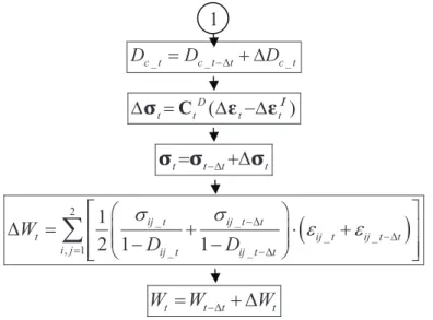
To describe the evolution of the damage variable the dissipation potential function including damage is needed. In case of viscoplastic and damage effects, it is possible to note from experimental observation that damage does not depend explicitly upon !, R, X. Therefore, it is possible to separate the dissipation effect in damage and the viscoplastic flow contribution [28]
* D( , , ) I( , , , ).
Y p D R D
@ "@ # 0@ ! X (2.36)
The damage evolution is expressed by the generalized normality law
, D D Y
@
A
3 " + 3 # # (2.37)where A# is the plasticity multiplier expressed as
%
1
&
.
p
D
To describe the evolution of the damage variable the isotropic damage model proposed by Lemaitre was chosen [109], [111]. The dissipation function @D is written as a power function of Y
%
11&
, 1 s D S Y D s S B@
0 + + ) * " , - + 0 . / (2.39)where S, s and
B
are damage material parameters. The evolution of the damage variable is derived from the equation (2.37) earlier substituted by (2.38) and (2.39)%
&
1 1 . s Y D p D S B + 0 ) * " +, - + . / # # (2.40)The dissipation function @I for the Chaboche model coupled with damage is defined as
%
& %
&
%
&
1 ' ' / 1 ( , , , ) . 1 n I K J D R k R D n K@
0 + + + + " C " 0 X X ! ! (2.41)The inelastic strain rate derived from equation (2.7) earlier substituted by (2.41) has the following form
%
&
3 ' ' , 2 ' ' I p J + " + X X ! ! # # (2.42)where the accumulated plastic strain rate p# is given by
%
& %
&
%
' ' / 1&
. n J D R k p K + + + + " ! X # (2.43)Both kinematic and isotropic hardening formulas have the same form as in the model without damage – equations (2.11).
The fracture in the continuum damage mechanics model occurs when the damage variable reaches a critical value Dcr, which depends on the material and the stress state. In the uniaxial
stress state the critical value of damage is considered as a material parameter D1cr, which can be identified from the pure tension test. In three dimensions the fracture criterion is given by the following formula
2 1 *2 1, u cr cr D D ! ! " D " (2.44)
where!u is the ultimate stress – the maximum value of stress obtained in the tension test and
*
%
&
* 1 2. 1 eq R D 1!
!
" + " (2.45)2.4.3. Porous solid plasticity models
The porous plasticity models are based on the assumption that the effect of ductile damage is taken into account in the yield condition by a porosity term that progressively shrinks the yield surface. The first in this group is the model proposed by Gurson [75], [74]. He derived this model from the Rice and Tracey [148] analysis of an isolated void. The damage variable in this approach corresponds with the void volume fraction or porosity denoted as f. In the model initial formulation the yield surface E is given by the following expression
% &
2 2 0 0 Tr 2 cosh 1 0, 2 eq f f ! ! ! ) * ) * E ", - 0 , -+ + " . / . / ! (2.46)where !0 is the flow stress of the matrix material.
The most popular version of the Gurson’s model is the extended approach proposed by Tvergaard and Needleman [174]. The modified model includes not only the nucleation and growth of the voids as the origin version but also their coalescence, which induces the acceleration in the failure process. In this model the isotropic damage is represented by the effective porosity *
f . The Gurson’s yield surface is generalized in the following form [200]
% &
%
&
2 2 2 * * 1 1 0 0 Tr 2 cosh 1 0, 2 eq q q f q f ! ! ! ) * ) * E ", - 0 , -+ + " . / . / ! (2.47)where q1 and q2 are the material coefficients which are assumed to be constant. The effective porosity function *
f accounts for the effects of rapid void coalescence [200]
%
&%
&
%
&
* 1 if , 1 if , c c c c f c c f f f f f q f f f f f f f F GH " I 0 + + + J HK (2.48)
where fc is the volume fraction of voids at which the void coalescence starts and ff is the
void volume fraction at final fracture.
The evolution of f is the sum of the nucleation contribution fn and the growth of existing
voids fg
.
n g
The void nucleation law generally is taken as
%
&
, In eq m eq
f# " A7# 0B !# 0!# (2.50) where A and B are the strain and stress controlled void nucleation intensity, respectively, I
eq
7# is
the equivalent plastic strain rate, !#m is the mean normal stress rate.
The growth of existing voids law generally is written as
%
1&
Tr% &
I .g
f# " + f # (2.51)
In this model the material loses all stress-carrying capacity – the fracture occurs, when
f
f L f and f* L1q1.
The Gurson model contains up to ten material constants which should be identified before application. Some of them are not physically based and cannot be directly measured for a material. For example, the parameters q1and q2 governing the voids growth and the parameter
c
f should be determined from numerical micromechanics analysis, the initial void volume
fraction and the nucleation parameters can be estimated only from micrographs analysis at different states of deformation. Such complicated identification causes problems in applications with a specific material for which parameters have not been estimated before by other researchers.
Similar to the Gurson’s model, the damage is also represented by the porosity variable f ,
in the model proposed by Rousselier [151]. The difference is that Rousselier based his model on the thermodynamical considerations whereas the first one was derived from the micromechanical description of the porous material. This model’s description is omitted, as well as the further development of this both representative approaches for the porous plasticity methods, as these models are not chosen for further applications in the present work.
2.4.4. Abrupt failure criteria
In the abrupt failure criteria approach the fracture is predicted to occur when one chosen variable, uncoupled from other internal variables, reaches its critical value. Those criteria are relatively simple and very often based on recourse of experimental data. One of the first examples is the criterion, which origin comes from the Huber’s strength of materials theory [81] formulated at the beginning of 20th century, postulating that the fracture occurs when the
equivalent plastic strain 7 reaches a critical value I I
f
7
(the equivalent plastic strain at fracture),
I I
f
7 " 7 (2.52)
where for incompressible plastic material 7 is defined as I
% & % & % &
2 2 21 2 3 2 3 , I I I I
7
"7
07
07
(2.53) where7
1I, 2 I7
and7
3I are the principal plastic strains.In the further development of this approach it has been accepted that generally the criteria should take into account the deformation path, because the current state of the material is not enough to characterise damage [51], [131], [10]. Therefore, fracture criteria should be expressed in general form as
%
&
* * 0 process parameters , f C "4
7 f d7 (2.54)where 7 is usually the equivalent, total or plastic strain and * *
f
7 is the value of this strain at failure.
One of the first criterions formulated in this form is the Freudenthal’s approach [67], based on micromechanics, which postulates that the fracture is dominated by a critical value of the plastic work I
W 0 . I f I I eq C "W "
4
7 ! d7 (2.55)The alternative to previous one, is the criterion of maximum plastic shear work considered by Lee and Shaffer [106]
max max
0 ,
I
f xy I xy
C"
4
# ( d# (2.56)where (maxxy is the maximum shear stress in plane xy,
max
I xy
# is the maximum plastic shear strain
in plane xy and I f
# is the maximum plastic shear strain at failure.
Cockcroft and Latham assumed that the maximum principal stress ! is the most relevant 1 in the initiation of fracture
1
0 .
I
f I
![Fig. 2-8. Dependence of the equivalent plastic strain at fracture on the stress triaxiality [13]](https://thumb-eu.123doks.com/thumbv2/123doknet/14537127.724238/37.892.297.554.509.722/fig-dependence-equivalent-plastic-strain-fracture-stress-triaxiality.webp)