HAL Id: hal-02389726
https://hal.archives-ouvertes.fr/hal-02389726
Submitted on 2 Dec 2019HAL is a multi-disciplinary open access archive for the deposit and dissemination of sci-entific research documents, whether they are pub-lished or not. The documents may come from teaching and research institutions in France or abroad, or from public or private research centers.
L’archive ouverte pluridisciplinaire HAL, est destinée au dépôt et à la diffusion de documents scientifiques de niveau recherche, publiés ou non, émanant des établissements d’enseignement et de recherche français ou étrangers, des laboratoires publics ou privés.
Digital Human Modeling for Collaborative Robotics
Pauline Maurice, Vincent Padois, Yvan Measson, Philippe Bidaud
To cite this version:
Pauline Maurice, Vincent Padois, Yvan Measson, Philippe Bidaud. Digital Human Modeling for Collaborative Robotics. DHM and Posturography, 2019. �hal-02389726�
Digital Human Modeling for Collaborative Robotics
Pauline Maurice
1, Vincent Padois
2, Yvan Measson
3, Philippe Bidaud
2,41Université de Lorraine, CNRS, Inria, LORIA, F-54000 Nancy, France
2Sorbonne Université, CNRS UMR 7222, Institut des Systèmes Intelligents et de Robotique, ISIR, F-75005 Paris,
France
3CEA, LIST, Interactive Robotics Laboratory, Gif-sur-Yvette, F-91191 4ONERA, 91123 Palaiseau, France
Abstract: Work-related musculoskeletal disorders in industry represent a major health problem in many
developed countries. Collaborative robotics, which allows the joint manipulation of objects by both a robot and a person, is a possible solution. But efficiently designing such assistive robots requires to assess the ergonomic benefit they offer. Similarly to other domains such as automotive or workstation design, the use of a digital human simulation (DHS) can cut down the development cost and time by replacing the physical mock-up with a virtual one easier to modify. However, simulating human-robot collaborative tasks poses specific challenges because the human and the robot form a highly coupled dynamic system in which the motion of each partner depends on the forces exchanged. Therefore a dynamic simulation is required to obtain reliable measurements for ergonomic assessments. The first part of this chapter details the challenges of DHS for collaborative robotics. State-of-the-art work on DHS with collaborative robots is reviewed to identify which questions currently remain open. An optimization-based controller is then proposed to animate a digital human model (DHM) in the context of human-robot collaboration. The second part of this chapter presents an application of the DHM controller. A human-robot collaborative task is successfully simulated and allows to quantify the effect of kinematic, dynamic and control parameters of the robot on the DHM posture and effort.
Keywords: digital human model, collaborative robotics, dynamic simulation, human-robot physical
interaction, ergonomics, robot design, human motion simulation.
Introduction
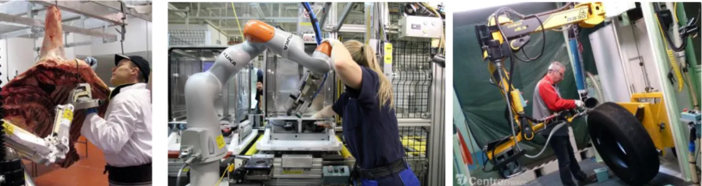
Work-related musculoskeletal disorders (WMSDs) are the first cause of occupational diseases in developed countries (Schneider, 2010; Parent-Thirion, 2012; US Department of Labor, 2016). They represent a major health issue and a significant cost for companies. WMSDs develop when biomechanical demands at work repeatedly exceed workers’ physical capacity (Punnett, 2004). Despite growing automation, numerous strenuous tasks cannot be fully automatized, at all or at a reasonable cost. With the increase of product variants built at the same assembly line associated to small order sizes, human flexibility and cognitive skills remain needed. In such situations, collaborative robotics has the potential to reduce workers exposure to WMSDs risk factors, while keeping them in control of the task execution (Krüger, 2009; Schmidtler, 2015). Collaborative robotics takes multiple forms, from shared workspace, where a human and a robot work side-by-side without physical separation, to direct physical interaction where a human and a robot cooperatively work on a common task (co-manipulation, Fig. 1). Specifically, co-manipulation robots can provide a variety of benefits, such as strength enhancement, weight compensation or movement guidance (Colgate, 2003).
Figure 1: Examples of collaborative robots for industrial applications. Left: HookAssist (Kinea Design) for beef boning. Center: Lightweight robot (KUKA). Right: Cobot 7A.15 (RB3D) for tire retreading.
Alleviating workers’ physical load is among the primary goals of the deployment of collaborative robots in workplaces. Yet, the efficacy of a collaborative robot regarding the reduction of WMSDs risks is highly task-dependent. Faber et al. list ergonomic requirements and standards for human-robot physical cooperation (Faber, 2015). However standards provide non task-specific thresholds: they serve to guarantee safety and integrity, not to optimize the benefit provided by a robot. Therefore, when designing either a dedicated robot or a workstation including a collaborative robot, an ergonomic assessment of the robot-worker system should be performed throughout the design process. Such an assessment is however hardly ever carried out, because of the lack of appropriate tools.
Ergonomic assessments traditionally rely on pen-and-paper worksheets filled by experts observing operators at work (e.g. Rapid Upper-Limb Assessment RULA, European Assembly Worksheet EAWS) (Li, 1999; David, 2005; McAtamney, 1993; Schaub, 2013). However digital evaluations now tend to replace physical evaluations in domains such as vehicle and workstation design (Chaffin, 2007). Digital evaluations rely on a digital human model (DHM) to simulate the human operator within a CAD model on the environment, and thereby offer several advantages over their physical counterparts. Digital human simulation (DHS) allows testing various human morphologies without having to recruit a wide variety of participants. Furthermore, within an iterative design process, modifications of the prototype are easier and cheaper to implement on a virtual mock-up compared to a physical one. Thus, despite an initial additional cost due to the animation development time, DHS reduces final design costs (Chaffin, 2007). These advantages make DHS a promising tool for designing collaborative robots or collaborative workstations. DHS of a human-robot system would allow a company to test several existing robots in order to identify the best-suited for a specific application, without having to buy all these robots. When designing a new robot from scratch, DHS would leave engineers more freedom to explore innovative designs by removing the constraint of building a new physical prototype every time a parameter of the mechanical structure is updated.
Requirements of DHS for collaborative robotics
DHS is now commonly used to design and evaluate workstations and vehicles. Many commercially available DHS software embed ergonomic modules (e.g. Jack (Raschke, 2004), Delmia (ref missing), EMA (Fritzsche, 2011), RAMSIS (Seidl, 2004), IMMA (Högberg, 2016)). Yet, a DHS for assessing the ergonomic benefit provided by a robot physically interacting with a human must implement some specific features.
Simulation of robot motion
The CAD model of the robot needs to be included in the simulation framework and animated. Many DHS software enable the simulation of moving elements, thereby allowing reachability, collision and operating time analysis of human-robot collaborative workstations. Ruiz Castro et al. present an ergonomic assessment of a human-robot welding task with IMMA (Ruiz Castro, 2017). Busch et al. address the question of planning a robot trajectory that minimizes physical stress on the worker (Busch, 2013). However both studies only address shared workspace: none of the task involves direct physical interaction between the human and the robot, so robot trajectories are entirely preplanned.
Conversely co-manipulation robots involve force exchange between the human and the robot, either directly or through a co-manipulated object. The motion of the robot is rarely fully preplanned, but instead depends on the force the human applies on it. The simulation should therefore allow such interactive force-dependent behaviors. Ore et al. use IMMA to compare productivity and ergonomics of an assembly task performed by a worker alone, by an industrial robot alone, and jointly by a worker and a robot (Ore, 2015). In the collaborative scenario, the robot motion is controlled by the worker through force sensors in the robot joints. However, the force-dependent behavior is limited to the robot since the generation of the DHM movement in IMMA is based on kinematics (Högberg, 2016).
Simulation of human motion
In co-manipulation, the human-robot force exchange also affects the human motion, whether because moving the robot requires additional effort, or because the robot alleviates the physical load on the worker (e.g. robots providing strength enhancement or weight compensation). Currently, most DHM animation techniques rely on kinematics only, thus ignoring the inertial properties of the human body and the effect of an external load. In addition, many DHM software provide a library of predefined behaviors such as walk,
grasp, reach. However those movements become unrealistic when loading conditions change, which is common in human-robot co-manipulation (the force exchanged is not constant). The DHM software Jack also provides a module for posture optimization which takes external force into account. However only static forces are considered while dynamic forces are ignored. Yet, co-manipulation robots can be powerful thus heavy; due to the high inertia, moving/stopping such a robot may require additional effort from the human (dedicated control laws are designed to compensate these phenomena, but the compensation is never perfect and the robot is not fully backdrivable). Therefore considering dynamic forces is needed to generate a realistic DHM movement in a human-robot co-manipulation scenario.
Alternatively, many DHS software enable importing motion capture data to animate the DHM. However the movement is realistic only if the human participant and the avatar experience a similar environment, especially in terms of interaction force. The participant must therefore be placed in a virtual reality set-up and provided with force feedback. Dombrowski et al. use such a set-up with Delmia to simulate a human-robot collaborative task on an automotive assembly line (Dombrowski, 2017). However motion capture based animation requires heavy instrumentation of the participants and is therefore highly time and resource consuming.
Concurrently to DHS software for workstation design, biomechanical software such as OpenSim (Delp, 2007) or AnyBody (Damsgaard, 2006) provide detailed musculoskeletal models of the human body. These software can generate DHM movements based on optimization of muscle activation and forward dynamics. The resulting movement is more realistic than with kinematic techniques, but the computation time is much longer. Furthermore, interactive control laws of collaborative robots cannot be simulated in these software. Thus, despite the diversity of software that exist for simulating human activity, none of them is suitable to analyze a task involving a human and a collaborative robot working together. The main limitation of existing software is that they do not provide dynamic simulation, which is necessary to obtain realistic movements of the robot and of the DHM.
DHM controller for human-robot dynamic simulation
In order to circumvent the aforementioned limitations of existing DHM animation techniques, we propose to apply a control technique traditionally used in humanoid robotics. The motion of the DHM is computed by solving an optimization problem to find the actuation variables (joint torques and contact forces) which enable to follow some objectives at best (e.g. hand or foot trajectory, hand force), while respecting physical and biomechanical constraints. Unlike analytical control techniques (Sentis, 2006), optimization techniques explicitly guarantee that both equality and inequality constraints are respected (Abe, 2007; Kanoun, 2009; Salini, 2011; Escande, 2014). De Magistris et al. already proposed an optimization-based controller for DHM animation (De Magistris, 2013). However it is based on a Jacobian-transpose method which does not guarantee the optimality of the solution, because joint torques limits cannot be explicitly included in the optimization.
LQP Controller
In this work, we use a linear quadratic programming (LQP) controller framework developed by Salini et al. (Salini, 2011). Linear quadratic programming handles the optimization of a quadratic objective that depends on several variables, subjected to linear equality and inequality constraints. The control problem is formulated as follows:
argmin
𝕏 ∑ 𝜔𝑖 𝑇𝑖 (𝕏
) 𝑖𝑠. 𝑡. {
𝑀(𝒒)𝝂̇ + 𝑪(𝒒, 𝝂) + 𝒈(𝒒) = 𝑆𝝉 − ∑ 𝐽
𝑐𝑗 𝑇(𝒒)𝒘
𝒄𝒋 𝑗𝐺𝕏 ≤ 𝐡
where τ is the vector of joint torques, wcj the contact wrench of the j-th contact point (ground reaction force and human-robot interaction force), q the generalized coordinates of the system (joint angles), ν the
generalized velocity concatenating the free-floating base twist and the joint velocities q̇, and
𝕏
=(τT,wcT,𝝂̇𝑇)T. The equality constraint corresponds to the equation of motion. Including it in the list of constraints guarantees the dynamic consistency of the resulting movement. M is the inertia matrix of the system, C the vector of centrifugal and Coriolis forces, g the vector of gravity forces, S the actuation selection matrix due to the free-floating base, and Jcj the Jacobian of contacts. The inequality constraint includes the bounds on
the joint positions, velocities, and torques, and the contact existence conditions for each contact point according to the Coulomb friction model:
𝐶𝑐𝑗wcj ≤ 0 ∀𝑗
𝐽𝑐𝑗(𝒒) 𝝂̇ + 𝐽̇𝑐𝑗(𝝂, 𝒒)𝝂 = 0 ∀𝑗
where Ccj is the linearized friction cone of the j-th contact point. Including the contact existence condition in the constraints ensures that the balance of the DHM follows the laws of physics.
Tasks definition
The objective function is a weighted sum of tasks Ti (weights ωi) representing the squared error between a
desired acceleration or wrench and the system acceleration/wrench. Since the human body is kinematically redundant, a same Cartesian motion (e.g. hand trajectory) can be achieved by different combinations of joint motions. Human-beings use this redundancy to perform several tasks simultaneously, e.g. manipulation and postural tasks. The weighted sum strategy handles several potentially conflicting tasks, by making a compromise between the different tasks, based on their relative importance. The following tasks are defined:
Operational space acceleration ‖𝐽𝑖𝝂̇ + 𝐽̇𝑖𝝂 − 𝑿̈𝒊∗‖ 2
Joint space acceleration ‖𝒒̈ − 𝒒̈∗‖2
Operational space wrench ‖𝒘𝒊− 𝒘𝒊∗‖2
Joint torque ‖𝝉 − 𝝉∗‖2
where Ẍi is the Cartesian acceleration of body i, and wi the wrench associated with body i. The superscript * refers to the desired acceleration/force. The desired acceleration is defined by a proportional derivative control:
𝒛̈∗= 𝒛̈𝑔𝑜𝑎𝑙+ 𝐾𝑣(𝒛̇𝑔𝑜𝑎𝑙− 𝒛̇) + 𝐾𝑝(𝒛𝑔𝑜𝑎𝑙− 𝒛)
where z stands for X or q, and Kp and Kv are the proportional and derivative gains. The superscript goal indicates the position, velocity and acceleration wanted for the body or joint (reference trajectory).
The tasks Ti which compose the objective function vary depending on the specific activity that is simulated. Yet some generic tasks can be defined. Balance is the main priority. It is managed with a high weight center of mass acceleration task, which reference is computed using a Zero Moment Point preview control (Kajita, 2003). Hands operational acceleration and/or force tasks are given the second highest weight because they determine whether the job is correctly performed (as well as feet tasks if walking is involved). The reference trajectory of the hand tasks results from an interpolation between the start and end points specified by the user. If the simulated activity requires exerting a given force (e.g. pushing an object, drilling a hole), the objective force must also be specified by the user. The head is controlled with an orientation task, so that the DHM looks at what it is doing. Finally, low weight joint acceleration tasks (postural task) and joint torque tasks are used respectively to define a natural reference posture which is adopted if no other objective is defined (standing, arms along the body), and to prevent useless effort.
In order to ensure the physical consistency of the motion and forces measured in the simulation, the DHS must be run in dynamic simulation framework based on a physics engine. In this work we use the simulation framework XDE developed by CEA-LIST (Merlhiot, 2012). However, the DHM controller described above can be used in any simulation environment based on a physics engine (e.g. Gazebo with Bullet, ODE, Dart...).
Application
The current section presents a proof of concept of a human-robot simulation using the DHM controller described in the previous section. A co-manipulation activity is simulated, and kinematic, dynamic, and control parameters of the robot are varied. The influence of these parameters on biomechanical quantities measured on the DHM is analyzed to evaluate the reliability and usefulness of the simulation.
Method
Task description: A manual task consisting of two different phases, free space and contact, is simulated. The
DHM moves the end-effector of the robot back and forth between two points P1 and P2 along a straight line
and stays 4s on each point (Fig. 2). P2 is located on the surface of a fixed rigid body, while P1 is 20cm
backwards in free space. The displacement from one point to another takes 2s (free space phase). While on P2, a normal force of 80N must be exerted on the rigid body (contact phase). One work cycle lasts 12s and
consists in: starting in P1, going to P2, exerting the required force, going back to P1, waiting for the next
cycle. The task is simulated with and without the assistance of a collaborative robot. The condition without the robot represents the reference situation.
Figure 2: Simulation of the DHM performing the task assisted by the collaborative robot.
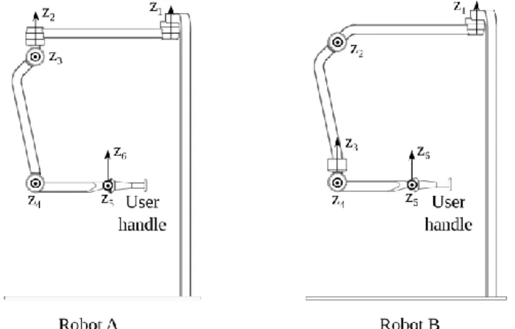
Robot description: The collaborative robot studied in this application is a simplified version of the strength
enhancement robot Cobot 7A.15 designed by RB3D and CEA-LIST (Fig. 1). The kinematic structure is a serial chain with 6 revolute joints. We compare two structures (A and B), which differ by the location and axes of two of the joints (Fig. 3).
Figure 3: Kinematic structure of robot A (left) and robot B (right).
In order to test the effect of a dynamic parameter on the DHM movement, the mass of the robot is varied. The original mass of each segment of the robot is scaled by the same parameter β. We compare 3 values for β: 0.6, 1.0 and 1.4.
The robot is controlled to provide strength enhancement: the robot joint torques are computed so that the force the robot exerts on the environment is an amplified image of the force applied by the worker onto the
robot. A user handle, located on the robot end-effector, is therefore equipped with a force sensor to measure the human-robot interaction force. In addition, the robot control law compensates the robot weight and the viscous friction effects. The inertial effects are not compensated. The full control law is:
𝝉𝒓 = 𝛼 𝐽𝑒𝑒,𝑟𝑇 𝑭𝒉+ 𝒈𝒓(𝒒𝒓) + 𝐵𝑟𝒒̇𝒓
where τr is the vector of robot joint torques, qr the vector of robot joint angles and q̇r the vector of joint velocities, gr the vector of gravity forces, Br the matrix of viscous friction coefficients, Jee,r the Jacobian matrix of the robot end effector, Fh the force applied by the DHM onto the robot end-effector, and α the amplification coefficient. Strength enhancement is provided only during the contact phase, i.e. on point P2.
During the free space phase, strength enhancement is not active (α = 0). We compare 4 values for α: 0, 1, 2 and 3. The theoretical value of the force the DHM needs to apply on the rigid body while in P2 is then: 80N
(α=0), 40N (α=1), 26.7N (α=2) and 20N (α=3).
DHM: The DHM used in this work is a rigid-body model consisting of 21 segments linked together by 20
joints, with a total of 45 degrees of freedom (DoFs). Each DoF is a revolute joint controlled by a single actuator (actuation variable: joint torque). Given a body size and mass, the model can be scaled according to average anthropometric coefficients to represent different morphologies.
The DHM motions are generated using the LQP controller presented in the previous section. A right hand acceleration task is created to follow the desired trajectory between P1 and P2 (straight line with a bell-shape
velocity profile). A right hand force task is activated while in P2 to exert the desired contact force. The feet
are immobile, i.e. there is no stepping or walking.
Data analysis: Two kinds of biomechanical quantities are measured on the DHM to evaluate the effects of
the robot: joint angles and joint torques. With the DHS, angles and torques can be measured for each DoF at each timestep of the simulation. In this study, however, only the joints of the right arm are analyzed since the robot is manipulated with the right hand. A position indicator and a torque indicator are defined to represent the stress on the whole arm during the whole simulation with a single value. The position indicator Iq is:
𝐼𝑞= 1 𝑁 ∑ ∫ ( 𝑞𝑖(𝑡) − 𝑞𝑖𝑛 𝑞𝑖𝑚𝑎𝑥− 𝑞𝑖𝑛) 2 𝑑𝑡 𝑇 0 𝑁 𝑖=1
and the torque indicator Iτ is:
𝐼𝜏= 1 𝑁 ∑ ∫ ( 𝜏𝑖(𝑡) 𝜏𝑖𝑚𝑎𝑥(𝑡)) 2 𝑑𝑡 𝑇 0 𝑁 𝑖=1
where N is the number of joints in the right arm (N=7), T is the duration of the simulation, qi(t) is the angle of
joint i at time t, and τi(t) is the torque of joint i at time t. qin, qimax and τimax are respectively the neutral position, joint limit and maximal torque capacity of joint i (neutral posture: standing arms along the body). In order to take fatigue into account, the torque capacity changes with time according to the model by Ma et al. (Ma, 2009): 𝜏𝑖𝑚𝑎𝑥(𝑡) = 𝜏𝑖𝑚𝑎𝑥(0) 𝑒−𝑘 ∫ 𝜏𝑖(𝑢) 𝜏𝑖𝑚𝑎𝑥(0) 𝑑𝑢 𝑡 0
where k is a fatigue rate assigned to 1min-1, and τimax
(0) is the nominal torque capacity of joint i.
Given the definition of both indicators, a higher value corresponds to higher stress. A detailed definition of the indicators is available in (Maurice, 2016).
Results
Tables 1, 2 and 3 present the effects of respectively the robot structure, mass and amplification coefficient on the position and torque indicators. The values presented in the tables are the percentages of increase or decrease compared to the condition without robot. Free space and contact phases are presented separately since prevailing physical phenomena and robot assistance differ in both phases.
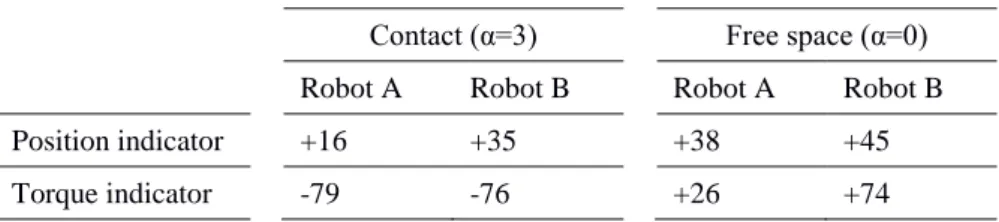
Contact (α=3) Free space (α=0) Robot A Robot B Robot A Robot B Position indicator +16 +35 +38 +45 Torque indicator -79 -76 +26 +74
Table 1: Percentage of increase/decrease in the position and torque indicators with robot A and robot B. The reference is the situation without robot. The robot mass is equal for both structures and is not varied (β = 1.0). In free space, no amplification is provided, while the amplification coefficient is set to α=3 for both robots during the contact phase.
Free space (α=0) Whole cycle (α=1) β = 0.6 β = 1.0 β = 1.4 β = 0.6 β = 1.0 β = 1.4 Position indicator +38 +38 +39
Torque indicator +13 +26 +48 -56 -54 -52
Table 2: Percentage of increase/decrease in the position and torque indicators for different masses of robot A. The reference is the situation without robot. During the contact phase, the amplification coefficient is set to α=1. Results of the contact phase are not displayed because the weight of the robot is fully compensated and there is no movement, so no inertial effects, during the contact phase. Therefore dynamic parameters of the robot have no influence.
Contact Whole cycle
α=0 α=1 α=2 α=3 α=0 α=1 α=2 α=3 Position indicator +17 +17 +16 +16
Torque indicator +6 -58 -72 -79 +7 -55 -67 -71 Table 3: Percentage of increase/decrease in the position and torque indicators for different amplification coefficients of robot A. The reference is the situation without robot. The robot mass is not varied (β = 1.0). Results of the free space phase are not displayed since the strength enhancement is not active in free space. Therefore the value α of has no influence.
Effect of the robot on effort: In free space, both robot A and robot B degrade the torque indicator (Table 1).
The additional effort required in free space when working with the robot is likely due to the robot inertia which is not compensated by the control law. Indeed, the torque demand in free space increases with the robot mass (Table 2). The increase in torque is much larger with robot B, because of the orientation of the joint axes with respect to the direction of the task. With robot A, joint 1 and 2 are not useful to move the end-effector from P1 to P2 (Fig. 3). Conversely, with robot B a motion of joint 2 is needed. One more segment
needs to be displaced, hence a higher inertia.
During the contact phase, both robots are equivalent regarding torque demand (Table 1). As expected, the torque indicator decreases when the robot provides more assistance (i.e. when α increases, Table 3). Nevertheless, the relation between the torque indicator and α is not inversely proportional, because fatigue is taken into account in the indicator calculation and modifies the joint torque capacity.
Despite the additional effort required to move the robot in free space, the effect of the robot on torque demand across the whole work cycle is beneficial; the positive effect of strength enhancement overtakes the negative effect of additional inertia. With α=1, the torque indicator is reduced by more than 50% (Table 2).
Effect of the robot on posture: Both robot A and robot B degrade the position indicator, in free space and
during the contact phase (Table 1). However the robot mass (Table 2) and amplification coefficient (Table 3) have no effect on the position indicator. Both these parameters affect the effort the DHM needs to produce (see values of the torque indicator). Therefore the change in posture is not due to a change in effort. Instead, the posture modification induced by the robot is likely due to collisions with the robot, which disrupt the DHM posture.
Discussion and Conclusion
The case-study presented above demonstrates that an LQP controller can be successfully used to animate a DHM interacting physically with a collaborative robot. Thanks to the dynamic simulation, the human-robot interaction is realistic: the robot control and the human posture both interactively adapt to the human-robot interaction force. The proposed animation technique therefore enables to quantity the biomechanical effects of kinematic, dynamic and control parameters of the robot on the human. If some phenomena could be anticipated in this simple case-study, quantifying their relative importance is not straightforward. Being able to quantify the relative ergonomic effects of different parameters is of great interest for the design of collaborative robots which often requires compromises.
Nevertheless, the reliability of the biomechanical quantities measured with the DHM depends on the realism of the DHM posture and motion. The dynamics-based animation technique generates movements that are more realistic than with purely kinematic techniques. Nevertheless, the DHM currently lacks autonomy regarding feet placement. Though the controller handles stepping and walking, the feet placement are entirely defined by the user and therefore not necessarily well-adapted to the task. Solutions for automatic online feet adaptation (Ibanez, 2014) and for optimal contact placement when significant external forces are at play (Liu, 2012) exist. However they are purely reactive whereas a human-being usually anticipates such movements. Anticipated optimal placement of contacts requires complex planning methods (Bouyarmane, 2011), which for now are computationally very expensive. More generally, simulating realistic human motions requires to understand the psychophysical principles that voluntary movements obey. The human motor control research community has established mathematical formulae for some of these principles, especially for reaching motions (Fitts’s law, minimum jerk principle,...). De Magistris et al. have successfully implemented some of them in their DHM controller (De Magistris, 2013). However, these improvements are currently limited because the driving principles are not yet known for all kinds of motions Despite these limitations, human-robot DHS is a promising tool for collaborative robot design. An example of application is presented in (Maurice, 2017), where we use the DHM controller described here to automatically optimize the design of a collaborative robot for a drilling task.
References
Schneider, E., Copsey, S., & Irastorza, X. (2010). OSH [Occupational Safety and Health] in Figures:
Work-related Musculoskeletal Disorders in the EU-Facts and Figures. Office for Official Publications of the
European Communities.
Parent-Thirion, A., Vermeylen, G., van Houten, G., Lyly-Yrjninen M., Biletta, I., & Cabrita, J.(2012). Fifth European working conditions survey, European foundation for the improvement of living and working conditions. Office for Official Publications of the European Communities.
US Department of Labor (2016). Nonfatal Occupational Injuries and Illnesses RequiringDays Away from
Work, 2015, Bureau of Labor Statistics, US Department of Labor.
Punnett, L., & Wegman, D. H. (2004). Work-related musculoskeletal disorders: the epidemiologic evidence and the debate. Journal of electromyography and kinesiology, 14(1), 13-23.
Krüger, J., Lien, T. K., & Verl, A. (2009). Cooperation of human and machines in assembly lines. CIRP
Annals-Manufacturing Technology, 58(2), 628-646.
Schmidtler, J., Knott, V., Hölzel, C., & Bengler, K. (2015). Human Centered Assistance Applications for the working environment of the future. Occupational Ergonomics, 12(3), 83-95.
Colgate, J. E., Peshkin, M., & Klostermeyer, S. H. (2003, October). Intelligent assist devices in industrial applications: a review. In Intelligent Robots and Systems, 2003.(IROS 2003). Proceedings. 2003 IEEE/RSJ
International Conference on (Vol. 3, pp. 2516-2521). IEEE.
Faber, M., Bützler, J., & Schlick, C. M. (2015). Human-robot cooperation in future production systems: analysis of requirements for designing an ergonomic work system. Procedia Manufacturing, 3, 510-517.
Li, G., & Buckle, P. (1999). Current techniques for assessing physical exposure to work-related musculoskeletal risks, with emphasis on posture-based methods. Ergonomics, 42(5), 674-695.
David, G. C. (2005). Ergonomic methods for assessing exposure to risk factors for work-related musculoskeletal disorders. Occupational medicine, 55(3), 190-199.
McAtamney, L., & Corlett, E. N. (1993). RULA: a survey method for the investigation of work-related upper limb disorders. Applied ergonomics, 24(2), 91-99.
Schaub, K., Caragnano, G., Britzke, B., & Bruder, R. (2013). The European assembly worksheet. Theoretical
Issues in Ergonomics Science, 14(6), 616-639.
Chaffin, D. B. (2007). Human motion simulation for vehicle and workplace design. Human Factors and
Ergonomics in Manufacturing & Service Industries, 17(5), 475-484.
Raschke, U. (2004). The Jack human simulation tool. Working postures and movements: tools for evaluation
and engineering. CRC Press, 431-437.
Seidl, A. (2004). The RAMSIS and ANTHROPOS Human Simulation Tools. Working postures and
movements: tools for evaluation and engineering. CRC Press, 454-462.
Fritzsche, L., Jendrusch, R., Leidholdt, W., Bauer, S., Jäckel, T., & Pirger, A. (2011). Introducing ema (Editor for Manual Work Activities)–A New Tool for Enhancing Accuracy and Efficiency of Human Simulations in Digital Production Planning. In International Conference on Digital Human Modeling (pp. 272-281). Springer, Berlin, Heidelberg.
Högberg, D., Hanson, L., Bohlin, R., & Carlson, J. S. (2016). Creating and shaping the DHM tool IMMA for ergonomic product and production design. International Journal of the Digital Human, 1(2), 132-152. Ruiz Castro, P., Mahdavian, N., Brolin, E., Högberg, D., & Hanson, L. (2017). IPS IMMA for designing human-robot collaboration workstations. In 5th International Digital Human Modeling Symposium,
Bonn/Germany, June 26-28, 2017.
Busch, F., Wischniewski, S., & Deuse, J. (2013). Application of a character animation SDK to design ergonomic human-robot-collaboration. In Proceedings of the 2nd International Symposium on Digital
Human Modeling (DHM).
Ore, F., Hanson, L., Delfs, N., & Wiktorsson, M. (2015). Human industrial robot collaboration-development and application of simulation software. International Journal of Human Factors Modelling and Simulation, 5(2), 164-185
Dombrowski, U., Stefanak, T., & Perret, J. (2017). Interactive Simulation of Human-robot Collaboration Using a Force Feedback Device. Procedia Manufacturing, 11, 124-131.
Delp, S. L., Anderson, F. C., Arnold, A. S., Loan, P., Habib, A., John, C. T., ... & Thelen, D. G. (2007). OpenSim: open-source software to create and analyze dynamic simulations of movement. IEEE transactions
on biomedical engineering, 54(11), 1940-1950.
Damsgaard, M., Rasmussen, J., Christensen, S. T., Surma, E., & De Zee, M. (2006). Analysis of musculoskeletal systems in the AnyBody Modeling System. Simulation Modelling Practice and Theory,
14(8), 1100-1111.
Salini, J., Padois, V., & Bidaud, P. (2011). Synthesis of complex humanoid whole-body behavior: a focus on sequencing and tasks transitions. In Robotics and Automation (ICRA), 2011 IEEE International Conference
Sentis, L., & Khatib, O. (2006, May). A whole-body control framework for humanoids operating in human environments. In Robotics and Automation, 2006. ICRA 2006. Proceedings 2006 IEEE International
Conference on (pp. 2641-2648). IEEE.
Escande, A., Mansard, N., & Wieber, P. B. (2014). Hierarchical quadratic programming: Fast online humanoid-robot motion generation. The International Journal of Robotics Research, 33(7), 1006-1028. Abe, Y., Da Silva, M., & Popović, J. (2007). Multiobjective control with frictional contacts. In Proceedings
of the 2007 ACM SIGGRAPH/Eurographics symposium on Computer animation (pp. 249-258). Eurographics
Association.
Kanoun, O., Lamiraux, F., Wieber, P. B., Kanehiro, F., Yoshida, E., & Laumond, J. P. (2009). Prioritizing linear equality and inequality systems: application to local motion planning for redundant robots. In ICRA
2009-IEEE International Conference on Robotics & Automation (pp. 2939-2944). IEEE.
De Magistris, G., Micaelli, A., Evrard, P., Andriot, C., Savin, J., Gaudez, C., & Marsot, J. (2013). Dynamic control of DHM for ergonomic assessments. International Journal of Industrial Ergonomics, 43(2), 170-180. Kajita, S., Kanehiro, F., Kaneko, K., Fujiwara, K., Harada, K., Yokoi, K., & Hirukawa, H. (2003). Biped walking pattern generation by using preview control of zero-moment point. In ICRA (Vol. 3, pp. 1620-1626). Merlhiot, X., Garrec, J. L., Saupin, G., & Andriot, C. (2012). The xde mechanical kernel: Efficient and robust simulation of multibody dynamics with intermittent nonsmooth contacts. In The 2nd Joint
International Conference on Multibody System Dynamics.
Ma, L., Zhang, W., Chablat, D., Bennis, F., & Guillaume, F. (2009). Multi-objective optimisation method for posture prediction and analysis with consideration of fatigue effect and its application case. Computers &
Industrial Engineering, 57(4), 1235-1246.
Maurice, P., Padois, V., Measson, Y., & Bidaud, P. (2016). Experimental assessment of the quality of ergonomic indicators for dynamic systems computed using a digital human model. International Journal of
Human Factors Modelling and Simulation, 5(3), 190-209.
Ibanez, A., Bidaud, P., & Padois, V. (2014). Emergence of humanoid walking behaviors from mixed-integer model predictive control. In Intelligent Robots and Systems (IROS 2014), 2014 IEEE/RSJ International
Conference on (pp. 4014-4021). IEEE.
Liu, M., Micaelli, A., Evrard, P., & Escande, A. (2012). Task-driven posture optimization for virtual characters. In Proceedings of the 11th ACM SIGGRAPH/Eurographics conference on Computer Animation (pp. 155-164). Eurographics Association.
Bouyarmane, K., & Kheddar, A. (2011). Multi-contact stances planning for multiple agents. In ICRA'2011:
International Conference on Robotics and Automation (pp. 5246-5253). IEEE.
Maurice, P., Padois, V., Measson, Y., & Bidaud, P. (2017). Human-oriented design of collaborative robots.