Aquadio: Wearable Product Development
by
Ryan Gulland and Travis Libsack
Submitted to the
Department of Mechanical Engineering
in Partial Fulfillment of the Requirements for the Degree of Bachelor of Science in Mechanical Engineering
at the
Massachusetts Institute of Technology
June 2018
0 2018 Massachusetts Institute of Technology. All rights reserved.
Signature redacted
Signature of Author: Signature of Author: Department /Signature redacted
of Mechanical Engineering May 24, 2018Depart ent of Mechan1 al Engineering
/7 x-? /May 24, 2018
Certified by:
Signature redacted
Signature
David Wallace
redacted
Professor of Mechanical EngineeringThesis Supervisor
MASSACHUSETTS INSTITUTE OF TECHNOLOGY
Rohit Karnik Associate Professor of Mechanical Engineering Undergraduate Officer Accepted by:
Aquadio: Wearable Product Development
by
Ryan Gulland and Travis Libsack
Submitted to the Department of Mechanical Engineering on May 24, 2018 in Partial Fulfillment of the
Requirements for the Degree of
Bachelor of Science in Mechanical Engineering
ABSTRACT
Aquadio was a product design project started by a group former 2.009 students who wanted to continue learning through doing - we were interested in running our own learning experience by designing our own product. The team was organized like a start-up, using a top-down
organizational structure and breaking up our team into a number of sub-teams. We started with an idea following a nominal product development process, were able to research and interview enough users to convince ourselves and others that our idea was feasible and useful. Throughout the project we honed our electrical, mechanical, software, and integration skills as a team. The product, called Aquadio, was device designed to help competitive swim teams train smarter by providing real time information and feedback to coaches and swimmers. By the end of the term we had successfully been through two iterations of our product. This work documents these design iterations and what was learned about industrial design, printed circuit board design,
software user interface design, and integrating all three of these aspects. Further, through the course of the project, we justified our design decisions with responses from real world users. Finally the thesis reflects on the process that was followed. Overall, the design process we used throughout the semester was successful. The hardware challenge of creating a wearable was successfully executed - we were able to match the size constraints swimmers needed with our electronics and mechanical components. However, it was realized that electrical and mechanical design should have been more tightly coupled, and a stronger focus placed on industrial design at the earlier stages of the project. Additionally we underestimated the importance and the amount of time required to integrate all device systems for a working alpha prototype.
Thesis Supervisor: David Wallace
Acknowledgements
We would like to first thank our team members:
Stephen Gaffley, Tristan Honscheid, Kevin Palisoc, Fernando Sanchez, Mingshi Wang, Karen Fan, Annie Dai, Andreea Martin, Aaron Lytle, and Aaron Wubshet. Working together this semester has been both fun and rewarding. Our experiences as a team were more valuable due to the diversity brought by our wide range of majors and skillsets. We had a great semester and would work with this team again in a heartbeat!
We would also like to thank Professor Wallace for meeting with us every week and being the first to give feedback on our progress. We also would like to thank him for inspiring our semester - without 2.009 we would have never started work on Aquadio.
We want to acknowledge Josh Ramos and the rest of the CAD Lab for helping us at every corner prototyping in the PDL. We couldn't have made the prototypes we did without their essential advice and guidance.
Finally we would like to thank the countless swimmers and coaches we talked to over the course of the semester. They're the reason we continued with this project in the first place and were critical in helping us develop our ideas.
Table of Contents Abstract 2 Acknowledgements 3 Table of Contents 4 List of Figures 6 List of Tables 7 1. Introduction 8 1.1 Team Introduction 8 1.2 Product Introduction 9 1.3 Aquadio Architecture 10 1.4 Team Organization 13 2. Mechanical Subsystem 14 2.1 Team Makeup 14
2.2 Timeline and Goals 14
2.3 Ship Form Industrial Design 15
2.3.1 Device Head Placement 15
2.3.2 Swimmer Interviews 16
2.3.3 Industrial Design 18
2.4 Dock Industrial Design 22
2.5 Electromechanical Integration 23
2.6 Fabrication and Design Process 28
2.7 Conclusion 29
3. Electrical Subsystem 31
3.1 Team Makeup 31
3.2 Timeline and Goals 31
3.3 Revision 1.0 32
3.3.1 Ship Architecture 33
3.3.2 Dock Architecture 36
3.3.3 Component Selection 36
3.3.4 Layout and Assembly 37
3.4.1 Ship Layout 39
3.4.2 Ship Assembly 40
3.4.3 Dock Layout and Assembly 41
3.5 Conclusion 42
4. Software Subsystem 44
4.1 Team Makeup 44
4.2 Timeline and Goals 44
4.3 Conclusion 47
5. Conclusion 48
5.1 Summary 48
5.2 Future Improvements 48
List of Figures
Figure 1-1: Aquadio Team Photo in Killian Court 8
Figure 1-2: Final Visual Model 9
Figure 1-3: Aquadio Product Lineup 10
Figure 1-4: Swim Practice Storyboard 11
Figure 2-1: Candidate Locations for Bone Conducting Audio 15
Figure 2-2: Mood Board 17
Figure 2-3: Color Swatches 18
Figure 2-4: Mid Semester Form Factor Concepts 19
Figure 2-5: Second Round Industrial Designs 20
Figure 2-6: Final Ship Form Factor 21
Figure 2-7: Ship Housing Front and Back 22
Figure 2-8: Dock Industrial Design Concepts 23
Figure 2-9: Final Dock Housing 23
Figure 2-10: Ship Mechanical Integration CAD 25
Figure 2-11: Assembled Ship Electronics 27
Figure 2-12: Swimmer - Aquadio Interaction 28
Figure 2-13: Ship Concept Evolution 29
Figure 3-1: Early System Architecture Diagram 32
Figure 3-2: System Circuit Board Architecture 33
Figure 3-3: Schematic of 1.0 Development Radio Networks 34
Figure 3-4: Schematic of 1.0 Development Power Circuitry 35
Figure 3-5: Microprocessor Pinout as shown in Configuration Utility 36
Figure 3-6: Ship PCB Version 1.0 38
Figure 3-7: Sensitive Electronics Layout 39
Figure 3-8: Unpopulated and Populated 2.0 Ship PCBs 40
Figure 3-9: Populated and Unpopulated 2.0 Dock PCBs 41
Figure 3-10: Ship Printed Circuit Board Evolution 42
Figure 4-1: Backend Data Structure 44
List of Tables
TABLE 1-1: TABLE 2-1:
Product Contract
Audio Placement Location Testing Results
12 16
1. Introduction
1.1 Team Introduction
The Aquadio project started in the Spring Semester as a group of 12 students who were looking to organize and execute their own design project. Most of our team had previously been in 2.009 (Wallace), a senior capstone design class, and enjoyed working in a large team developing a product prototype from an original idea. This semester we decided to diversify our team, bringing in talent from other majors; giving us the
technical breadth to pursue a fully integrated product with heavy electronic and software components.
The 2.009 class is focused around a team of 18 undergraduates who go through the process of ideating and designing a full alpha prototype of a product to be presented at the end of the semester. We appreciated the framework that 2.009 provided, allowing us to learn more about engineering and student leadership. We also benefited by being given the autonomy to develop a sense of ownership and make our own mistakes while being given the support necessary to succeed. Working off of our positive experience in 2.009 we formed a team to take one of our early ideas, Aquadio, and continue to try and develop it during the Spring Semester.
1.2 Product Introduction
During 2.009, Aquadio was proposed as a tool to provide real time information on swimming statistics to swimmers and coaches. We saw that swimmers lacked personal fitness devices, similar to ones that runners or bikers might have. Additionally, coaches lacked critical training information on the current performance of their swimmers due to the difficulties involved in manually capturing it. To fill this need we planned to design a wearable electronic device for swimmers to be worn while in team practice. Continuing the project in the spring, we were confident in the problem we were trying to solve due to our research in 2.009, but knew we needed more specificity regarding the exact user needs of the coach and swimmer. Using the first part of the semester we reached out to a number of different coaches and swimmers and asked them about what they wanted to see in a new tool for competitive swim teams. From these interviews we came up with a better understanding of our product concept that we used going forward to inform our design decisions.
Aquadio's new product vision is a system for competitive swim teams to help better collect and understand practice data. Unlike other cardio sports, like running and biking, swimming is lacking both quality information and communication while
practicing - both of which are critical to improving the ability of athletes. Aquadio helps solve both of these problems. Our device collects data during each swimming set, stores it and displays it for both coaches and swimmers. While swimming, Aquadio is also able to provide swimmers both automated data readouts, like lap time, and play pre-recorded audio sound bites provided by coaches, such as instructions to watch their turns.
1.3 Aquadio Architecture
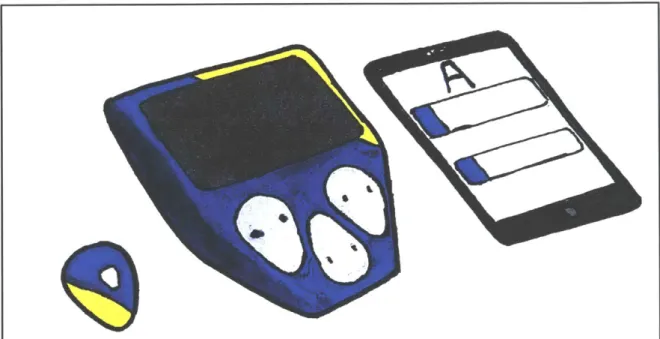
The architecture of Aquadio is broken up into three main components: the ship, the dock, and the online coach interface.
Figure 1-3: Aquadio Product Lineup. From left to right: "Ship Device", "Dock Device", and coach
tablet with the coach's user interface.
The ship device is worn by swimmers. It is the core of our product and is capable of collecting information from swimmers, speaking directly to swimmers, and relaying that information back to the poolside. For the poolside we developed a device called the dock. The dock acts as a charging station for the individual ship units and also uploads
swimmers' data to the cloud. While practicing, the coach will be able to view swimmers' splits and other swimming data on a tablet device by accessing the cloud database, getting feedback in real time. Likewise, when swimmers are done with practice they will be provided an interface for their personal practice data.
dd
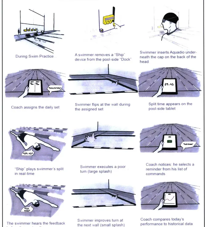
During Swim Practice A swimmer removes a "Ship" device from the pool-side "Dock"
Swimmer inserts Aquadio under-neath the cap on the back of the
head
24-4
NE-7 M~
Coach assigns the daily set
Ship plays swimmer's split in real-time
The swimmer hears the feedback
before the next wall
Swimmer flips at the wall during
the assigned set
Swimmer executes a poor
turn (large splash)
Swimmer improves turn at
the next wall (small splash)
Split time appears on the pool-side tablet
Coach notices he selects a reminder from his list of commands
Coach compares today's
performance to historical data
I
Figure 1-4: Storyboard. Walkthrough of how Aquadio might be used in swim practice.
As a tool used by swimmers and coaches it was critical for us to design a product that would fit into the current practice structure. Designing a new pool full of sensors is impractical and costly. Instead we decided to focus on developing a small device that
swimmers could wear without having to interrupt their training routines. Coaches also
'T"K"noW
"24
need something that could easily integrate into their training styles and be used effectively to coach. These goals led to our design choices throughout the semester.
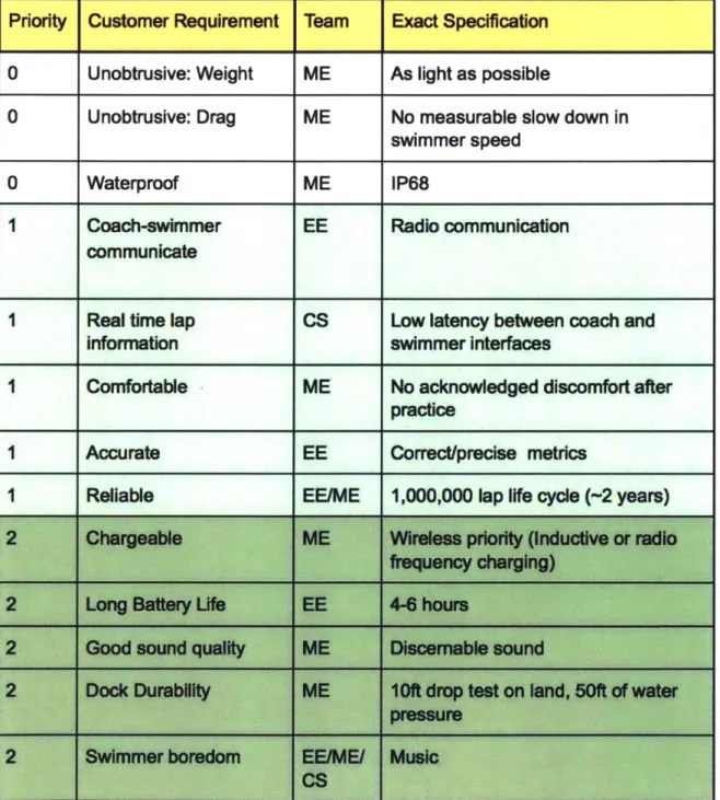
Priority Customer Requirement Team Exact Specification 0 Unobtrusive: Weight ME As light as possible
0 Unobtrusive: Drag ME No measurable slow down in
swimmer speed
0 Waterproof ME IP68
1 Coach-swimmer EE Radio communication
communicate
1 Real time lap CS Low latency between coach and
information swimmer interfaces
I Comfortable ME No acknowledged discomfort after
practice
I Accurate EE Correct/precise metrics
I Reliable EE/ME 1,000,000 lap life cycle (-2 years)
2 Chargeable ME Wireless priority (Inductive or radio
frequency charging)
2 Long Battery I-fe EE 4-6 hours
2 Good sound quality ME Discemable sound
2 Dock Durability ME 10lft drop test on land, 50ft of water pressure
2 Swimmer boredom EE/ME/ Music
CS
Table 1-1: Product Contract describes all product requirements and ranks them on a scale of 0 (most
1.4 Team Organization
To coordinate a 12-person team for a semester project we decided it would be expedient to elect a leadership structure to ensure good communication and
accountability throughout the term. We elected two team leads and a financial officer to oversee the team's organization and finances respectively.
Additionally, networks were put in place to assist in providing outside review and experience. We compiled a list of industry professionals, researchers, and professors who would act as technical and business reviewers and mentors. Furthermore, a list of
swimmers, coaches, and other users would act as a source of user feedback. The team was able to procure three sources of funding during the first month that managed to satisfy our budgetary estimates for the term: MIT CADLAB, Sandbox, and ProjX would fund development of our project.
The team divided into three core technical sub-teams: mechanical, electrical engineering & firmware, and computer science & user interface; each with their own sub-team lead and rosters. Our mechanical sub-team consisted of five members and was tasked with following through on an integrated mechanical housing design to be carried from early user testing, through industrial design, to a final alpha prototype. Our electronics and firmware team of four was tasked with creating functional supporting electrical hardware to enable a final integrated demonstration of core features. The computer
science and user interface team of two was tasked with designing the user experience of the coach's interface along with all necessary backend to support communication
between the dock device and cloud data services. Subsets of the electrical and mechanical team were also tasked with working on Aquadio's product vision and business plan during the early part of the semester. These early interviewing and research tasks held solidify our general project scope that aided in technical development.
2. Mechanical Subsystem
Team Members: Travis Libsack, Kevin Palisoc, Annie Dai, Aaron Lytle, Stephen Gaffley 2.1 Team Makeup
The mechanical team was given the task of designing the mechanical housings and user interactions for both the ship and the dock. The most important task for our team was to make the ship easy to use for swimmers. The first questions we sought out to answer were focused on how swimmers would wear the device and how Aquadio would fit into their everyday practices. Secondly, we wanted to be able to design a dock that matched the form factor of the ship and seamlessly integrated into teams' practices. We worked closely with the electronics team in designing a housing that fit all of their electronics in a functional way.
Our team was made up of five mechanical engineers previously enrolled in 2.009. Each of us has a technical background in mechanical engineering with strong focus on product development and rapid prototyping. Using the knowledge from our previous work together we were able to continue into the spring semester knowing each of our
strengths and weaknesses and we were confident in our ability to work off of those. 2.2 Timeline and Goals
Our timeline for the semester was heavily influenced by our two major goals: the industrial design of the ship and the housing for the electronics. Therefore we broke our semester up into two sections: a presentation for the first half of the semester and a final presentation at the end of the term. These deadlines made it easy for us to subdivide our work. For the first part of the term we wanted to focus heavily on swimmer interviews
and industrial design. For the second part of the term we wanted to focus solely on electrical-mechanical integration to make sure we had a working prototype by the end of the semester.
A majority of the mechanical design for Aquadio was the industrial design of the ship and dock. These took priority over the other engineering aspects because they are the most critical in making our product usable for swimmers. In order to integrate Aquadio
seamlessly into practices we needed to ensure that the forms were intuitive and easy to use. The ship took priority and we iterated multiple times in order to arrive at our final
2.3 Ship Industrial Design 2.3.1 Device Head Placement
Before deciding on the form of the ship we needed to find locations a swimmer could wear the device. We started out by brainstorming different locations where we could get the accelerometer data we needed and the audio quality we desired. This left us with one feasible option, the head. We started out by testing audio quality on different
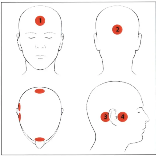
locations of the head outside of the water. Using a type of audio driver that was designed to vibrate bones in the head, also known as a bone conduction speaker, we picked four different boney locations to test. Two of them were standard locations for bone
conducting headphones - behind and in front of the ear. These locations are close to the ear canal and transfer vibrations well to your inner ear. The other two locations were unique - on the forehead and the rear base of the skull.
Figure 2-1: Candidate locations for bone conducting hardware. The mechanical team tested these in the
pool to pick the best option. Position 1 is on the forehead, position 2 is on the back of the head, position 3 is behind the ear, and position 4 is in front of the ear.
1
2
With these locations in mind we went to the pool to test the speaker in these four different positions. We were looking for quality audio, comfort, and discrete placement.
Forehead (1) Back of Head (2) Back of Ear (3) Front of Ear (4)
Audio Quality in - + + Air Audio Quality in + + + + Water Location Comfort + + + -Discrete - + - -Placement*
Table 2-1: Audio Placement Location Testing Results. The mechanical team went to the z-center and
tested the bone conductor in a number of different locations and ranked them based on different criteria.
Interestingly, from the chart above, the audio quality increased once the skull was partially or fully submerged in water. Initially it was hard to hear audio from Locations 1 and 2, but once we started swimming the audio was extremely clear. This unexpected difference in audio quality in and out of the water was perfect for us - swimmers could easily ignore audio when stopped, but just as easily hear it while swimming.
Next we rated the comfort and discrete placement of each location. The more sensitive parts of the head received a lower rating (soft spot in front of the ear), while the harder/bonier locations received a better rating. The discrete placement rating was based on how natural the location felt. The worst location was on the forehead, which was expected, and the best was on the back of the head, which blended in naturally under a swim cap.
Our conclusions from this round of testing were to make form factors to be worn on the back of the head. This also worked out well when talking to the electronics team about integration: it was one of the only spots we would be able to fit all of their electronics comfortably.
2.3.2 Swimmer Interviews
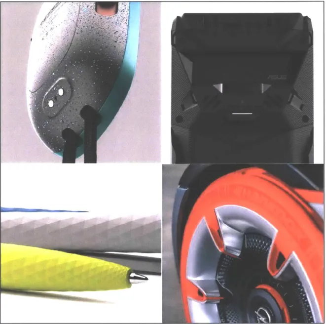
The next step in our industrial design process was to interview swimmers and ask their opinions on colors, form, and head location. We interviewed over five college and post-collegiate swimmers from MIT, Holy Cross, RIT, and New Jersey. The mood board we designed helped us decide on the color scheme of the device and the types of curves
and edges swimmers liked seeing. From the mood board we came up with a few different color schemes that included some bright, saturated, athletic colors, along with some dark black and blue tones.
4 ~ A Jt~? ~mimh
I
u
Figure 2-2: Mood Board. Images that interviewed swimmers liked best. They include soft and hard edges
as well as bright, athletic colors.
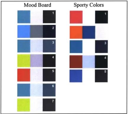
We also learned that swimmers wanted a mix of hard and soft edges. The hard edges helped emphasize some natural competitiveness while the soft edges appeared more hydrodynamic and comfortable. Swimmers also said they liked the idea of a non-symmetric geometry or color pattern if the device was visible during practice.
Mood Board Sporty Colors
Figure 2-3: Color Swatches. Color combinations from the mood board and sporty color combinations compiled from other known products.
When we finally asked the swimmers about head locations, all of them not only mentioned wanting to wear a device like this on the back of their heads, but also
mentioned putting it under their cap. This was not something we were expecting both men and women to say and changed how we viewed designing a device for swimmers to wear.
2.3.3 Industrial Design
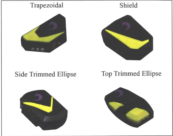
By our technical review halfway through the term, as explained above, we had completed the first round of industrial design and walked away with four different devices to test with swimmers. Each of the devices had a unique shape and followed the three factors above: color, pattern, and location. However, each of these devices also came with a strap for testing which, through more interviews, we found unnecessary.
Trapezoidal
Side Trimmed Ellipse
Top Trimmed Ellipse
Figure 2-4: Mid-Semester Form Factor Concepts. We iterated on four different industrial design styles for
our mid-semester presentation. Each is above with a unique name we used to identify them.
Over the next couple of weeks we showed swimmers these models, but nobody was really impressed with their design. Not only were their forms uninspiring, but they were too large. With new size information from the electronics team we were able to
create a control volume and decided to create a large number of new forms based on those. We picked three forms from our previous iterations and interviews with swimmers to re-sketch and re-model using foam. The three models we chose to use were: side-trimmed ellipse, top-side-trimmed ellipse, and shield.
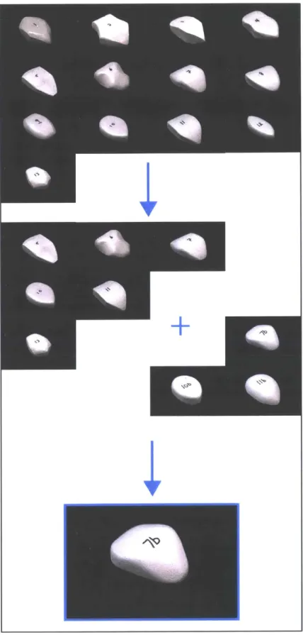
Figure 2-5: Second Round of Industrial Design. On this iteration
of industrial design we went to swimmers directly to see which form factors they liked better. Swimmers ended up liking model
We went to the pool with our new foam models and tested out each of them on ourselves to pick our favorite ones. During our testing we were watching two different factors: ease of application and comfort. Based on our findings we made three new models that we then tested with swimmers. From our user testing with swimmers we were able to come away with a top favorite model, 7b, which is what we used for our final form.
We then used the 7b model to take photos and transfer to a 3D model that we could use to manufacture our final integrated device.
Figure 2-6: Final Ship Form Factor. We transferred the 7b foam model into CAD.
Finally, after creating the 3D model, we used a 3D printer to get a physical copy of our design. Using some finishing techniques, which we will go into more detail about later on, we ended up with the final form factor and color of our ship.
Figure 2-7: Ship Housing Front and Back. The final color and form of the ship device. 2.4 Dock Industrial Design
The industrial design of the dock followed a similar process to that of the ship, although it took a backseat. Using what we learned about the design of the ship we sketched out ideas for a charging and pairing station, what we called the dock, to be wall-mounted on the pool deck. The requirements for the dock included housing the ship charging electronics and a large screen used for pairing ships with swimmers. To test out different dock forms we first sketched and then modeled them out of foam. After
presenting them to our team we narrowed down our focus to design a final dock with parts from a few of the designs above. Our final dock was to include charging pads on the front face of the device, to make removing the ships easy, and also allow a narrow form factor, to make it non-intrusive on the pool deck. We also decided to match the form and color to the ships in order to have a complete form language in our design.
Face Mount Register
Pocket Mount
Space Ship
Figure 2-8: Dock Industrial Design Concepts. These were the first four concept models we created for the
dock. For our final prototype we implemented concepts found in each design.
The final dock was a foam and 3d printed model used to show the functionality of the docking function and give an idea of its size.
Figure 2-9: Final Dock Housing. Using the aesthetics from the ship and the insight from the dock
2.5 Electromechanical Integration
The electromechanical integration was a critical aspect of our product. Because a large factor of our industrial design was the size and fit of the device, fitting electronics in a small package was important to our product. We had designed our second round of form factors (shown above) around a control volume discussed with the electronics team, making the final integration much easier.
After designing around the control volume we needed to position different components of the ship that were critical to the design. These included: a battery, a bone conducting speaker, charging pogo pins, an antenna slot, an input button, and an LED
indicator. Based on our industrial design and user interviews we had a few requirements for the electronics layout; specifically we cared about the printed circuit board (PCB) aspect ratio, overall part thickness, speaker placement, and charging pin placement. Out
of these we prioritized the aspect ratio of the PCB and the overall thickness of the
electronic components. Through discussions with the electronics team we came up with a component layout that satisfied the requirements of the 7b design.
3m:
Figure 2-10: Ship Mechanical Integration CAD. Above is the layout of the internals of the ship in
SolidWorks. In no specific order: bone conducting speaker, battery, PCB, charging pins, , U
LED, antenna, and magnets.
Our first, and most important, consideration in laying out the inside of the ship was the PCB placement. The PCB has important charging pins, LEDs, and buttons that the mechanical team needed to interface with. The PCB also had sensitive electronics that needed to be further away from higher power devices, like the bone conducting speaker. The layout we chose to use involved stacking the battery and PCB on top of each other
and placing them below the bone conduction speaker. We then created a gap in the PCB to fit the speaker and place the charging pins as far forward as we could get them.
Our next consideration was the antenna. Based on the needs of the electronics team we decided to use a 1/4 wavelength antenna and wrap it around the housing of the device. We tried to keep it as straight as possible while keeping it out of the way of other components.
Finally, we added magnets to aid in docking and charging. We put these as far forward as we could in order to not interfere with our radio. We also placed them close to the charging pins in order to make sure charging was more reliable.
The user interface we included in the ship was in the form of a button and an indicator LED. Both the button and the LED needed to be on the front of the device to make use and assembly easier. More specifically, the button interface was made out of a rubbery material, which was hard to press, and placed in the center of the device, which made it easy to find. The included LED was important for checking charging and power status and was placed in the front of the device below the button.
Figure 2-11: Assembled Ship Electronics. An assembled ship is above with most of the internal electronics
mentioned in the version of assembled CAD. In no specific order: bone conducting speaker, PCB, charging
pins, , UI LED, antenna, and magnets.
Even with a relatively small form factor, we still had a lot of unused space in our model which will be useful during further development. However, at this stage, our model was successful in fitting the electronics while also matching the form factor wanted by users.
Dock integration was low priority due to the time constraint of the project. We didn't get to finish an entire housing, but instead designed the charging ports of the dock
AWN",
A
/A
and created a foam model around another control volume based on the dock electronics. The most critical aspect of the dock is the charging ports because they are the part that swimmers need to interact with on the pool deck. We also made sure to include a large screen on the dock. Similar to our previous foam models this screen would be used for swimmers to pair with ships before getting into the pool.
Figure 2-12: Swimmer Aquadio Interaction. Above a swimmer is removing one of the ships from a dock charging port.
2.6 Fabrication and Design Process
The fabrication method for different parts of our project varied over the semester depending on the stage of our design. All of our designs started on paper and were then made out of dense foam. Once a design was favored we iterated and then transferred the model to a CAD program, like SolidWorks. Finally, we 3D printed our final parts or molds for final parts. 3D printing was the method of choice because it was quick and we were able to get most of the geometries we wanted without having to spend hours machining our housings.
b~~i
Figure 2-13: Ship Concept Evolution. Above shows the process of sketching, foam modeling, CAD
modeling, and finally finishing a part. This is a process we used and repeated many times throughout Aquadio.
A large part of our prototyping was also finishing - in order to make our foam and final models look professional we needed to spend time painting and finishing parts. This is something that is critical to presenting our ideas to others and is also something that can get easily overlooked. For our models we used basic finishing techniques for 3D printed parts, using spray paint and filler to get the finishes we were looking for.
In the future the design for the ship would be entirely injection molded with the possibility of using over-molded rubber. Finishing would be done with different colored plastics and mold finishes. Different plastics would also allow us to create a drop-resistant device within the constraints of our form factor.
2.7 Conclusion
The mechanical design mainly focused on the industrial design of Aquadio and how it shaped the user experience of our device. Through swimmer interviews and model making we were able to narrow down our design to something we were confident
swimmers would like. After this was decided, we shifted our primary focus to working closer with the electronics team to create an integrated device.
This process worked well, but at times had its pitfalls. For example, needing to wait on the electronics team before creating a final housing design was a struggle - it
/
~ -~
caused the mechanical team a major schedule slip and extended the overall length of the project.
Another important lesson came from industrial design process. Our first four models were primarily influenced by drawings and of what we liked best. We had failed to bring physical models to swimmers and test them in the pool. The second round of industrial design was done much better and was able to teach us the correct way to go about designing a product for a user group. If this project were repeated we would have dedicated the first half entirely to industrial design and the second half entirely to electronics integration.
Despite our work over the semester there are a number of things we hope to improve in future iterations of the product. The housing as it stands is good enough to act as a test bed for the firmware, however in the future we could work on optimizing the space usage in the device. We would also prioritize the style of user input and feedback, which are currently underdeveloped and place-held by a single button and led. Future work would also focus on testing the drop resistance of the housing and adding softer materials to make it more comfortable to wear for long periods of time in the pool.
3. Electrical Subsystem
Team members: Andreea Martin, Ryan Gulland, Tristan Honscheid, Aaron Wubshet, Fern Sanchez
3.1 Team Makeup
Our team consisted of four members: one mechanical engineer with past 2.009 electronics experience, three electrical engineers separately specializing in PCB design, firmware development, and radio system engineering, and a computer scientist
specializing in data processing. These diverse skill sets allowed us to tackle the variety of challenges faced throughout the course of the project. Additionally, having members specializing in mechanical engineering and firmware design allowed for natural points of contact for integration with the mechanical and software sub-teams respectively.
3.2 Timelines and Goals
The electrical engineering and firmware sub-team was first tasked with ensuring the technical feasibility of the project. Second, our sub-team was responsible for creating functional electronics with the end goal of a fully-featured end of semester electronics demo.
The level of technical complexity inherent in this project and the expected size and power constraints involved with creating a wearable device necessitated
implementing a variety of technologies. First, the compact, highly customized nature of the ship unit needed a PCB to hold a wide range of integrated circuits in a very compact form factor. We also decided to design a PCB for the dock to reduce bulk and keep the layouts and programming as similar as possible to the ship. Our end of term goal would therefore be to create functioning PCBs demonstrating full functionality in the final form factor.
In order to accomplish this we split our semester based on our two large
deliverable dates: technical review halfway through the semester and a final presentation at the end of the term. For technical review we wanted concrete proof of technical
feasibility and feedback on the technical aspects of the project. We therefore set a goal of making large, redundant development boards to demonstrate full functionality of the different electrical subsystems of the final product. For the end of term presentation we decided to make the smallest, fully featured, optimized, and electromechanically
integrated boards possible based on the same architecture as the development boards. This would enable the aforementioned fully functioning alpha prototype when paired with some minor electromechanical integration.
3.3 Revision 1.0
The first set of development boards were designed with the intent of maximizing ease of development, redundancy, and reparability while including all potential systems for each final board. We chose to go directly into making development boards instead of breadboard prototyping both to save money and because all of our critical risks were in size, power, and radio communication, which could not be sufficiently simulated in a bread-boarded format using off the shelf components. Additionally, we knew a device architecture like this could be accomplished using breadboard components from our experiences in 2.009 and didn't feel a need to recreate those trials.
Cloud Database
Surfaced
0
RX, TXpo
Submerged
QnQ
"Ships"
"Dock"
"Coach"
Wearable Device on Swimmer Poolside Station BPuersoal Tablet
Bluetooth . Radio a Wi-Fi
Figure 3-1: Early System Architecture Diagram. This diagram shows the connectivity between the various
electronic devices in Aquadio.
The small, wearable ship boards must be capable of collecting data, storing it, and playing it back as audio. Additionally, the ship and dock must communicate wirelessly over radio, allowing ships to send swimming statistics and metadata to the dock. The dock must be capable of collecting transmissions from the ships, broadcasting small commands, such as the current workout, charging ships while docked, and uploading all processed statistics to a cloud database. Originally, a low latency Bluetooth connection would allow push to talk communication without requiring a complicated app on the
coach tablet or computer, however the feature was not prioritized and later removed.
Finally, the coach is able to access the cloud database, viewing real time statistics on any connected device.
Volume / power buttons Indicator LEDS 12 Bit LP DAC -Audi Bone AMP -o Exciter Conductor Lipo b internal serial port 6-9 DOF IMU STM32 MCU
Voltage - ISM Trancelver Regulator
RF Antenna
PM-C Upo - Gas Gauge
Charging Pins Indcaor LEDS Receive Antenna ISM Tranclever Power Amplifier ____ Transmit Antenna I I
Charging Pins - USB
Raspi
KScreen
ButtonsCloud
5V Power Bus (conn all)
Regultor - 29V In Charger
Figure 3-2: System Circuit Board Architecture.
3.3.1 Ship Architecture
Based on this architecture, the ship necessarily consisted of six major subsystems: user interface, audio, sensing, radio, power, and microcontroller. The first of these, the user interface, simply consisted of buttons and LEDs at this point due to lack of user
interview specificity.
Second, the audio system needs to be capable of driving the 4-8 ohm bone conduction speakers we were testing at over a Watt of peak power draw. We chose to include a separate external digital analog converter redundant with our selected amplifier's internal one for redundancy and programming options.
From our testing the prior semester we estimated that the sensing system needed to comprise of only one 6 degree of freedom inertial measurement unit capable of reading linear and angular accelerations in all three axis in order to successfully detect strokes.
I03"--.- C '--M - GM a s$ 557515 ~ WX AM91 .M VDDU WO MIQMIU 2, 64D hoUN Gi
Figure 3-3: Schematic of 1.0 Development Radio Networks. In no specific order: Texas Instruments radio,
power supply, Texas Instruments matching network (radio), Silicon Labs radio, Silicon I abs matchinc
lw ork (radio).
The radio system, which was identical across both devices, was easily the most complicated and highest risk, as we expected to have difficulty with both population of the dense radio matching networks and designing the necessary radio protocol drivers. Therefore, we chose to make two separate, redundant radio systems using different chipsets in case we encountered unforeseen difficulties with either system. Power to the two devices was isolated via a jumper to easily switch between devices. The matching networks of the devices were selected for 440Mhz operation, a useful frequency for both underwater and air operation.
L19 WO-GUARD RFAETN ak ... 2" WC 7 SO(GOWI) cow., Opew GPM DM DCPL-VCO DcrL-PM-CH? N
T
47.F W B-A, W -T-L M_ Z0 19 GiD RZI SW2 47,F GM I XOW-42 31 XF Z*3C LM law GiD LXkX7
$4 V9SM
CAM" am Cl) CY, GM (LIM ]us C74 Mr n MY Cl-u 11 1 C53- FOA-1-211J.10"MMID I Eo8i* tk 4 T it -- C46-1 1 - C.4 DU I U
Wireless Power
D, -: to=_
-am Tcam
Figure 3-4: Schematic of 1.0 Power Development Circuitry. In no specific order: USB interface, wireless
power (deprecated), battery management system, po ci m itch, voltage regulators, gas gauge.
The power system is decidedly more complicated than our other modules: it consists of a battery power-management circuit, a gas gauge, multiple low dropout voltage regulators for the various 3.3 volt rails, and a variety of fuses and indicator diodes. The battery power management circuit serves to connect the battery, charging port, and internal power rails: it is responsible for charging or discharging the ship's lithium ion battery while providing the device with power. The gas gauge is responsible for reading the battery discharge level and relaying it back to the microcontroller.
The final system, the microcontroller, acts as the central processor and storage of the entire system, running, accessing and timing all other subsystems using custom drivers and firmware. We chose a chip with enough memory to store approximately two minutes of pre-recorded dialog in order to be able to construct simple sentences when reading lap times.
3.3.2 Dock Architecture
The dock architecture was based upon a Raspberry Pi to avoid having to design our own flash storage, processing, and wireless Internet system. Additionally, it was decided that the dock would be large enough to accommodate components like a Raspberry Pi due to the mechanical sub-team's early user testing. We decided the dock would take the form of a Raspberry Pi breakout shield: including onboard radio systems, multiple ship charging rails, and support for a user interface. The radio system is directly carried over from the aforementioned ship schematics and the charging circuitry was designed to be compatible with the ship's power management system.
3.3.3 Component Selection
I File Project Pinout WIndow Help
Keep Currnnt $g!sPlacemm.. + Find - 4 Show UerLabel
Clock Configuration Configuration Power Consumption Calculator 2C a.a I * IDG U OPAMP1 .OPAMP2 0 RTC v SPIZ
Mode Full-Duplex Master Disable
v SPMt
Mode Full-Duplex Master Hardware NSS Signal Disable
TIM2 P TIM4 0 * TIME 0 TIM7 a J TIM9 a J~
I
~ Ru 4 E 1s4 f x anorMe .gwo U U U U 68 am sm MOM 5, ~g i ~ ~j ~ -I I Output STM3L151/152 S 2 E SrM3211I ETx Package LQFP64 eqoirned Pusphnrds NoneFigure 3-5: Microprocessor Pinout as Shown in Configuration Utility
Components were generally selected based on power consumption to performance ratio, package size, and availability of documentation. Power consumption is important as the ship has a very small battery and power hungry components could tax that quickly. Selecting components that had a small package size option was important in order to make sure they could fit the tiny final ships boards. Our final deciding criterion was the availability of documentation: when possible we went with commonly used components, so that we can see other schematic implementations and supporting documentation. An example of this is our IMU, which has been featured in multiple Sparkfun boards, and therefore provided a litany of online documentation and troubleshooting tips. Another
5TM32t11
example of this is our microcontroller, which features an automatic driver configuration utility as shown in Figure 3-5, simplifying the process of making custom drivers. 3.3.4 Layout and Assembly
Both layouts were designed to minimize cost and time to assemble. To meet these ends we decided to create two-layer boards that would be populated in a reflow oven. Due to the reflow oven's inherent inability to populate on multiple sides of a PCB without components falling off or complicated fixturing, we decided to focus all surface mount and through-hole components on one side of the board. This lead to inexpensive to manufacture boards that compromised form factor but were easy to populate.
Additionally, since our circuit board manufacturing supplier ships stencils for low cost, we were able to further reduce assembly time by employing a solder-paste stencil to accurately apply all of our solder paste. The assembled boards showed a few minor errors attributed to incorrect part package ordering and incorrect part library footprints but overall worked with minimal modifications. All subsystems have been verified to work electrically through some of our debug features and the successful firmware
implementation. This was an important step forward in being able to develop our firmware and verify our schematics for future iterations.
Figure 3-6: Ship PCB Version 1.0, the development board used for firmware during the second part of the term
3.4 Revision 2.0
Aquadio's 2.0 board iterations were designed to easily transfer 1.0 firmware to and to be as small as possible. In order to reduce reprogramming time, the design was kept as similar as possible to the 1.0 boards. We went as far as copying pin assignments when possible and using identical components to make the transition to the 2.0 boards as smooth as possible.
To minimize form factor, we chose the smallest possible packages for all available chips and removed unnecessary debug affordances. The first notable change was the removal of the redundant radio subsystems. We chose to eliminate the SI radio chip because of its lack of native support for separate receive and transmit antennas, which we anticipated using on the dock. Moving all possible resistors, capacitors, and inductors to 0603 packages saved a significant amount of space as well. Additionally, all test points, which were previously through-hole contact loops, were changed to 1mm pads. Another removed debug affordance were jumpers, which were predominantly
eliminated and moved to 0603 0 Ohm resistors in a few critical locations. Finally, all through-hole components were replaced with surface mounts and all external connectors were switched to their smallest possible variant.
3.4.1 Ship Layout
The Ship's board design and layout was dominated by electromechanical integration and form factor considerations. The board needed to minimize wire routing difficulties as well as locating a switch, an LED, 4 charging pins, and fitting around the battery and bone conduction speaker in the smallest possible form factor.
Figure 3-7: Sensitive Electronics Layout. Board form factor displaying isolation between sensitive IMU
3.4.2 Ship Assembly
Ease of assembly was a secondary consideration in the 2.0 design and thus was a high priority during the layout phase. Our goal for the 2.0 layout was to keep as many individual components on one side of the board allowing us to reflow as much as possible before using a manual soldering station for the backside of the board. This meant moving as many passives as possible onto the back-side of the board for reflow while keeping most of the large ICs, fuses, switches, and LEDs on the front.
Figure 3-8: Unpopulated and populated 2.0 ship printed circuit boards.
Our decision to assemble the board prioritizing passives instead of ICs was ultimately a poor decision as the manual soldering station incorrectly soldered our microcontroller on our second board, a problem that would have likely been avoided in reflow. In hindsight, our decision to isolate different component types was solid, but the riskier operation (manual soldering) should have been assigned to passives rather the more complicated and fragile ICs and microcontroller.
3.4.3 Dock Layout and Assembly
Figure 3-9: Populated and unpopulated 2.0 dock printed circuit boards.
The dock 2.0 boards took the form of a Raspberry Pi shield in order to making interfacing and integration easier. Therefore, it was not tightly constrained on size in comparison to the ship. Due to the dock lacking a microcontroller and having multiple times more area to work with there was plenty of extra room on the board to space out the different subsystems. Therefore the dock PCB was optimized with ease of assembly and simplicity of electromechanical integration in mind.
The dock PCB had a variety of electromechanical integration features added after 1.0. The board perimeter was copied from an existing raspberry pi shield, to assure the holes aligned perfectly, and was given additional cut outs to simplify routing the display ribbon cable. All ports on the board were faced outwards and equally spaced around the board to make sure assembly was straightforward. Additionally, many extra 5V power and charging ports were added to leave the number of connected ship chargers flexible for future iterations.
Some debug and usability compromises were also made, such as the addition of power, indicator, and status LEDs. Additionally, we used the same through-hole standoff test points as were featured in 1.0.
To simplify the assembly of the dock, all non-through-hole components were placed on one side of the board to aid in reflowing. Additionally, plenty of space was given to components in the radio network and between different subsystems to simplify hand assembly. The assembly of this board took under two hours due to the simplicity of the board, use of solder-paste stencils with reflow, and the small number components. 3.5 Conclusion
Figure 3-10: Ship PCB Evolution featuring 1.0 ship PCB (left), 2.0 housing (upper right), and 2.0 PCB
(lower right).
Our electronics sub-team focused on developing two series of boards, which despite being designed around the same core architecture and functionality, were vastly different in their design considerations and optimization. This lead to fundamentally different board layouts, assembly processes and component selections. Ultimately we produced two successful rounds of boards but did not leave enough time to complete writing all the firmware. There are a number of things we learned that we would like to pass on to future projects.
If Aquadio continued into the future, we would like to finish firmware in order to test full functionality of the boards. Furthermore, a final product version of Aquadio could be made even smaller by replacing components with 0402 and ball-grid array packages. We would also increase the density of the boards by utilizing middle layers allowing us to place components end to end. Future docks have many possible
optimizations as well: they could be built on more integrate single boards incorporating display drivers, microcontrollers, onboard internet connectivity, radio amplifiers, and AC power adapters rather than external solutions for each component, enabling the dock to fit in the ideal mechanical form factor.
There are a number of important things we learned electrically that we hope to carry into future products as well. One of these is a tighter electrical-mechanical
integration and more connected leadership is necessary to avoid development roadblocks that delayed many of our boards and the mechanical team's housings. Additionally, more time, resources, and manpower needs to be left for firmware throughout the design process, as in both iterations we were unable to successfully write all of firmware for the boards in time for our scheduled demos. The reality is a firmware development project of this scale is far too much for any single person to complete in a semester. In future
iterations we would ideally build a full operating system for the ship, which would allow firmware development and tuning to proceed much more smoothly after its completion. Another important takeaway is our PCB population process. Our process of fabricating small runs of extremely complicated boards involving solder-paste stenciling, a three person population team, single side reflow and optional second side repair was very successful and we hope we can share it with future projects.
4. Software Subsystem
Team members: Mingshi Yang, Karen Fan 4.1 Team Makeup
The software team was comprised of two members separately working on the frontend user interface and backend database. The goals of the software team were two-fold; we wanted to be able to collect and store the data from the ships (the backend) while also displaying data to the coach in a useful and meaningful way (the frontend). To tackle these two goals the team talked with multiple swim coaches and swimmers to come up with a data framework and a user interface that worked for competitive swim teams. 4.2 Timeline and Goals
The timeline for this team rested heavily on designing the wireframe user
interface that was entirely designed around swim coach input. Based on the first round of interviews the software team had a design halfway through the semester. Using input from our mid-semester review, they re-iterated another set of designs week by week and had a finalized user interface by end of the term.
On the backend side the software team was able to create a database to store, collect, and display information. They were able to create a method for storing specific types of swim data on a number of different swimmers.
Team:
name:'Beavers' Set 1:
swimmers: ['Kevin', 'Aaron',...] team: 'Beavers' styles: [freestyle, 'butterfly' ... ] swimmer: 'Kevin'
style: 'freestyle'
date: 2018-02-16T12:26:00Z
Swimmer: split time: (31.1. 29.2, ...J
name:'Kevin' strokes: (4, 5, 5, ... ] team:'Beavers'
styles: ['freestyle', 'breaststroke]
sets: ['set1', 'set2, 'set3'...] Set 2:
team:'Beavers'... Swimmer
name:'Aaron'... Set 3:
team: 'Beavers...
Figure 4-1: Backend Data Structure. This structure mimics the formatting of normal swim practices and swim teams to make it more intuitive to follow, understand, and implement.
The front end was a critical product vision task. It was necessary that our software user interface (UI) was intuitive for coaches to use and not a hassle on the
pool deck. Through interviews we found that coaches like to interact with individual lanes of swimmers. We also found that a lot of the workouts coaches use are
repeated monthly or even weekly. Therefore we were able to come up with a sketch of the UI and coach experience that took these into account. Our storyboard includes the coach/ship interaction, the creation of different workouts, and the final
visualization of swim data.
The integration for this team was heavily on the firmware side. They needed to work closely with the dock electronics in order to upload swimmers' information the cloud.
FmeM Lapi 032 110
Fneefs Lap2 035 owls
Peee s Lap3 OAD 17116
FrPeOM LMp4 ODr4 17/16
Peeu, Lapi 0:32 16/lB
Pt OM Lp2 0:3% Ifin Pee Lap3 CA0 37/10
Prin41s Lap4 040 17/16
PrewsBOS L.ap1 0:33 16/13
Preee6O Lap2 e3S 16/18
Pre.Os Lap3 0O 17/16 PreeePOs .ap4 00 17/16 Ibw~d ~Supwmudw.dmmui1 oas3~x i~.~oofl~J I., ,Md.uUwml
mm
12
/f
+ Creel e fnew *rwkoui
+Oupkate an sing
Super Hard Workoui #2
free4xlOD VOO:3au
back UE0 9 OA5 nay J rO119MO301"
i 64dc4N0@GADm1N.ly.,SeO...2sea.. bc xi &Aso
Super Hard Wortoul #1
ime"Odt3affefstba. 03 #5eas.y fr0e1&0 O 0 fast
ft2@Ck45 045685y fta ODOOM 013 as
Super Hard Workoul #3
free WOO OOWfaM boo u440 * CA4 y fly SO Oeu..y fee leRO stOr.
b* 4X50 OCA6 easy
6b4lWO030180ly 2.600 OAs.e.
fr.e... lSas
Narne Kevin P
Wirkoti Speed WorkwOS #3
Trne: Tda La.gOAk (LmtMmd,
Freestyle 4100 1:00 fast Freestyle 1x100 0:30 la
B uckulroe de0100 1:15 fast Breastiroke xOO 1 30 emy
Fluter kiek BxICO 1 OD esy Fluitet kick 4xOO 4Sah
so
45
30
.. . ... ...
3
4
Figure 4-2: Aquadio Software UI Storyboard. 1: The coach assigns ships to different swimmers and different lanes. A display of their current statistics is updated automatically. 2: The coach creates a new workout for the day. He/she is able to choose between different strokes, distances, and times. 3: The coach names the new workout. The workout for today is "Super Hard Workout #1". 4: After practice the coach is able to compare swimmers' times over the past week. It looks like everybody is improving!
(K
.4...o P-fr cU KftswsP. w as I mm t mvea Aquadio 7 Aquadio4.3 Conclusion
The software team was able to develop a wireframe design for the UL to be used
by coaches and swimmers. They also came up with a structure and framework for storing
statistics that were important for swimmers.
A large lesson learned here was that user interfaces are hard to design -- it's not easy to make something that is completely functional and intuitive, especially for a sport you are not knowledgeable in. The software team also learned that it was hard to work on
an intense back-end project while never getting any real data.
In the future the CS team would focus on finalizing the user interface through more coach interviews and make it possible communicate with the dock and ship. Again, this would probably need to be completed once the first steps of the firmware and
5.
Conclusion
5.1 Project Summary
Aquadio was a project started by a group of friends from 2.009 who wanted to
continue learning through doing - we were interested in running our own learning experience and doing so by designing our own product. We did this by organizing
ourselves like a start-up, using a top-down organizational structure and breaking up our team into a number of sub-teams. We started with an idea and were able to research and
interview enough users to convince ourselves and others that our idea was feasible and useful. Using our diverse skill sets in software, firmware, electronics, and mechanics we were able to create an integrated product.
Each team was able to complete a majority of their internal milestones. We ended the semester with second iterations of both the mechanical and electrical designs,
something that was critical to Aquadio 's development. At this point we also have a
confident estimate of what needs to get done in order to create a fully functional version of our device. Throughout the semester, our vision of Aquadio also changed: we focused more on data collection and looking at long term trends for swimmers rather than looking
towards live audio input.
A large part of the learning experience for our team was the amount of time and effort it takes to keep a large team on track. Even with only 12 people we struggled at times to have specific goals for each individual on each team - this sometimes led to large schedule slips.
If we were to work on another wearable tech project we would make sure to interview as many possible users as early as possible. Something we did well and
something that helped our development a lot was using user input to inform early design decisions. Another challenge we encountered in designing wearable tech was size - both
the electronic and mechanical teams needed to work around size constraints and, unlike
in other projects, these were paramount in making our product usable.
Aquadio also hardened our belief in the need for early integration. We were
successful in integrating the electronic and mechanical sides soon, but lacked on joining the electronic and software sides early which showed by the end of the project.
5.2 Future Improvements
Aquadio is extremely close to a usable and testable alpha prototype. After a little
mechanical and electrical debugging we would be ready for a full-scale firmware test. With a permanent housing and PCB the firmware testing would be able to continue
independently. To get to this point would require about another month of work of our team.
After finishing the ship alpha prototype we would need to heavily focus on the software side of our product. One of the most important parts of Aquadio is the storage and display of data. Without a useful user interface Aquadio loses a ton of value.
This would prepare Aquadio to be pitched to funders in order to get money in order to continue development in the future.
Citations
Wallace, David. "2.009 Product Engineering Processes." 2.009 Product Engineering Process, MIT, web.mit.edu/2.009/www/