HAL Id: tel-02307221
https://tel.archives-ouvertes.fr/tel-02307221
Submitted on 7 Oct 2019HAL is a multi-disciplinary open access archive for the deposit and dissemination of sci-entific research documents, whether they are pub-lished or not. The documents may come from teaching and research institutions in France or abroad, or from public or private research centers.
L’archive ouverte pluridisciplinaire HAL, est destinée au dépôt et à la diffusion de documents scientifiques de niveau recherche, publiés ou non, émanant des établissements d’enseignement et de recherche français ou étrangers, des laboratoires publics ou privés.
Yang Zhang
To cite this version:
Yang Zhang. Design and synthesis of mechanical systems with coupled units. Mechanical engineering [physics.class-ph]. INSA de Rennes, 2019. English. �NNT : 2019ISAR0004�. �tel-02307221�
L’INSA
RENNES
COMUE UNIVERSITE BRETAGNE LOIRE ECOLE DOCTORALE N°602
Sciences pour l'Ingénieur
Spécialité : « Génie Mécanique »
« DESIGN AND SYNTHESIS OF MECHANICAL SYSTEMS WITH
COUPLED UNITS »
Thèse présentée et soutenue à Rennes, le 19.04.2019 Unité de recherche : LS2N
Thèse N° : 19ISAR 06 / D19 - 06 Par
« Yang ZHANG »
Rapporteurs avant soutenance :
BEN OUEZDOU Féthi
Professeur des Universités, UVSQ, Versailles
DELALEAU Emmanuel
Professeur des Universités, ENIB, Brest
Composition du Jury :
WENGER Philippe
Directeur de Recherche CNRS, LS2N Nantes / Président
BEN OUEZDOU Féthi
Professeur des Universités, UVSQ, Versailles / Rapporteur
DELALEAU Emmanuel
Professeur des Universités, ENIB, Brest / Rapporteur
COSTE Michel
Professeur Emerite, IRMAR, Université de Rennes 1 / Examinateur
AOUSTIN Yannick
Professeur des Universités, Université de Nantes / Examinateur
SMITH-GUERIN Natalie
Maître de Conférences, Université d’Orléans / Examinateur Directeur de thèse
Intitulé de la thèse :
Design and Synthesis of Mechanical Systems with Coupled Units
Yang ZHANG
En partenariat avec :
This thesis deals with the design principles, which are based on the coupling of two mechanical structures. The criteria for optimal design and the types of combined units are different. However, all the tasks are considered in coupling of given mechanical units. The thesis consists of 5 chapters, conclusions, appendices and bibliography. The critical review given in the first chapter is divided into three sections due to the nature of the examined problems: legged walking robots, gravity compensators used in robots and collaborative robots. It is shown that the design principles used for the development of these devices and robots can be represented as the coupling systems of different mechanical units. The optimal coupling of these units and their improved design can significantly enhance the performance of robots.
Chapter 2 deals with the development of single actuator walking robots designed by coupling of two mechanisms. The advantage of such systems is the simplicity of the design and its control system. Three various design concepts are considered. In the first section of the chapter 2, the single actuator walking robot is designed via coupling of two four-bar linkages. For this purpose, the geometric synthesis of the four-bar linkage through the prescribed path has been developed. Based on the Genetic Algorithm, the synthesis allows one to ensure the reproduction of prescribed points of the given trajectory obtained from the walking gait. The actuator mounted on the robot’s frame moves both legs, which are four-bar linkages. A walking robot designed by suggested concept can move both forward and backward directions. The observations showed that such a robot can ensure only a constant step during the walking gait. The adjustment of geometric parameters of a four-bar linkage to obtain variable lengths of steps is a fairly complex problem. Therefore, in the next section, the design of a single actuator walking robot based on the coupling of slider-crank mechanisms is considered. It is shown that the length of the step can be modified via changing the offset of the slider guide. The adjustment of the offset of the slider guide allows one to obtain steps with variable lengths. However, that does not allow one to change the form and the orientation of steps. Hence, in the last section of the chapter, the design of a single walking robot via coupling of a cam mechanism and a pantograph linkage is discussed. In this case, the adjustable parameters are the angle between the cam mechanism and the robot moving frame, as well as the input points of the pantograph mechanism. The proposed concept allows significant variations of the walking speed during the horizontal displacements of the robot and climbing stairs.
Chapter 3 deals with the design and synthesis of gravity balancers. In the proposed design concepts, a rotating link to be balanced is coupled with a two-link dyad. It is known that a fully gravity compensation of a rotating link cannot be achieved when a non-zero free length spring, i.e. conventional linear spring, is used. To use non-zero length springs, it is necessary to apply auxiliary mechanical systems. The first section of the chapter 3 deals with a simple and analytically tractable solution permitting to carry out quasi-perfect balancing of a rotating link by means of a non-zero length spring. In the proposed design the balancing spring is connected with the rotating link
the spring creating a variable balancing moment. An optimization method based on the geometric synthesis of four-bar mechanism and potential energy conservation is developed, which allows one to control the optimal displacements of the spring providing a suitable balancing moment. The second section of the chapter 3 deals with a similar problem by coupling a rotating link to be balanced and an articulated dyad with prismatic pair, forming with the rotating link a slider-crank mechanism. The particularity of the suggested structural concept is that the balancing spring is installed on the fixed frame, which allows one to reduce the errors due to the spring’s weight. Upon rotation of the link moves the end of the spring and changes the length of the spring creating a variable balancing moment. A similar optimization method with some modifications devoted to the geometric synthesis was applied. In the last section of the chapter, it is proposed an improved solution for reduction the error caused by neglecting the masses of the spring and associated links. It is based on the inverted slider crank mechanism considering the masses of the rocker and the spring. It is shown that the errors caused by neglecting the masses of the associated links lead to a significant unbalanced moment. Then, it is proposed to use the minimization of the root-mean-square value of the unbalanced moment to reduce these errors.
Chapter 4 considers the design and study of an exosuit that can provide assistance to people carrying heavy load. The proposed exosuit presents a symbiosis of two systems: rigid lightweight support and cable system. The cable system is mounted on the rigid lightweight support permitting to compensate the gravitational force of a heavy load. The exosuit is made up of high-intensity polyethylene cables which are very light and add almost zero inertia to users. A cable winding and locking mechanism has been designed in order to keep cables in tension while users changing their postures and meanwhile stop the movement of the cables while users carrying loads. The chapter is organized as follows. In the first part, the design concept of the exosuit is presented. Then, the kinematic and dynamic models of the exsuit-human coupled system are established. In the third section, the static, kinematic and dynamic simulations with the optimization of the distribution of the cable attaching positions of the proposed coupled system is considered. Finally, the experimental results carried out on a mannequin test bench are presented.
In the last chapter, a coupled system including a hand-operated balanced manipulator (HOBM) and an industrial collaborative robot is presented. The aim of such a cooperation is to manipulate heavy payloads with less powerful robots. In other term, in the coupled system for handling of heavy payloads by a HOBM, an operator is replaced by a cobot. The advantages of the coupled HOBM and cobot are disclosed and the optimal design of the cooperative workspace is discussed. The Behavior of the coupled system in a static mode when the velocities of the HOBM are limited does not present any special problems. In this mode, the inertial forces are significantly lower than the gravitational one. The payload is completely balanced by the HOBM and the cobot assumes the prescribed displacements with low load. However, in the dynamic mode, the HOBM with massive links creates additional loads on the cobot due to the inertia effect, which can be significant. The determination of inertia effects of the HOBM on the cobot is considered. Dynamic analysis of the coupled system is performed and methods for reducing the oscillation of the HOBM at the final phase of the prescribed trajectories are proposed.
Before starting my Ph.D. dissertation, I would like to say a few words to the people who have supported me and had a good time together during the 42-month study. Firstly, I would like to express my sincere gratitude to my supervisor Prof. Vigen ARAKELIAN for continuous support and valuable discussion during my Ph. D. studies. This dissertation cannot be finished without his tremendous experience in robotics and mechanism design and his patient guidance. I also learned a lot from his rigorous attitude and passion for research work which would be very helpful for my future research career.
This work has been supported by China Scholarship Council (CSC) and INSA de Rennes. I would like to thank CSC for the financial support and the opportunity to study in France.
I would also like to express my thanks to the two rapporteurs of my thesis, Prof. Féthi BEN OUEZDOU and Emmanuel DELALEAU, and the other member of my thesis defense committee, Prof. Philippe ZENGER, Yannick AOUSTIN, Michel COSTE and Dr. Natalie SMITH-GUERIN. Their insightful comments and recommendations helped a lot to the quality of my thesis and also encouraged me to widen my research from various perspective.
Besides, I would like to express my gratitude to the people and collaborators who helped me for my Ph.D. researches. Thanks to Patrick WEBER and to all the members of the C.C.M. (Manufacturing Centre of Mechanics) of INSA, for their help during the fabrication of mannequin testbench for the robotic suit. And I also thanks to Dr. Baptiste VÉRON for his help for the experiments of cobot-HOBM coupled system.
I also wish to thank to the other Ph.D. students in our research group MECAPROCE (Jing, Léo, Elias), we had a good time and shared an excellent word atmosphere during my study. I would like to express my thanks as well to all my friends in Rennes and the teammates of basketball team PANDA, we had unforgettable memories in this beautiful city and fight for the championship in the courts.
Finally, I would like to express my sincere gratitude to my mom Yang Baohua and my father Zhang Jianhua, your silent supports and comprehension during my study ten thousand kilometers away from home.
Abstract ... I
Acknowledgement ... III
Table of Contents ... V
List of Figures... XI
List of Tables ... XVII
Chapter 1 Introduction ... 1
1.1 Legged Walking Robot ... 2
1.1.1 Multi-degree-of-freedom legged walking robots ... 2
1.1.2 Reduced-degree-of-freedom walking robots ... 5
1.2 Gravity Compensation in Robotics ... 8
1.2.1 Gravity compensation by counterweights ... 9
1.2.2 Gravity compensation by auxiliary actuators ... 11
1.2.3 Gravity compensation by springs and auxiliary mechanisms ... 13
1.3 Collaborative robotics ... 18
1.3.1 Hand-operated balanced manipulator (HOBM) ... 18
1.3.2 Wearable robotic devices for power assistance and rehabilitation... 23
1.3.3 Collaborative industrial robot ... 29
1.4 Outline of the thesis ... 32
Chapter 2 Design and synthesis of single actuator walking robots via
coupling of linkages ... 35
2.1 Design and synthesis of a single actuator walking robot via coupling of four-bar linkages ... 37
2.1.3 Design of the walking robot with one actuator via four-bar
mechanism…… ... 41
2.1.4 Illustrative example with CAD simulation results ... 44
2.2 Design and synthesis of a single actuator walking robot via coupling adjustable slider-crank mechanisms ... 46
2.2.1 Introduction ... 46
2.2.2 Synthesis of adjustable slider-crank mechanisms ... 47
2.2.3 Design of the single actuator walking robot via adjustable slider-crank mechanism ... 49
2.2.4 Illustrative example with CAD simulation results ... 50
2.3 Design and synthesis of a single actuator walking robot via coupling of the driven cam system and the pantograph mechanism ... 53
2.3.1 Introduction ... 53
2.3.2 Design of the walking robot with adjustable parameters ... 53
2.3.3 Properties of the proposed walking robot and its CAD model ... 55
2.3.4 Simulation results ... 56
2.4 Summary ... 60
Chapter 3 Design and synthesis of gravity balancers with coupled units
... 61
3.1 Design and synthesis of a gravity balancer via coupling a rotating link and a dyad with revolute joints ... 62
3.1.1 Introduction ... 62
3.1.2 Design concept of a gravity compensator by creating a four-bar mechanism ... 62
3.1.3 Optimization of gravity balancer based on the geometric synthesis of four-bar linkage and potential energy conservation ... 63
3.2 Design and synthesis of a gravity balancer via coupling a rotating link and a
dyad with a prismatic pair ... 67
3.2.1 Introduction ... 67
3.2.2 Design concept of a gravity compensator by creating a slider-crank mechanism ... 68
3.2.3 Optimization of gravity balancer based on geometric synthesis of slider-crank mechanism and potential energy conservation ... 68
3.2.4 Illustrative examples with simulation results ... 72
3.3 Improved design of gravity compensators based on the inverted slider crank mechanism ... 74
3.3.1 Introduction ... 74
3.3.2 Improvement of the balancing accuracy by taking into account the masses of auxiliary links coupled with the rotating arm ... 74
3.3.3 Illustrative example with error analysis ... 81
3.4 Summary ... 83
Chapter 4 Design and optimization of a new robotic suit for load
carriage via coupling cables and a rigid support ... 85
4.1 Design concept ... 86
4.1.1 Development of the robotic suit’s rigid frame ... 86
4.1.2 Coupling of cables with the rigid frame ... 87
4.1.3 Robotic suit operation ... 88
4.2 Modelling of the robotic suite ... 89
4.2.1 Kinematic and geometric modelling ... 89
4.2.2 Dynamic modeling ... 91
4.3 Simulations, optimization, and control of the robotic suite ... 93
4.3.1 Static simulations and optimization ... 93
4.3.2 Workspace analysis ... 98
4.5 Summary ... 104
Chapter 5 Design and optimization of a mechanical system coupling
hand operated balanced manipulator with cobot ... 107
5.1 Design concept of coupling HOBM with cobot ... 108
5.1.1 Statement of the problem ... 108
5.1.2 Proposed coupled system ... 108
5.1.3 Optimal design of the collaborative workspace of the coupled system…… ... 109
5.2 Dynamic analysis of the coupled system and methods for reducing oscillations in the final phase of the trajectories ... 111
5.2.1 Dynamic modelling and oscillation analysis of the coupled system in the final phase of generated trajectories ... 111
5.2.2 Redaction of oscillations in the final phase of generated trajectories by introducing a rigid vertical axis ... 115
5.2.3 Redaction of oscillations in the final phase of generated trajectories by introducing damping moments ... 117
5.3 Dynamic modeling of the HOBM-cobot coupled system for determining admissible trajectories of the cobot ... 119
5.3.1 Dynamic modeling of the cobot UR10 ... 119
5.3.2 Dynamic modelling of the HOBM ... 123
5.3.3 Loads of inertial forces on the cobot for the HOBM with a vertical rigid axis…… ... 125
5.3.4 Loads of inertial forces on the cobot after introducing damping moments… ... 126
5.3.5 Determination of admissible trajectory of the cobot while payload and HOBM are connected via a vertical rigid axis ... 129
5.3.6 Determination of admissible trajectory of the cobot after introducing damping moments on the HOBM ... 131
Conclusion and future works ... 137
Bibliography ... 141
Appendix A Kinematic and dynamic equation of the robotic suit .. 151
Appendix B Simulink model for the dynamic simulation of the robotic
suit ... 153
Appendix C Simulink models of the cobot-HOBM coupled system in
Chapter 5 ... 155
List of publications ... 157
List of Figures
Figure 1-1. Two-stage step cycle of bipedal walking gait. ... 2
Figure 1-2. Legged Walking Robot ... 3
Figure 1-3. Legged Walking Robot (Continued) ... 4
Figure 1-4. Legged Walking Robot (Continued) ... 5
Figure 1-5. A 3-D reconstruction model of “The Plantigrade Machine”. ... 6
Figure 1-6. A prototype of the walking chair. ... 6
Figure 1-7. A prototype of one DOF biped robot built at Cassino University. ... 6
Figure 1-8. Leg mechanism of University of Maryland’s walking robot ... 7
Figure 1-9. Walking robots using Klann linkage. ... 8
Figure 1-10. “Strandbeest” ... 8
Figure 1-11. Gravity compensation by adding counterweights on links: serial (left) [46] and planar parallel (right) [47] manipulators. ... 9
Figure 1-12. KUKA R360 (left) and ABB IRB 6700 (right). ... 10
Figure 1-13. Gravity compensation by counterweights mounted on the auxiliary linkage connected with the initial system. ... 10
Figure 1-14. Gravity compensation by auxiliary actuators. ... 11
Figure 1-15. Automated movement of a gravity-compensated payload. ... 12
Figure 1-16. Walking assistive devices. ... 12
Figure 1-17. Force-length characteristics of springs. ... 13
Figure 1-18. Gravity balancing by spring directly linked with the rotating link... 14
Figure 1-19. Gravity compensation by a spring joined with a pulley and a cable. ... 15
Figure 1-20. Gravity compensation based on inversed slider-crank mechanisms. ... 16
Figure 1-21. Gravity balancer with auxiliary linkages. ... 17
Figure 1-24. HOMB in [84]. ... 19
Figure 1-25. HOBM «KCH-160». ... 19
Figure 1-26. HOBM with pantograph actuator. ... 20
Figure 1-27. Balancing schemes with springs. ... 21
Figure 1-28. HOBM with parallelogram mechanism. ... 22
Figure 1-29. Some examples of HOBM applications («dalmec» Italy). ... 22
Figure 1-30. Exoskeletons for walking assistance and rehabilitation. ... 24
Figure 1-31. Exoskeletons for human power augmentation ... 26
Figure 1-32. Lower-limb Exosuits. ... 27
Figure 1-33. Upper-limb Exoskeletons. ... 28
Figure 1-34. Upper-limb exoskeleton using soft material. ... 29
Figure 1-35. Collaborative industrial robots. ... 31
Figure 2-1. General procedure of Genetic Algorithm. ... 38
Figure 2-2. A planar four-bar mechanism with design parameters. ... 39
Figure 2-3. Best fitness values with respect to the generation. ... 42
Figure 2-4. Trajectory generated by the optimal mechanismand design points. ... 43
Figure 2-5. Change of transmission angle with respect to the input bar angle. ... 43
Figure 2-6. Leg trajectory with respect to the motion of input link. ... 44
Figure 2-7. CAD model of the walking robot. ... 44
Figure 2-8. Snapshots of the simulation when robot moving forward. ... 45
Figure 2-9. Snapshots of the simulation when robot moving backward. ... 45
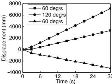
Figure 2-10. Displacements of the mass center of robot’s moving frame along walking direction with different walking speeds. ... 46
Figure 2-13. Different paths generated by the adjustable slider-crank mechanism. ... 48
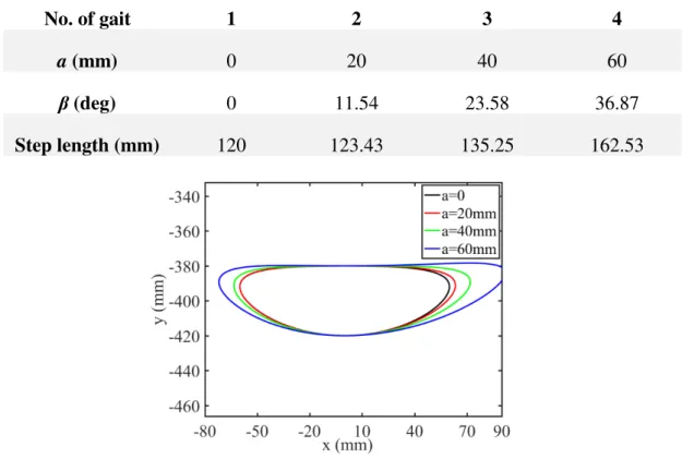
Figure 2-14. Step length with respect to the slider guide position. ... 50
Figure 2-15. ADAMS model of the proposed design. ... 50
Figure 2-16. Different gaits generated by the walking robot. ... 51
Figure 2-17. Snapshots of the simulations with different configuration. ... 52
Figure 2-18. Horizontal displacement of the robot. ... 53
Figure 2-19. Energy consumption with respect to the phase of gait cycle. ... 53
Figure 2-20. Leg mechanism with two output trajectories. ... 54
Figure 2-21. Leg mechanism with a rotated input cam mechanism. ... 55
Figure 2-22. Robot’s body without pantograph mechanism. ... 55
Figure 2-23. ADAMS model of the legged walking robot... 56
Figure 2-24. Horizontal displacement with fixed points: B1 and B2. ... 57
Figure 2-25. Snapshots of simulations with different fixed points of pantograph mechanism. (walking on plane surface) ... 57
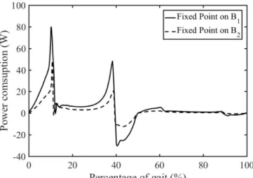
Figure 2-26. Power consumption of the actuator of the left leg when fixed point on B1 and B2 (walking on a plane surface) ... 58
Figure 2-27. Horizontal and vertical displacement when the fixed point on B1 and B2 ... 58
Figure 2-28. Snapshots of simulations with different fixed points of pantograph mechanism. (climbing stairs) ... 59
Figure 2-29. Power consumption of the actuator of the left leg when fixed point on B1 and B2 (climbing stairs) ... 59
Figure 3-1. Gravity compensator with a four-bar linkage. ... 63
Figure 3-2. Moment of the gravitational forces before balancing (a) and the remaining moment after balancing (b). ... 67
Figure 3-3. Gravity compensator by forming a crank-slider mechanism... 68
Figure 3-4. Moment of the gravitational forces before balancing (a) and the remained moment after balancing (b). ... 73
Figure 3-6. Gravity compensator based on the inverted slider crank mechanism. ... 75
Figure 3-7. Active and reaction forces due to the gravitational forces of auxiliary links. ... 77
Figure 3-8. Moment produced by the gravity of the rotating link 2. ... 81
Figure 3-9. Moments produced by the gravity of the rotating link 2 (a) and by the gravity of the linkage with the spring (b). ... 82
Figure 3-10. Residual moments without taking into account the masses of auxiliary links (c) and with them (d). ... 83
Figure 4-1. Rigid frame of the robotic suit. ... 86
Figure 4-2. 3D model of the robotic suit. ... 88
Figure 4-3. Cable locking mechanism. ... 89
Figure 4-4. Planar diagram of the distribution of anchors and attachment points while used wearing the robotic suit. ... 90
Figure 4-5. Gravitational moment on the shoulder(a) and elbow(b) joint when carrying a 10kg load with different postures. ... 94
Figure 4-6. Cable tensions when carrying a 10kg load with different postures. ... 95
Figure 4-7. Force on the user’s shoulder when carrying a 10kg load with different postures. ... 95
Figure 4-8. Optimization procedure. ... 97
Figure 4-9. Cable tensions when carrying a 10kg load with different postures after optimization. ... 97
Figure 4-10. Force on the user’s shoulder when carrying a 10kg load with different postures after optimization. ... 98
Figure 4-11. Workspace of the propose exosuit. ... 99
Figure 4-12. Block diagram of the PD controller with gravity compensation. ... 100
Figure 4-13. Comparison of the actual and desired trajectories. ... 101
Figure 4-16. Cable tensions with respect to the change of forearm flexion angle
(shoulder extension angle is 0°). ... 104
Figure 4-17. Cable tensions with respect to the change of forearm flexion angle (shoulder extension angle is 30°). ... 104
Figure 5-1. Lightweight cobot and HOBM cooperation for handling of heavy parts. ... 109
Figure 5-2. Workspace of the HOBM before (a) and after (b) modification for cooperating with cobot. ... 110
Figure 5-3. Frame of the usual HOBM (a) and its modified version (b) for balancer - lightweight robot cooperation. ... 110
Figure 5-4. Coupled system in which the HOBM is in the singular configuration. .. 111
Figure 5-5. Workspace of the HOBM after modification. ... 111
Figure 5-6. ADAMS model of the coupled system. ... 112
Figure 5-7. Trapezoidal trajectory ... 113
Figure 5-8. Oscillation of the proximal arm of the HOBM ... 114
Figure 5-9. Oscillation of the distal arm of the HOBM ... 114
Figure 5-10. Force applied on the cobot due to the inertia effect of the HOBM ... 115
Figure 5-11. The rigid axis connecting cobot and HOBM. ... 116
Figure 5-12. Comparison of the force applied on the cobot due to the inertia effect of the HOBM before and after the implementation of the rigid axis ... 116
Figure 5-13. Oscillations of the rotating arms of the HOBM after introducing damping moments. ... 118
Figure 5-14. Force applied on the cobot after introducing damping moments ... 118
Figure 5-15. The Denavit–Hartenberg parameterization of the cobot UR10. ... 119
Figure 5-16. Representation of the HOBM ... 123
Figure 5-17. Comparison between the ADAMS and Matlab models ... 126
Figure 5-18. Forces applied on the end effector of HOBM ... 127
Figure 5-19. Forces applied on the end effector of the cobot... 128
Figure 5-22. Maximum angular acceleration of the trajectory with respect to the payload mass when the HOBM and cobot are connected via a telescopic axis ... 131 Figure 5-23. Input torques of the cobot: (a) no damping moments, (b) damping coefficients are 0.4Nms deg and (c) damping coefficients are 0.8Nms deg. ... 133
Figure 5-24. The maximum angular acceleration of the trajectory with respect to the payload mass: (a) no damping moment and (b) damping coefficients are 0.8Nms deg.
... 134 Figure B-1. Simulink model of the robotic suit with PD controller ... 153 Figure C-1. The general system of the cobot-HOBM coupled dynamic model when cobot and HOBM are linked via a telescopic axis ... 155 Figure C-2. The general system of the cobot-HOBM coupled dynamic model after introducing frictions on the HOBM’s joints ... 155
List of Tables
Table 2-1. General Setting of the optimization ... 42
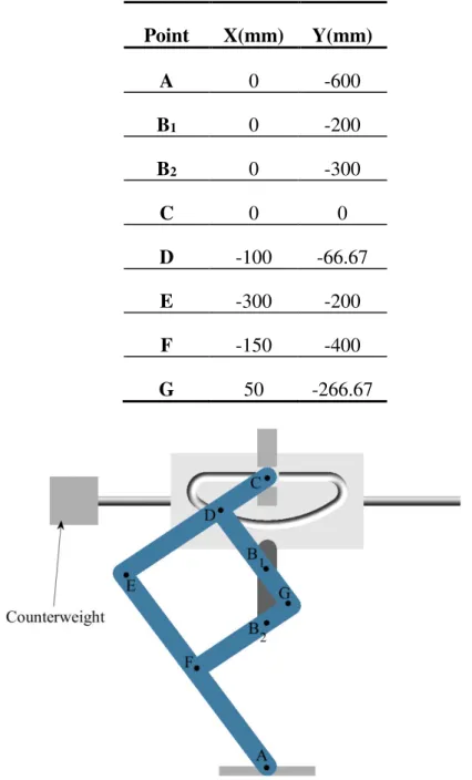
Table 2-2. Variation of adjustable parameters and step length of the leg mechanism 51 Table 2-3. Coordinates of the axes, input and output points of the pantograph mechanism. ... 56
Table 4-1. Body segment parameters of an adult male. ... 93
Table 4-2. Parameters of the trajectories. ... 101
Table 5-1. Parameters of the trajectories. ... 113
Table 5-2. Denavit-Hartenberg parameters of UR10 ... 120
Table 5-3. Mass-inertia characteristics of UR10 ... 123
Table 5-4. Mass-inertia characteristics of the HOBM ... 125
Chapter 1
Introduction
1.1 Legged Walking Robot ... 2 1.2 Gravity Compensation in Robotics ... 8 1.3 Collaborative robotics ... 18 1.4 Outline of the thesis ... 32In the first chapter of the thesis, the critical review of the coupling systems is given. Due to the variety of the coupling system, this chapter is divided into three sections with respect to the nature of the examined problems: legged walking robots, gravity compensators used in robots and collaborative robotics.
It is shown that the design principles used for the development of these devices and robots can be represented as the coupling systems of different mechanical units. The optimal coupling of these units and their improved design can significantly enhance the performance of robots.
The known solutions are summarized through the suggested critical review and some of their drawbacks are disclosed.
1.1
Legged Walking Robot
Since the term “robot” was firstly used by the Czech writer Karel Čapek in his fictional play “R.U.R” in 1920 [1], the robot industry has been through a prosperous development in the past fifty years. As its initial object in the play, a robot is designed as a machine to take place of humans for doing the jobs which are dangerous or physically intensive.
As an important part of robot family, legged robots more versatile than track or wheeled robots when they work in unconventional environments including rough terrains and steeps stairs. However, achieving such versatility require increased complexity and power consumption.
The typical walking consists of a repeated gait cycle. The cycle itself contains two phases: the propelling phase and the non-propelling phase. Figure 1-1 shows a classic two-stage cycle of bipedal walking gait where the thicker line represents the supporting leg (right leg) in propelling (stand) phase and the thin line represents the swing leg (left leg) in non-propelling (swing) phase. While in stand phase, the leg is in contact with the ground and generating a propelling force to push the body moving forward. And while in swing phase, the leg is leaving the ground and swinging from back to forth, the foot trajectory is a curved line.
Figure 1-1. Two-stage step cycle of bipedal walking gait.
In this section, a review of the development of legged walking robots since the born of the first humanoid legged walking robot WABOT 1 is presented.
1.1.1 Multi-degree-of-freedom legged walking robots
The pioneering works in the field of legged robots were started in Japan around 1970. Ichiro Kato and his team at Waseda University designed two bipedal walking robots WL-1 and WL-3 based on a human leg mechanism in 1967 and 1969 respectively [2]. WL-3 (Figure 1-2a) has an electro-hydraulic servomotor and performed humanoid walking locomotion in the swing phase and stance phase using a master-slave control method. While in 1973, they created the world’s first full-scale anthropomorphic legged – WABOT-1 (Figure 1-2b) [3]. WABOT-1 has disproportionately large feet to
maintain its balance. It was hydraulically powered and controlled by a minicomputer and experiment showed that it was able to realize a few slow steps in static equilibrium. Followed by the way paved by Kato, researchers from Waseda University have developed several generations of WL and WABIAN family walking robots where the latest generation named WABIAN-2 (Figure 1-2c) [4], [5]. WABIAN-2 is 1.53m tall and 64.5kg weight, it has 41 DOFs and the joints designed for bio-mimicking the actual human’s one. Experiments showed that it can walk steadily with the speed of 1.8km/h.
(a) WL-3 (b) WABOT-1 (c) WABIAN-2
Figure 1-2. Legged Walking Robot
In the same period with Kato, in Europe, M. Vukobratovic and his team from the Mihailo Puppin Institute, Belgrade, Yugoslavia were very involved in the problems generated by functional rehabilitation. They designed the first active exoskeletons, and several other devices such as the Belgrade’s hand [6], [7]. But the most well-known outcome remains their analysis of locomotion stability, which exhibited around 1972 the concept of zero-moment point (ZMP), widely used since that time [8]. This was the first attempt to formalize the need for dynamical stability of legged robots; the idea was to use the dynamic wrench in order to extend a classical criterion of static balance (the center of mass should project inside the convex hull of contact points).
In the next decade, the breakthroughs came from the United States. Robert McGhee and Kenneth Waldron achieved the design of the world’s largest hexapod which is a man-driven quasi-industrial system able to walk on natural irregular terrain called adaptive suspension vehicle (Figure 1-3d) [9]. The vehicle uses a parallelogram mechanism and two jack actuators for each of its legs. Simultaneously, Marc Raibert started to study dynamically stable running at Carnegie Mellon University. Then, he launched the Massachusetts Institute of Technology LegLab, where he and his teammates designed a 3D one-leg hopper (Figure 1-3e) which can be actively balanced in dynamic locomotion with simple control algorithms [10]. After the one-leg prototype, they also designed a sequence of biped and quadruped versions where the biped hopping machine could even perform a flip [11]–[13].
(d) Adaptive suspension vehicle (e) 3D one-leg hopper (f) Passive biped robot
Figure 1-3. Legged Walking Robot (Continued)
In the 1990s, Tad McGeer pioneered the field of passive walking robots by proposing the idea of studying purely passive mechanical systems (Figure 1-3f). He has shown that there exists a class of two-legged machines for which walking is a natural dynamic mode: once started on a shallow slope, such a machine will settle into a steady gait quite comparable to human walking, without active control or energy input [14]. His work led the way of designing a walking robot by adding a minimum set of actuators to a passive system in order to just compensate for the loss of energy when the system is on flat ground. Because of the energy efficiency of this kind of design, several researchers have followed the tracks open by Tad McGeer [15], [16].
The end of the millennium was a period of intense technological activities. Industrial breakthroughs showed to the world that building true humanoids was now possible. Several international industrial enterprises started to conduct research in the field of humanoid walking robots. In Japan, Honda designed one of the world’s famous humanoid robots - ASIMO (Figure 1-4g) and it was firstly unveiled in 2000 [17], [18]. ASIMO has 34 DOFs and it is the first humanoid robot capable walking and running autonomously with the maximum speed of 2.7km/h at walking and 9km/h at running for the latest version. Similarly, Kawada also designed a series of biped robot and the latest version – HRP-4 (Figure 1-4h) can even accomplish some complicated tasks like dancing and pouring drinks [19], [20]. In recent years, an American robot company, Boston Dynamic, has designed several biped and quadruped robots with great breakthroughs [21]. Its biped robot, Atlas (Figure 1-4i), has an impressive dynamic balancing ability and it can even perform some acrobatic movements like the backward somersault.
(g) ASIMO (h) HRP-4 (i) Atlas
Figure 1-4. Legged Walking Robot (Continued)
1.1.2 Reduced-degree-of-freedom walking robots
To create biped robots walking like a human is necessary to use a large number of actuators. Therefore, these robots are automorphic and flexible. However, there are several drawbacks: complexities of the design and the control system, low energy efficiency due to the masses of motors, as well as an overly high price complicating practical use.
To make a biped robot more attractive, a different methodology can be considered such as constructing a biped robot with reduced number of degrees of freedom. One of the effective ways to design a walking robot with reduced DOFs is to use leg mechanisms which is an assembly of links and joints intended to simulate the walking gait of humans or animals.
Russian mathematician Pafnuty Chebyshev suggested the very first walking machine by using a four-bar mechanism which converts rotational motion to approximate straight-line motion with approximate constant velocity (as known as Chebyshev Linkage). A quadruped prototype of this machine named “The Plantigrade Machine” (Figure 1-5 shows a 3-D reconstruction model) was first shown in Paris on the Exposition Universelle in 1878 [22]. Inspired by the work of Chebyshev, several designs of single DOF walking robot based on Chebyshev linkage have been achieved. Funabashi et al. from the Tokyo Institute of Technology designed a human-driven walking chair where its leg mechanism is a Chebyshev linkage jointed with a pantograph mechanism (Figure 1-6) [23]. The fixed point of the pantograph mechanism can change both vertically and horizontally which gives the possibility to deal with different terrains. Another unique feature of this walking chair is that it has a hybrid actuation system including two assisting actuators for reducing the effects of variations in user’s driving velocity [24]. Similarly, Marco Ceccarelli and his team at the Laboratory of Robotics and Mechatronics in Cassino University have proposed various solutions for Low-Cost Easy-Operation leg design where the Chebichev four-bar linkage has been successively used for generating a foot trajectory (Figure 1-7) [25], [26]. In order to amplify the produced motion of the Chebyshev linkage, a pantograph mechanism has been applied.
Figure 1-5. A 3-D reconstruction model of “The Plantigrade Machine”.
Figure 1-6. A prototype of the walking chair.
Figure 1-7. A prototype of one DOF biped robot built at Cassino University.
Researchers from the University of Maryland has designed a walking mechanism by using a modified four-bar mechanism and a pantograph mechanism (Figure 1-8) [27]. A unique feature of this mechanism is that it contains a leg lift mechanism which can change the position of the fixed point of pantograph mechanism. Hence, this lift mechanism is capable of changing the leg height as well as the stride length. And a few
years later, they designed a six-link leg mechanism which is essentially a four-bar linkage with an embedded skew pantograph [28]. This mechanism can generate a Δ-shaped gait with sufficient height for the walking machine to step over obstacles or to climb stairs. With the embedded pantograph design, the mechanism size can be slender and compact.
Figure 1-8. Leg mechanism of University of Maryland’s walking robot
Except for the four-bar linkage, other linkages have been also used for the design of the single-DOF walking robot. Simionescu and Tempea designed an eight-bar leg mechanism based on Watt II linkage [29]. An RRR dyad was articulated for amplifying the output path. The Klann linkage is another famous leg mechanism designed by Joseph Klann [30], [31]. It has six links including the frame, a crank, two grounded rockers, and two couplers connected by pivot joints. Klann linkage is categorized as a modified Stephenson III kinematic chain and the proportions of each its links are defined to optimize the linearity of the foot for one-half of the rotation of the crank. Several legged walking robots have been designed based on Klann linkage (Figure 1-9) [32]–[34].
Dutch artist Theo Jansen designed a planar single-DOF leg mechanism for his kinetic sculptures “Strandbeest” where he intended to build large mechanisms which are able to move on their own (Figure 1-10) [35]. Jansen’s leg mechanism has 12 links including a crank which is the input of the mechanism and a fixed link which is part of the chassis of the legged system. Several researchers have conducted studies on the kinetic and dynamic of Jansen’s mechanism and some new walking robots have been designed [36]–[39].
(a) The Walking Beast (b) An underwater walking robot
Figure 1-9. Walking robots using Klann linkage.
Figure 1-10. “Strandbeest”
1.2
Gravity Compensation in Robotics
While the industrialization spreading throughout the world from the 19th century, robots
have been a crucial part in manufacture because of their efficiency, high precision and not being restricted by the environment. Since the first commercial industrial robot was brought out by George Devol in 1954 [40], the industry of robot has drastically prospered through the past decades.
The performance of a robotic system is often related to the capacity of the actuator. The dynamic equation of the robotic system is [41]:
Inertial moment Coriolis and centripetal moment Gravitational moment
[ ( ) ( , ) ( ) ]
= + +
τ I θ θ f θ θ G θ (1-1)
where τ is the vector of actuator torques, I the inertia tensor of the robotic system and the inertial moment on each joint is the inertia tensor times the joint acceleration θ , f is the Coriolis and centripetal moment which is a non-linear function of joint position
θ and joint velocity θ and G is the gravitational moment which is a function of θ.
gravitational effect. And since many robotic systems are operated at low speed to ensure the different tasks, gravity compensation would be very beneficial by which a robotic system can be operated with relatively small actuators generating less torque.
A robotic system is statically balanced if its potential energy is constant for all possible configurations. In this condition, robotic systems work similarly in a zero-gravity environment which means that nearly zero actuator forces are required when the mechanism is in slow motion. The static balancing of rotating links, which are often elements of serial or parallel manipulators, is well known. Different approaches and solutions devoted to this problem have been developed and documented [42], [43]. The nature of the compensation force used for balancing of rotation links may be various:
▪ The gravitational force of a counterweight arranged on the opposite side of the rotating link or via an auxiliary linkage;
▪ Forces generated by auxiliary actuators;
▪ The elastic force of a spring jointed directly with links or via an auxiliary mechanism, which can be a cable and pulley arrangement, a linkage, a cam mechanism or a gear train.
1.2.1 Gravity compensation by counterweights
The using of counterweights is one of the classical ways for eliminating gravitational effect in mechanical systems [44], [45]. The application approach is adding counterweights on the rotating links in order to make the total center of mass at a fixed point.
Comparing with the spatial manipulator, gravity compensation by counterweights mounted on the links is more appropriate for serial and planar parallel manipulators (Figure 1-11).
Figure 1-11. Gravity compensation by adding counterweights on links: serial (left)
[46] and planar parallel (right) [47] manipulators.
It is obvious that by directly adding the supplementary mass as a counterweight on the robot is not desirable since it leads to the increase of the total mass and the overall size of the robot. Therefore, in many industrial robots, for example, KUKA R360 and ABB IRB 6700 (Figure 1-12), the masses of the motors are often used for gravity compensation [48].
Figure 1-12. KUKA R360 (left) and ABB IRB 6700 (right).
Except for joining counterweight directly with the initial system, another way of gravity compensation by counterweights is to connect counterweights with original structure via auxiliary linkages. The goal of these linkages is to improve the compensation and design conditions via optimizing the location of balancing elements.
Fukushima et al. designed a mine detection vehicle where a weight balanced manipulator was installed (Figure 1-13a). A counterweight was linked with the manipulator via pantograph mechanism [49]. It has been shown that the robot arm with properly dimensioned balancing counterweights can be efficiently actuated with very low power and energy consumption. Similarly, Bruzzone and Bozzini studied the balancing of the SCARA robot by means of a counterweight via auxiliary linkages (Figure 1-13b) or a spring. The obtained simulation results showed that for low-speed motions the counterweight balancing is more efficient, while for high-speed motions the elastic balancing is advantageous [50].
(a) Mine detection vehicle with weight
balanced arm (b) Gravity compensation of a SCARA robot
Figure 1-13. Gravity compensation by counterweights mounted on the auxiliary
linkage connected with the initial system.
Although many studies illustrate the promising results of gravity balancing of parallel manipulators comprising auxiliary systems equipped with counterweights. However, in reality, such a method often becomes complicated for application because of the limitation of the overall size of manipulators and the possibility of collision of extended moving links carrying counterweights.
1.2.2 Gravity compensation by auxiliary actuators
Because of the limitation of gravity compensation by counterweights, in some designs, pneumatic, hydraulic or electromagnetic actuators are used for the gravity balancing of serial manipulator [51] or parallel robots [52] (Figure 1-14).
Figure 1-14. Gravity compensation by auxiliary actuators.
Lacasse et al. from the University of Laval developed a gravity compensation system for a 7-DOF robotic manipulator using remote counterweights connected to the robot via a hydraulic transmission [53], [54]. The experiment showed that the built prototype of the 7-DOF robot is able to adapt its balancing counterweights to a payload of up to 10 kg, which was a maximal payload for the tested prototype.
It should be noticed that in comparison with the gravity compensation of planar manipulators, the gravity compensation of spatial architectures is more complicated because it can be achieved either by an unavoidable increase of the total mass of moving links or by a considerably complicated design of the initial mechanism. One of the promising approaches is to combine auxiliary linkages with actuators.
Baradat et al. proposed a gravity balancing mechanism for the Delta robot which combines a multi-loop pantograph linkage with actuator. The active force of the actuator generates a vertical force applied to the platform via added linkages [52], [55]. Unlike the previous designs whose object is to eliminate the gravitational effect of the original systems, for the robotic manipulators, another approach is to eliminate the gravitational effect of the payload which is significant when manipulating heavy loads. A method for the automated movement of a gravity-compensated payload and an automated handling system for gravity compensation of the payload were presented by Brudniok et al. (Figure 1-15) [56]. It involves supporting a payload by a holding unit that is connected with an end-effector flange of the robot for automatically moving of the load body. Similar studies were successfully carried out in [57], [58].
Figure 1-15. Automated movement of a gravity-compensated payload.
Another promising application of gravity balancing by using actuators is walking assist devices and rehabilitation exoskeleton. In therapeutic situations, therapists often apply full or partial support to a paretic limb to help reduce the effect of gravity on the patient's motion. For the patients whose muscles are weak or lacks normal neuromuscular control due to a neurological disease like stroke, it is extremely difficult to do during walking, where the weight of the leg may create problems [59].
MoonWalker (Figure 1-16a) is a lower limb exoskeleton [60], which is able to sustain part of a user's body weight. This system can be used for rehabilitation, to help people having weak legs, or to help those suffering from a broken leg to walk. The main characteristic of MoonWalker is that a passive force balancer provides the force to sustain bodyweight. It is controlled using an actuator that requires very low energy to work on flat terrains, as it is used only to shift that force the same side as the leg in stance. That motor is able also to provide a part of the energy to climb stairs or slopes. The authors believe that this approach can help to improve the energetic autonomy of lower limb exoskeletons.
(a) MoonWalker (b) Honda’s walking assist device
Figure 1-16. Walking assistive devices.
Honda's walking assist device (Figure 1-16b) [61] helps support bodyweight to reduce the load on the user's legs while walking. This could lead to reduced fatigue and less physical exertion. Honda's device lightens the load on the user's legs and helps maintain a center of gravity via special mechanisms developed by the company. There are plenty
of use cases for this product helping people afflicted with mobility issues or leg problems. It can also be used for rehabilitation.
1.2.3 Gravity compensation by springs and auxiliary mechanisms
As was mentioned above, for an equilibrium system, its total potential energy stays constant at any of its configurations. The spring as an element which has the property of storing and releasing energy is often used for gravity balancing. For a robotic system balanced with springs, the gravitational potential energy of the robot system and the elastic potential energy of the spring transfer between each other, hence the total potential energy can stay as a constant.
Before introducing gravity balancing mechanisms by spring, let us firstly disclose the differences of two types of springs which are used for gravity compensation in robotic systems: zero-free length and non-zero-free length springs.
Zero-free length spring is a term for a specially designed coil spring that would exert zero force if it had zero length. Whereas for the non-zero-free length spring, zero force will be exerted at its non-zero initial length.
Obviously, a coil spring cannot contract to zero length because at some point the coils will touch each other and the spring will not be able to shorten any more. Zero-length springs are made by manufacturing a coil spring with built-in tension, so if it could contract further, the equilibrium point of the spring, the point at which its restoring force is zero, occurs at a length of zero [62]. The force-length characteristics of springs of these two types of springs are shown in Figure 1-17.
Figure 1-17. Force-length characteristics of springs.
In order to better understand the difference between the gravity compensation by zero-free and non-zero-zero-free length springs, let us consider the gravity compensation of a rotating link by directly linking a spring.
Figure 1-18. Gravity balancing by spring directly linked with the rotating link.
For the system shown in Figure 1-18, the system will be fully balanced if the moment of the gravitational forces equals to the moment of the elastic force of the spring, i.e.
(
)
sin sp / sin
mgs = F ar l (1-2)
where m is the mass of the rotating link, s = los is the distance of gravity center S from
axis O, φ is the angle between the vertical axis and the link axis, Fsp = F0 + k(l – l0) is
the elastic force of the spring, F0 is the initial force of the spring (the initial force is the
internal force that holds the coils tightly together), k is the stiffness coefficient of the spring, l0 is the initial length of the spring, a = lOB is the distance of point B from axis
O, r = lOA is the distance of point A from axis O and l = lAB is the length of the spring
at current angle φ.
It can be seen from Equation (1-2) that a fully gravity compensation can be achieved when F0= kl0, i.e. when a zero free length spring is used. In the case of a non-zero-free
length springs with F0 = 0 or F0 ≠ kl0, only partial gravity compensation of a rotating
link can be achieved.
However, zero-free-length springs are often applied in theoretical solutions, but they are very rare in real robotic structures. Therefore, the use of conventional linear springs for gravity compensation often considered with auxiliary mechanisms. The additional parameters of the auxiliary mechanisms can be used for optimizing gravity compensation efficiency.
A simple scheme of gravity compensation by a spring and an auxiliary mechanism is shown in Figure 1-19. The adding of the cable and pulley allows full compensation of gravity by using non-zero-free length spring. The condition of the gravity compensation of the rotating link can be rewritten as:
sin sp
mgs =F h (1-3)
where h=(ar/lAB)sinφ. Thus, Expression (1-3) is similar to (1-2) when the length l of
consider that lAB=l - l0, which leads to the condition mgs = kar, with F0=0. So, the
rotating link can be balanced with non-zero-free length spring.
Figure 1-19. Gravity compensation by a spring joined with a pulley and a cable.
Apart from using the conventional round pulley, Endo et al. designed a gravity compensation mechanism with non-circular pulleys and springs. After the preliminary verification of the design methodology for a single pendulum system, the authors extend the compensation mechanism to four-bar and five-bar linkage arms. It has been shown that the introduction of the weight compensation mechanism reduces the maximum static torque up to 50-80% [63].
Although theoretically, the method of joining springs with pulley-cable mechanism is an effective approach for gravity compensation, several error sources in the practical implementations decrease the actual efficiency [64]. The condition of maximum elongation of the spring that should be not more than 25% of its initial length leads to the design concept, in which the spring must often be installed along the rotating arm and the number of pulleys should be at least two. Considering the diameter of the cable with protection, the diameter of the pulley turns out to be relatively large, which leads to a perturbation of the theoretical conditions of the balancing. Furthermore, the frictional forces between the pulley and the cable are also not low. All these factors lead to an unbalanced moment of more than 10-15% of the moment of gravitational forces. Except for cable-pulley arrangement, gravity balancing systems with non-zero-free length spring are often considered with auxiliary linkages as well.
Figure 1-20 shows two gravity equilibrators based on inversed slider-crank mechanisms [65], [66]. In the left system, rotating link 1 is connected with coulisse 2 and slider 3. The elastic force generated by the compression spring 4 is proportional to sin(φ/2)
which let the whole system fully balanced. And in the right design, the lengths of links of the mechanism must satisfy to the condition lOA = lOB leading to the displacement of
the spring proportional to sin(φ/2), which ensure the complete gravity compensation of
Figure 1-20. Gravity compensation based on inversed slider-crank mechanisms.
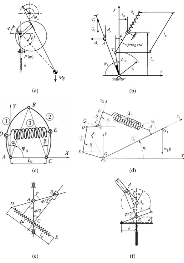
Several of the other design concepts carried out by adding auxiliary linkages are shown in Figure 1-21 [67]–[71]. In these designs, the geometrical dimensions of the auxiliary linkages, i.e. the lengths of the links, are functioned as adjustable parameters. While changing these parameters, the relationship between the rotational angle of the balanced link and the length of the spring will be changed as well. Numerical minimization methods are used for obtaining optimal parameters.
Gravity compensation with springs can be also applied for upper-limb or lower-limb rehabilitation. Unlike the rehabilitation devices driven by motors, for the designs with springs, no external active force (or low active force for hybrid designs) is needed. Hence, these designs will not be affected by the size of the motors or battery duration etc.
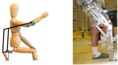
Figure 1-22 shows two rehabilitation devices by using springs for upper limb and lower limb respectively [72], [73]. For the upper-limb design, a parallelogram linkage joined with two springs was used for the gravity compensation of the whole arm. While for the lower-limb design, a hybrid method was employed where the center of mass of the leg is geometrically located using a parallelogram mechanism and then the springs are placed at suitable positions in order to fully compensate the effect of gravity over the range of motion. A hybrid design was also proposed where a motor was added for compensating the errors caused by friction [74].
(a) (b)
(c) (d)
(e) (f)
Figure 1-22. Upper-limb and lower-limb rehabilitation devices by using springs.
In several designs, cam mechanism joint with linear springs were used for gravity balanced where the optimal profiles of cams were found in order to compensate the gravity of links or a payload [41], [75]. In addition, for some multi-DOF manipulators, gear trains like bevel gears were used for the gravity compensation of each link of the manipulators [76], [77].
1.3
Collaborative robotics
In the past decades, our society benefits a lot from the booming development of the robotic industry. With the automatic systems and pre-programmed settings, robots can accomplish plenty of tasks more efficiently, and the physical burdens of human have also been relieved.
However, up to now, there are still some tasks which cannot be fully automatized (due to the complexity of the task or the unpredictability of the workspace) or need the involvement of human. But for these tasks, robots can still be beneficial while working with human and sharing the same workspace and we call these robots - collaborative robots or cobots (the portmanteau of collaborative robots). Cobots were invented in 1996 by Colgate and Peshkin, professors at Northwestern University. A 1997 US patent filing describes cobot as "an apparatus and method for direct physical interaction between a person and a general purpose manipulator controlled by a computer" [78]. Despite its very specific initial meaning, the word cobot now often refers to the robot having direct interaction with the human within a shared workspace. Cobots provide a variety of benefits such as weight compensation, inertia masking, strength amplification, and guidance via virtual surfaces and paths [79].
In this section, a brief review of three kinds of widely-used cobots: hand-operated balanced manipulators, wearable robotic devices and collaborative industrial robots is proposed.
1.3.1 Hand-operated balanced manipulator (HOBM)
mechanization of production. HOBM is a handling system with a simple mechanical actuator in which the manipulated object in any position of the workspace is balanced. Such a state of constant balance allows displacements of heavy objects manually. HOBMs are used in such conditions as when the application of hoisting machinery is not efficient and automation by using industrial robots is expensive and consequently unjustified. [80]
The creation and industrial application of HOBM began in 1964 when Robert A. Olsen suggested a new original balanced assembly [81], [82] (Figure 1-23). This invention was the basis for the development of the manual balanced manipulator proposed by Reizou Matsumoto in 1975 (Figure 1-24) which is the prototype of the modern HOBM [83] (Figure 1-24).
Figure 1-23. HOMBs designed by Robert A. Olsen.
Figure 1-24. HOMB in [84]. Figure 1-25. HOBM «KCH-160».
In the suggested solution of Reizou Matsumoto, the following property of the pantograph is used: if three points (see Figure 1-24: points 5, 6 and 7) of the pantograph lie on the same straight line A-A, then any path traced by point 5 is reproduced by point 7 (for fixed point 6) and any path traced by point 6 is reproduced by point 7 (for fixed point 5). Thus, if points 5 and 6 are located in the vertical and horizontal guides, the displacement of point 7 in the horizontal plane may be realized by the horizontal
displacement of point 6 combined with the rotation of the system about the vertical axis (for fixed point 5). In a similar manner, the vertical displacement of point 7 may be realized by the vertical displacement of point 5 (for fixed point 6). The interesting characteristic of such a system is the following: if the pantograph system is balanced about axis through point 5, the displacements of the manipulated object in the horizontal plane may be realized without effort (the only resistance being due to friction in the joints) because the gravitational forces are always perpendicular to the displacements. Thus, the displacements in the horizontal plane may be realized manually. For the vertical displacement, a suitable driver may be used, which can balance the weight of the manipulated object or produce the vertical displacement directly.
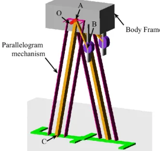
The pantograph applications are often used in the HOBMs since they allow the transformation of the small displacements into the large displacements. For example, in Figure 1-26, the small displacements of the points A and B lead to a large displacement at the end effector G, which gives a large working space to the manipulator.
Figure 1-26. HOBM with pantograph actuator.
The term "balanced manipulator" shows that, for the HOBMs, in the operating procedure of these systems, it is very important to achieve an accurate mass balancing. The general approach for determination of balancing conditions was proposed by the study of the motion of the center of mass of the pantograph actuator.
It should be noticed that the basic function of a HOBM is that operators can move the manipulated object horizontally, overcoming only the forces of friction, the total work done by the forces of gravity of the elements of the actuator must be equal to zero. For this purpose, the center of mass of the pantograph mechanism must only move in the horizontal direction (or must be fixed).
Which are the advantages of these manipulators relative to industrial robots? Primarily it is the simplicity of their construction and the low-cost price. They have a very simple command system, a great weight-carrying capacity (up to 2500 kg) and a very large workspace (in the horizontal direction the gripper can reach to approximately 3000mm). This allows the HOBM to be used for moving workpieces between machine tools very smoothly because it is controlled manually. The implantation of HOBM in existing production is very simple without the need for important additional surfaces,
It is obvious that the balancing condition achieved by a counterweight leads to a significant augmentation of the inertia of the whole system which increases the effort for manipulation. Therefore, instead of using a counterweight, there are also balancing schemes based on the application of springs (Figure 1-27). [83], [85]–[87]
Figure 1-27. Balancing schemes with springs.
It should be noticed that, during the usage of HOBM, most of the works are used to overcome the frictional forces. Therefore, how to diminish friction is one of the essential parts in the design process of a HOBM. Practical applications show that the operation of the manual balanced manipulator is easier when the mechanical actuator contains only revolute pairs. In this case, the frictional forces are low and, consequently, the manual effort exerted by the operator is less. Figure 1-28 shows a version of a manual balanced manipulator with only revolute pairs [88], [89]. It can be seen that, in these designs, pneumatic/hydraulic actuators were used.
The design of the drive system in manual balanced manipulators also determines the construction of the manipulator, its functional capacity, as well as its reliability and speed. In industry, one can find manipulators with electric, pneumatic and hydraulic drives. For manipulators having up to 150 kg load capacity, one uses electric motors or pneumatic drives; if the load capacity is up to 500 kg one uses electric motors. With regard to manipulators with very great load capacity (up to 2500 kg), essentially one uses hydraulic drives.
Figure 1-28. HOBM with parallelogram mechanism.
Figure 1-29. Some examples of HOBM applications («dalmec» Italy).
The applicability of HOBM in the different fields is very wide, including: loading and unloading of machine tools, presses and other production equipment; displacement of heavy objects during machine assembly; movement of foundry ladles; handling of heavy objects as, for example electric motors, various devices, etc.; as well as handling of objects during storage. Figure 1-29 represents some examples of their application.
1.3.2 Wearable robotic devices for power assistance and rehabilitation
The wearable robotic devices, also known as exoskeleton, have strong advantages given their unique features such as their outstanding physical performance, exceeding that of humans, and their mobility. As a result, attempts to adopt these devices in the rehabilitation and the industrial field provide a huge benefit for their users [90].
Assistive robots have applications in the industrial field as well as for patients and the elderly with mobility impairments. They free people from much labor and the burdens of many kinds of manual work. There have been many approaches to the reduction of labor that do not only fully assist but also partly aid workers, such as in the use of extremely heavy payload-oriented construction equipment, which is manipulated by humans. Manual or semi-automatic machine tools are mostly used in contemporary industries. In particular, without manpower, especially without the manipulability and mobility of human limbs, full automation will be incompatible with today’s technologies.
According to which part of the user’s body is assisted, the exoskeletons can be divided into two classes: lower-limb designs and upper-limb designs.
(a) Lower-limb designs
Locomotor disability is the most commonly reported type of disability. It is defined as a person's inability to execute distinctive activities associated with moving both himself and objects, from place to place and such inability resulting from the affliction of the musculoskeletal and/or nervous system. All over the world, several dozen million people suffer from the effects of post-polio, multiple sclerosis, spinal cord injury, cerebral palsy, paraplegia, quadriplegia, muscular dystrophy etc. and could benefit from the advances in robotic devices for rehabilitation [91]. The temporary or permanent loss of human motor functions can be compensated by means of various rehabilitation and assistive devices.
Wearable robotic systems or exoskeletons for rehabilitation or for walking assistance in daily living offer real advantages. In the last decade, the interest in this field has raised mainly due to the growing demand caused by an increasing number of lower-limb disabled patients.
Hybrid Assistive Limb (HAL, Figure 1-30a) is an exoskeleton that is targeted for both performance-augmenting: heavy works, physical training support and rehabilitative purposes [92], [93]. HAL employs controller, computer, harmonic drive motors at the hip, knee, and ankle joints. Power for the motors is supplied by a battery pack mounted on the backpack. HAL system utilizes a number of sensors for control: skin-surface EMG electrodes (Electromyographic electrodes for measuring the activation level of the muscles), potentiometers for joint angle measurement, ground reaction force sensors, a gyroscope, and accelerometer mounted on the backpack for torso posture estimation. The total weight of the device is 21kg. HAL supports activities like standing up from a chair, walking, climbing up and down stairs.
Similarly, ARGO Medical Technologies Ltd. designed a wearable, motorized quasi-robotic exoskeleton that can be used for therapeutic activities named ReWalk (Figure
1-30b) [94]. ReWalk comprises light wearable brace support suit, which integrates DC motors at the joints, rechargeable batteries, an array of sensors, and a computer-based control system. Upper-body movements of the user are detected and used to initiate and maintain walking processes. ReWalk allows paraplegic patients to walk, sit and stand-up, climb up and down the stairs. It lacks body weight support and stability, hence for that reason, there is a need to utilize crutches, to maintain upright position and balance.
(a) HAL (b) ReWalk (c) WADBSA
(d) WADSM (e) X1
Figure 1-30. Exoskeletons for walking assistance and rehabilitation.
Japanese company Honda has several devices for walking assistance. One of them named Walking Assist Device with Bodyweight Support Assist (WADBSA, Figure 1-30c) helps support bodyweight to reduce the load on the user's legs while walking [61]. This could lead to reduced fatigue and less physical exertion. The device comprises of 2 motors and gears, rechargeable lithium-ion batteries, control computer, shoes with foot force sensors and a seat. The motors can lighten the load on the user's legs and helps maintain a center of gravity via special mechanisms developed by the company. There is plenty of use cases for this product, not the least of which would be helping industrial workers, people afflicted with mobility issues or leg problems. It can also be used for rehabilitation. Another exoskeleton designed by Honda is Walking Assistive Device with Stride Management (WADS, Figure 1-30d) [95]. This device is developed for patients with weakened leg muscles who are still able to walk. It is comprised of 2 brushless DC motors, rechargeable lithium-ion battery, angle sensors, control computer and operates about 2 hours. A motor helps lift each leg at the thigh as it moves forward and backward. This helps lengthen the user’s stride, making it easier to cover longer distances at a greater speed. Its lightweight and simple design with a