Publisher’s version / Version de l'éditeur:
Vous avez des questions? Nous pouvons vous aider. Pour communiquer directement avec un auteur, consultez la
première page de la revue dans laquelle son article a été publié afin de trouver ses coordonnées. Si vous n’arrivez pas à les repérer, communiquez avec nous à [email protected].
Questions? Contact the NRC Publications Archive team at
[email protected]. If you wish to email the authors directly, please see the first page of the publication for their contact information.
https://publications-cnrc.canada.ca/fra/droits
L’accès à ce site Web et l’utilisation de son contenu sont assujettis aux conditions présentées dans le site LISEZ CES CONDITIONS ATTENTIVEMENT AVANT D’UTILISER CE SITE WEB.
Student Report (National Research Council of Canada. Institute for Ocean Technology); no. SR-2006-11, 2006
READ THESE TERMS AND CONDITIONS CAREFULLY BEFORE USING THIS WEBSITE. https://nrc-publications.canada.ca/eng/copyright
NRC Publications Archive Record / Notice des Archives des publications du CNRC :
https://nrc-publications.canada.ca/eng/view/object/?id=05e1d9b9-0e8f-4fcb-a0f4-829877e6fed0 https://publications-cnrc.canada.ca/fra/voir/objet/?id=05e1d9b9-0e8f-4fcb-a0f4-829877e6fed0
NRC Publications Archive
Archives des publications du CNRC
For the publisher’s version, please access the DOI link below./ Pour consulter la version de l’éditeur, utilisez le lien DOI ci-dessous.
https://doi.org/10.4224/8895463
Access and use of this website and the material on it are subject to the Terms and Conditions set forth at Ice detection laser modification, 2006
DOCUMENTATION PAGE
REPORT NUMBER
SR-2006-11
NRC REPORT NUMBER DATE
April 2006
REPORT SECURITY CLASSIFICATION
unclassified
DISTRIBUTION
unlimited
TITLE
Ice Detection Laser Modification, 2006
AUTHOR(S)
T.Osmond
CORPORATE AUTHOR(S)/PERFORMING AGENCY(S)
Institute for Ocean Technology
PUBLICATION
SPONSORING AGENCY(S)
IOT PROJECT NUMBER
42_2096_10
PAGES
11
KEY WORDS
Laser, Ice Detection APP A-D FIGS.5 TABLES0
SUMMARY
This document contains the following design work regarding the IOT Ice Detection Laser: - Attaching a timing belt and pulleys to the focus dial of the laser to that the focus of
the laser may be controlled remotely,
- Mounting the Laser and a camera on a base plate as a single unit,
- Design of a weather resistant housing to protect the laser and camera from wind and rain.
ADDRESS National Research Council
Institute for Ocean Technology Arctic Avenue, P. O. Box 12093 St. John's, NL A1B 3T5
National Research Council Conseil national de recherches Canada Canada Institute for Ocean Institut des technologies
Technology océaniques
ICE DETECTION LASER MODIFICATION, 2006
SR-2006-11
T. Osmond April 2006
Summary
Ongoing within the Institute for Ocean technology as of the first quarter of 2006, is a research project centered around Institute patented technology developed for Ice Monitoring and Measuring. As part of the Ice Monitoring and Measuring project under the project lead of Robert Gagnon, a laser is controlled from a remote location. It must be controlled and pointed at ice from distances as far away as several hundred feet. There are several modifications and features needed for the laser to be used in the Ice Monitoring and Measuring project. First of all, the operator must have pointing direction control over the laser via remote control. Second, one must be able to focus the laser remotely. And lastly the laser must be contained with a power supply and a video feed camera in a weather resistant housing so that the device can operate in wet weather. Automating the direction of the laser has been accomplished by purchasing a mechanism that allows for remote control of pan and tilt angles. To this
mechanism, the weather resistant housing will attach. The tasks of designing the weather resistant housing and the remote control adjustment control over the focus of the laser came to the Design and Fabrication group within the Institute. This report details these designs.
TABLE OF CONTENTS 1.0 – Design Criteria ...3 2.0 – Components...5 3.0 – Calculations ...6 4.0 – Figures...7 5.0 – Appendices ...12 2
1.0 – Design Criteria
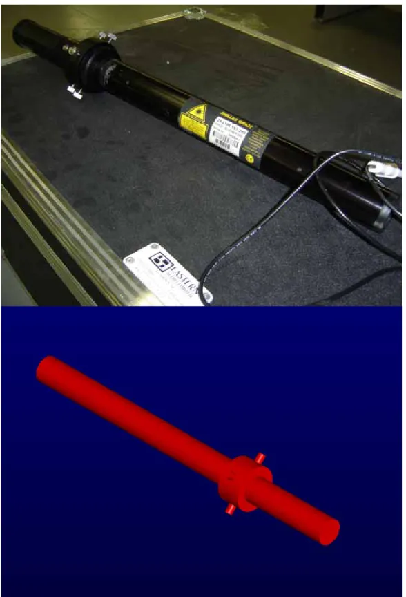
The laser being used in the Ice Monitoring and Measuring project is a long cylindrically shaped device approximately 24 inches in length and 1.74 inches in diameter, shown in Figure 1. There are focusing screws in the front third of the laser and just ahead of those screws there is a dial that is designed to be turned with the fingers. A small experiment was conducted and it was measured to require approximately 18.9 oz.in of torque to turn the focus dial. It was also decided that approximately 180 degrees of rotation would offer a sufficient range of focus for the Ice Measurement project purposes.
The electro-mechanical device capable of turning the focus dial on the laser proposed by the electronics department is a HiTec HS-785HB Winch Servo (see figure 2). The servo offers 152.75 oz.in of torque, significant strength in shear and at least 1080 degrees rotational range (three rotations). The electronics department claim to be capable of achieving about 1800 degrees rotation (five rotations) using their own drive controller. These parameters define the design criteria for the remote laser focus control.
The challenge was to connect the winch servo to the focus dial translating approximately three rotations on the winch servo into a half turn or 180 degrees rotation on the laser dial without exceeding torque capacity.
The basic concept used to meet this challenge is a system of toothed pulleys and a single sized, trapezoidal-toothed timing belt. One pulley is connected to the servo and another is locked onto the focus dial. A third pulley called the idler is used on the opposite side of the servo to reduce the load on the laser when the timing belt is tightened.
We now have the challenge of tightening the timing belt. This is accomplished by attaching the servo to an adjustable rail that moves up and down in a slot. There are two parts of the adjustable rail, the static piece and the dynamic piece. Tightening the timing belt is simply a matter of tightening the nut on the
adjustment screw coming out of the top of the static piece of the rail (see figure 3). A locking screw on the back of the static piece of the rail locks the system in place so that the timing belt will not loosen over time. This whole system of rail and servo is thus attached to the laser.
A split clamp (see figure 4) is used as the connecting mechanism between the Laser and the Servo. The split clamp is also used to hold the laser in place within the housing. The split clamp bolts to a base plate that in turn screws into the housing floor.
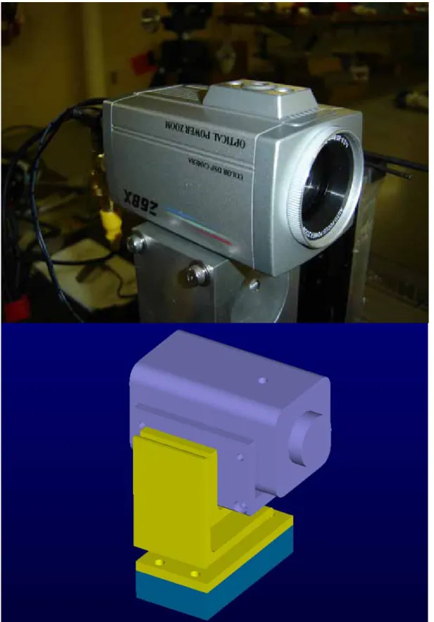
Also connected to the base plate is the video feed camera (see figure 5). The camera sits on an adjustable pan\ tilt stand purchased to allow the camera to be adjusted to point in the correct direction and locked in place. It is intended that
the camera should only need to be adjusted once so that it points in line with the laser and should be left in that position for extended periods of time.
The base place attaches to the bottom of the housing using several screws. Because the camera and laser both mount to the base plate it is intended that if necessary the base plate can be removed and returned to the housing without disturbing the alignment between the laser and the camera nor without needing to readjust the timing belt.
The housing for the laser and camera is a modified design of another housing that has already been used at the Institute for Ocean Technology. A larger
housing was used for another Ice Measuring system and the design was found to function properly. Only the dimensions of this newer housing have been
changed.
The weather resistant housing is shown in dwg 2096T14 contained in Appendix A. It is primarily composed of lexan. It has a thick bottom to which the base plate for the laser is screwed. Buckles on the side of the housing tighten the top down. The back of the housing has a hinged door that opens down with hinges on the bottom edge. A waterproof hatch is attached to the door so that minor adjustments to the inner contents of the housing may be made if necessary. The front face of the housing contains a slot for glass to be installed. Optical glass will be used as the medium through which the laser beam will pass upon exiting the housing. The top of the housing has an overhanging ledge to protect the front glass to a certain extent from rain falling straight down.
2.0 – Components
There are a number of mechanical and electrical components needed for the laser aspect of the Ice Monitoring and Measuring project. There are components that have been purchased or fabricated by the Institute already and there are components in need of fabrication. There are also components that are to be purchased, some of which require some modifications. All components in need of fabrication or modification have associated drawings included under source file CAD_User:\Projects\42_2096 Ice Detection\TOsmond\Laser.ckd and are
contained in Appendix A.
Already in possession by the Institute: A 15 mW Melles Griot Laser,
An Optical Power Zoom Color DSP Camera, A pan/tilt adjusting mount for the camera,
A HiTec HS-785HB Winch Servo that will be used to adjust the focus dial of the laser.
The Institute has also already purchased a remote pan/tilt adjusting mechanism to which the weather resistant housing will mount.
Three pulleys, a timing belt and a clevis pin must be ordered from McMaster-Carr (see Appendix D). Order: 2 x 6495K711, 1 x 57105K27, 1 x 6484K222, 1 x 92735A160.
Two of the pulleys must be bored out to larger diameters as shown in drawings 2096T12, and 2096T13.
The weather resistant housing for the entire system must be fabricated. The housing will be composed mostly of lexan, dwg 2096T14 – 2096T23.
Other components needing to be fabricated include:
Two pieces for the adjustable rail, dwg 2096T01, 2096T02,
Components to which the servo will attach, dwg 2096T03 – 2096T05, An Angle bar piece connecting the rail to the split clamp, dwg 2096T06, A spit clamp, dwg 2096T07,
A base plate, dwg 2096T11, Two idler brackets, dwg 2096T08.
And mounting bases for both the laser and camera, dwg 2096T09, 2096T10. A list of all the fasteners needed to fully assemble all components is contained in Appendix C.
3.0 – Calculations Pulley Gear Ratio
Servo Pulley – Pitch Diameter: 0.637” Laser Pulley – Pitch Diameter: 2.292” Ratio: 2.292:0.637 = 3.6:1.0
Thus 3.6 rotations of the servo will provide a complete rotation of the laser focus dial.
Torque Ratio
Maximum torque for servo: 152.75 oz.in.
Minimum required torque to turn focus dial: 18.9 oz.in 152.75 oz.in * 3.6 = 549.9 oz.in
549.9 oz >> 18.9 oz.in
Therefore we have acceptable torque from the servo to turn laser focus dial. Length of Timing Belt
The length of the timing belt was calculated from the dimensions contained in appendix B taken directly from the laser CAD file.
The following calculations were used to determine the necessary belt length: 142° * π / 180 = 2.478 rads θ r = 2.478 * 0.319 = 0.790 “ 133° * π / 180 = 2.321 rads θ r = 2.321 * 0.319 = 0.740” 42° * π / 180 = 0.733 rads θ r = 0.733 * 1.146 = 0.840” 2 * 2.425” = 4.850” 2 * 1.889” = 3.778” 2 * 0.840” = 1.680” 1 * 0.790” = 0.790” 1 * 0.740” = 0.740” 11.838”
Because the timing belt may be adjusted to within a range of 0.75” it is clear that a 12” timing belt is the suitable length.
4.0 – Figures
Figure 1 – Ice Measuring Laser
Figure 2 – Winch Servo
Adjusting Screws
Figure 3 – Timing Belt Adjustment Screws
Figure 4 – Split Clamp Used to Hold Laser
Figure 5 – Camera and Pan/Tilt Mechanism
5.0 – Appendices Appendix A – Drawings
Appendix B – Timing Belt Dimensions Appendix C – Fastener List
Appendix D – Data Sheets
Appendix C – Fastener List
Number Type Length Connecting… Head
LASER
4 8-32 0.500 Angle Bar to Laser Lock Hex
4 8-32 2.000 Laser Lock Together Hex
4 8-32 0.625 Angle Bar to Adjuster Hex
1 8-32 1.500 Two adjusting pieces (sliding screw) Hex
1 8-32 1.500 horizontal adjusting screw Hex
8 4-40 1.000 servomount pieces slot flat csk
4 2-56 0.500 servo to servomount socket screw
8 8-32 0.625 mounts to base plate slot flat csk 7 1/4-20 0.500 base plate to housing bottom socket screw
WEATHER HOUSING
10 8-32 0.625 front glass and back door to housing socket screw 4 1/2-20 0.500 tilt/pan head to stand button slot