Publisher’s version / Version de l'éditeur:
Vous avez des questions? Nous pouvons vous aider. Pour communiquer directement avec un auteur, consultez la Questions? Contact the NRC Publications Archive team at
PublicationsArchive-ArchivesPublications@nrc-cnrc.gc.ca. If you wish to email the authors directly, please see the first page of the publication for their contact information.
https://publications-cnrc.canada.ca/fra/droits
L’accès à ce site Web et l’utilisation de son contenu sont assujettis aux conditions présentées dans le site LISEZ CES CONDITIONS ATTENTIVEMENT AVANT D’UTILISER CE SITE WEB.
2007 PCI National Bridge Conference [Proceedings], pp. 1-20, 2007-10-21
READ THESE TERMS AND CONDITIONS CAREFULLY BEFORE USING THIS WEBSITE. https://nrc-publications.canada.ca/eng/copyright
NRC Publications Archive Record / Notice des Archives des publications du CNRC : https://nrc-publications.canada.ca/eng/view/object/?id=9fc45d71-11b0-4a9b-931c-fc0590b5def5 https://publications-cnrc.canada.ca/fra/voir/objet/?id=9fc45d71-11b0-4a9b-931c-fc0590b5def5
This publication could be one of several versions: author’s original, accepted manuscript or the publisher’s version. / La version de cette publication peut être l’une des suivantes : la version prépublication de l’auteur, la version acceptée du manuscrit ou la version de l’éditeur.
Access and use of this website and the material on it are subject to the Terms and Conditions set forth at
Innovative precast bridge superstructure using ultra high performance concrete girders
I n n o v a t i v e p r e c a s t b r i d g e s u p e r s t r u c t u r e
u s i n g u l t r a h i g h p e r f o r m a n c e c o n c r e t e
g i r d e r s
N R C C - 4 9 6 8 5
A l m a n s o u r , H . ; L o u n i s , Z .
A version of this document is published in / Une version de ce document se trouve dans: Proceedings of the PCI National Bridge Conference, Phoenix, Arizona, Oct. 22-24, 2007, pp. 1-21
The material in this document is covered by the provisions of the Copyright Act, by Canadian laws, policies, regulations and international agreements. Such provisions serve to identify the information source and, in specific instances, to prohibit reproduction of materials without written permission. For more information visit http://laws.justice.gc.ca/en/showtdm/cs/C-42
Les renseignements dans ce document sont protégés par la Loi sur le droit d'auteur, par les lois, les politiques et les règlements du Canada et des accords internationaux. Ces dispositions permettent d'identifier la source de l'information et, dans certains cas, d'interdire la copie de documents sans permission écrite. Pour obtenir de plus amples renseignements : http://lois.justice.gc.ca/fr/showtdm/cs/C-42
INNOVATIVE PRECAST BRIDGE SUPERSTRUCTURE USING
ULTRA HIGH PERFORMANCE CONCRETE GIRDERS
Husham Almansour and Zoubir Lounis
Institute for Research in Construction, National Research Council, Ottawa, Canada
ABSTRACT
The aging and deterioration of highway bridges in North America and the new requirements for building durable and sustainable bridges present technical and economic challenges for owners and designers. An innovative bridge solution is proposed, which introduces a new hybrid superstructure system utilizing ultra high performance concrete (UHPC) for the girders and normal high performance concrete (HPC) for the deck. Such a system will enable bridges with longer service lives, longer spans, lighter weights, and lower maintenance costs over their life cycles. Presently no holistic structural evaluation or design methodology for this type of construction has been developed yet. In this study, the optimum use of UHPC is evaluated for the case of two and three lanes simply supported bridges and for the following two superstructure designs: (i) typical cast in place concrete slab on precast/prestressed HPC girders bridge; and (ii) typical cast in place concrete slab on precast/prestressed UHPC girders. HPC and UHPC bridges are designed for no cracking at the serviceability limit state and satisfying the CHBDC and AFGC-IR-02 requirements and recommendations. The superstructure design is achieved through an iterative design procedure with two major steps: (i) a preliminary design using simplified analysis methods; and (ii) a refined analysis using finite element to check the adequacy of the preliminary design and revise it if necessary. The stress distributions and stress concentration zones in the girders under dead loads and CHBDC traffic loads are thoroughly studied. The number of girders, girder size, and the area of prestressing steel are optimized for minimum use of the materials.
This study shows that the use of UHPC enables a significant reduction in the concrete volume of up to 49% for CPCI 1200 and 65% for CPCI 900 girders. The total areas of prestressing steel required for UHPC-CPCI 900 are 42% and 39% higher than those of CPCI 1400 and CPCI 1600, respectively for span lengths between 35 m and 45 m. The minimum prestressing steel area required for the UHPC-CPCI 900 is only 14% higher than that of UHPC-CPCI 1200, while the reduction of the concrete volume is about 33%.
Keywords: Ultra-high performance concrete, precast/prestressed bridge girder, finite
INTRODUCTION
The aging and deterioration of highway bridges in North America, and the new requirements for building more durable bridges and conservation of raw materials, present technical and economic challenges for owners and designers. In the last four decades, there was a considerable growth in the use of high strength/high performance concrete (HSC/HPC) in highway bridges. It enabled to expand the service life of bridges and build lighter superstructure and longer spans. The benefits of using HSC/HSC to extend the span length or reduce the weight of simply supported precast girder bridge systems reach a limit at about 50 MPa, beyond which there only marginal improvement as the governing design criterion is the condition of no cracking at service(1,2). The benefits of using HPC/HSC can be maximized further if segmental construction is used and splicing of precast girders by post-tensioning in-place(2).
High performance concrete (HPC) can be achieved through the use of low water-cement ratio and/or through the addition of additional cementing materials such as fly ash, slag, or silica fume or a combination thereof. HPC provides high compressive strength, low permeability and low chloride diffusivity, improved freeze-thaw resistance. The U.S. Federal Highway Administration defines high performance concrete through eight performance characteristics: freeze-thaw resistance, scaling resistance, abrasion resistance, chloride penetration, compressive strength, modulus of elasticity, shrinkage and creep(3). HPC can be defined as a concrete that enables the construction of strong, durable, and cost-effective bridges. Ultra high performance concrete (UHPC) represents a major development step over HPC, through the achievement of very high strength and very low permeability. Basically, the “ultra” high strength can be achieved through different techniques including the use of improved materials, ultra fine pozzolans (e.g. silica fume), low water-cement ratio, improved quality and higher dosage of superplasticizer, use of fibers (metallic or synthetic), high cementitious materials content, longer mixing time and heat treatment(4).
Researchers proposed different approaches to improve the strength and other performance criteria of concrete resulting in many types of UHPC. Several investigations were conducted based on enhancement of (i) homogeneity by elimination of coarse aggregates, (ii) density by optimization of granular mixture, (iii) microstructure by post-set heat-treatment, (iv) ductility by incorporating adequate size fibers; and (v) maintaining mixing and casting procedures as close as possible to existing practice(5). In general, all available types of UHPC possess four common properties, which are ultra high strength, excellent durability, high ductility when fibers are added and superior flowability or workability. A typical UHPC mix that yields the above-mentioned properties consists of(4): (i) Cement: 950-1150 kg/m3; (ii) Silica fume:
160-230 kg/m3; (iii) Fine sand:1050-1070 kg/m3; (iv) Fibers: 190-240 kg/m3; (v) Superplasticizer:10-40 kg/m3; and (vi) Water: 150-210 kg/m3. The compressive strength
of UHPC varies from 120 to 400 MPa; its tensile strength (for cases of low to medium fiber content, with a volumetric ratio between 2-12%)(6), varies from 10 to 30 MPa; and the modulus of elasticity is in the range of 60 – 100 GPa(6).
If UHPC with the lower-bound mechanical properties represents a relatively practical and economical choice, its use in precast/prestressed bridge girders would enhance the capabilities of concrete bridge girders. Consequently, it would lead to a significant improvement in the structural efficiency of simple span precast/prestressed system design through a reduction of the number of girders, a reduction in the girder size and an increase of the bridge span length capability for a given girder section.
A growing number of bridges are being designed and built using UHPC in Europe(7) and United States(8) and opened to traffic recently. However, no holistic structural evaluation or design methodology for this type of construction has been developed yet. The first UHPC highway bridge(7) was designed and constructed in France and opened to traffic in 2001 with two simply supported spans of 22 m each. The bridge is constructed from multi-precast/ prestressed UHPC double T-girders with f’c of 175 MPa, direct tensile strength of 8 MPa and a modulus of elasticity of 64 GPa (at 28 days). At the same time, another UHPC bridge(8) was constructed in Italy with a span of 11.8 m, f’c of 136 MPa, and a modulus of elasticity of 39.4 GPa. More recently, a 33.8 m span UHPC bridge was designed and constructed in Iowa(9), and opened to traffic in late 2005. The UHPC used in this project had a compressive strength (f’c) of 165.4 MPa, modulus of elasticity of 55 GPa and allowable tensile stress at service of 4.1 MPa. The only available design guidelines for UHPC structures are the French recommendations(10): AFGC-IR-02. These recommendations provide modifications to the existing design standards for reinforced and prestressed concrete structures. However, it does not provide detailed design recommendations for highway bridge structures. Hence, it is of great interest to develop a procedure for the design of UHPC bridges according to the CHBDC-06 code and using the available standard Canadian Prestressed Concrete Institute CPCI(11) precast/prestressed I-girder sections.
In this paper, an innovative bridge design is proposed, which introduces a new hybrid superstructure system utilizing ultra high performance concrete (UHPC) for the girders and normal or high performance concrete (HPC) for the deck. The objective of this paper is to evaluate the efficiency of UHPC for the design of slab on precast/prestressed girder bridges in terms of reducing the number of required girders, reducing the size of girders (concrete weight and girder depth) and undertake a comparative study of UHPC and HPC bridge girder designs. In this research an initial step toward the optimization of UHPC I-girder cross section is taken through the use of CPCI standard girders in order to determine the minimum standard girder section for a given bridge span. Such a system will enable to build bridges with extended services lives, longer spans, lighter weights, which will lead to lower life cycle costs.
DESIGN OF UHPC SLAB-ON-GIRDER BRIDGE SUPERSTRUCTURE
In order to illustrate the benefits and efficiency of UHPC bridge girders, a comparative study of UHPC and HPC bridge girder design is undertaken. Two simply supported bridge superstructures are considered in this study, namely: (i) a typical cast in place concrete slab on precast/prestressed HPC girders bridge; and (ii) a typical cast in place concrete slab on precast/prestressed UHPC girders. The total width of the bridge including the barrier walls is
12.45 m. The slab thickness for both types of bridges is 175 mm, which corresponds to the
minimum slab thickness in the Canadian Highway Bridge Design Code(12), CHBDC-06
(Can/CSA-S6-06). As will be shown in the following sections, the high strength of UHPC will enable the design of relatively longer span bridges with lighter girders, however, given the restrictions on transportation of precast girders, the maximum girder length is limited to 45 m in this study. Hence the investigated spans for the purpose of comparison are 35m, 40 and 45m.
The traffic load and bridge design will comply with all Serviceability and Ultimate Limit States (SLS and ULS) requirements of CHBDC-06. According to CHBDC-06, this bridge width can accommodate two or three design lanes. For multi-lane loading, modification factors of 0.9 and 0.8 are applied for two lanes and three lanes, respectively. Two types of live loads are applied on the deck surface, the lane loading and a single moving truck. The direction of the movement is reversed between different design lanes.
UHPC PROPERTIES, DESIGN REQUIREMENTS AND DESIGN PROCEDURE
Many types of ultra high performance concrete (UHPC) have been developed, and some research related to the material properties and behavior has been conducted. The compressive strength of UHPC varied between 120-400 MPa(5). The tensile strength of UHPC is highly dependent on the reinforcing fiber content as opposed to its compressive strength. If the fiber volumetric ratio Vfr is very low, i.e. in the range of 0% to 2%, the tensile strength varies from 6 to 15 MPa, while if Vfr is in the medium range of 4 to 12%, the tensile strength varies from 10 to 30 MPa(5). If the fiber volumetric ratio Vfr is very high, the tensile strength could reach 100 to 300 MPa, however the workability of such a concrete is relatively low and its density is very high. This type of UHPC is referred to as “Highly Reinforced Ultra High
Performance Concrete - HRUHPC”, which is even more expensive and very sensitive to the
fiber properties and orientation during the casting process(5, 6).
As mentioned earlier, UHPC with average mechanical properties is used in this study. In the design of UHPC bridge girders, the compressive strength is taken as 175 MPa, tensile strength as 8 MPa, and the modulus of elasticity as 64 GPa. Although CHBDC-06(12) limits the concrete compressive strength to a maximum of 85 MPa, the use of a much higher strength concrete in bridge girders is investigated with reference to the French Recommendations for UHPC and use of engineering judgment. In this study, the bridge is designed in accordance with CHBDC-06 regarding the live load model and load factors, however, the resistance factors for UHPC at ULS are conservatively adjusted by referring the AFGC-IR-02 recommendations. The iterative design procedure for the UHPC bridge used in this study is illustrated in Fig.1. As indicated in Fig.1, once the initial feasible superstructure design is determined, a refined analysis is performed using a linear elastic finite element model to check its adequacy. At this stage, the detailed stress distribution is examined to identify the zones of maximum stresses optimize the girder section and prestressing steel area and layout.
HPC BRIDGE GIRDER DESIGN
Using the iterative design procedure of Fig.1, it is found that five CPCI-1400 girders are adequate for the 35 m span length and five CPCI 1600 girders are adequate for both 40 m and 45 m span lengths. The corresponding girder spacing is 2.5 m and the length of the cantilever slab is 1.225 m on each side. The HPC used for the girders has a compressive strength (f’c) of 40 MPa; initial compressive strength (f’ci) of 30 MPa, and a modulus of elasticity of 29.3 GPa. The slab is made of normal concrete with (f’c) of 30 MPa and a modulus of elasticity of
25.6 GPa. The cracking strength of HPC is '
4 . fc
0 . At transfer and during construction, the
allowable compression stress is 0.6f’ci, and the limit for tensile stress is 0.5fcri, where fcri is
equal to '
4
. fci
0 ( CHBDC-06 Cl. 8.8.4.6). In the present study, the bridge is designed for no
cracking at SLS. The deflection of the bridge for superstructure vibration control is checked in accordance with CHBDC-06 (Cl. 3.4.4). The main properties of all investigated CPCI sections are summarized in Table 1.
The selected prestressing are low-relaxation strands, size designation-13, Grade 1860, with nominal diameter of 12.7 mm and nominal area of 98.7 mm2 and tensile strength (fpu) of 1860 MPa. CHBDC-06 limits the minimum effective prestressing in tendons to 0.45 fpu, the maximum prestressing at jacking is limited to 0.78 fpu and maximum tensile stress at transfer to 0.74 fpu. Using CHBDC-06, the total losses are calculated to be 16.9% of the tendon strength, or 314 MPa. The tendons for the HPC girders are arranged in two groups: (i) a straight tendons group close to the bottom surface of the girder, and (ii) a conventional deflected strand pattern group. The center of gravity (C.G.) of the straight tendons group is taken as 125 mm from the bottom surface of the girder bottom flange. The C.G. of the deflected strand pattern group is taken as 125 mm from the girder top flange surface at the two supports and at 175 mm from the bottom surface of the girder bottom flange. The straight tendons provide fifty to sixty percent of the total prestressing steel area, depending on the maximum stresses in the girder. There was no need to debond the strands near supports as the tensile stresses remained below the allowable value.
For the Ultimate Limit States (ULS), the magnification factors for the dead and traffic loads are 1.2 and 1.7, respectively. The material reduction factors are 0.75 and 0.95 for precast concrete and prestressing steel, respectively. At each section, it is ensured that the factored moment and shear are less or equal to the factored flexural and shear resistance, respectively. In addition, the requirements of maximum and minimum reinforcements must be satisfied.
Table 1 Properties of Investigated Standard CPCI I-Sections(11)
CPCI Girder A (m2) I (m4) St (m3) Sb (m3)
900 0.218 0.0193 0.0384 0.0486 1200 0.320 0.0539 0.0800 0.1023 1400 0.413 0.1020 0.1342 0.1614 1600 0.499 0.1747 0.2166 0.2202
A is the cross sectional area (m2), I is the moment of inertia (m4), St and Sb are the top and bottom fibers section
Initial UHPC / HPC Bridge Superstructure Section
Simplified Analysis and Design (CAN/CSA-S6-06 & AFGC-IR-02)
Initial Design Adequacy
Check
Refined Analysis using Finite Element Model
Design Check Change Prestressing
Steel Area and/or Girder size and/or No of Girders Yes No Yes No Final Bridge Design Change Prestressing
Steel Area and/or Girder Size
Fig. 1 Design Procedure for UHPC and HPC Bridges
UHPC BRIDGE GIRDER DESIGN
Using the design procedure in Fig.1, it is found that only four girders are needed for the UHPC bridge design. The two smallest CPCI girders are the CPCI 900 and CPCI 1200, which are selected in this study in order to investigate their structural efficiency for use with UHPC. Accordingly, the girder spacing is 3.3 m and the side cantilever slabs of the deck are 1.275 m each. The UHPC used has a compressive strength (f’c) of 175 MPa and a modulus of elasticity of 64.0 GPa. The slab is made of normal concrete with a compressive strength of 30 MPa and a modulus of elasticity of 25.6 GPa. The allowable tensile strength of UHPC at (SLS) is taken in accordance with the AFGC-02 Recommendation (Cl 6.1,11) as follows:
(
)
K w t 3 . 0 σ σ = (1) where is the allowable tensile stress, is the tensile stress corresponding to a crack width of 0.3 mm and represents the basis for fiber tensile strength, and K is a factor equal to 1.25 in our case. The resulting allowable tensile stress at serviceability limit state (SLS) is equal to t σ σ(
w0.3)
' 484 . fc0 . The allowable tensile stress in the CHBDC12 is about 83% of that
recommended by AFGC-IR-0210. In this paper it has been conservatively taken as only 80%
of σt,i.e. ' 4 . 0 c t f f = .
At transfer and during construction, the compressive strength is taken as MPa. The allowable compressive stress is (CHBDC-06 Cl 8.8.4.6) and (AFGC-IR-02 Cl 6.1,12).
The limit for tensile stress is , where is taken conservatively considering both,
CHBDC 105 ' = ci f ' 6 . 0 fci cri f 6 . 0 fcri 12 and AFGC-IR-0210 as ' 4 . 0 fci cri
f = . In the present study, the bridge is designed for zero crack at SLS, hence the tensile stresses are kept below the SLS-cracking limit. The deflection of the bridge for superstructure vibration is also checked in accordance with CHBDC (Cl. 3.4.4).
For the Ultimate Limit State (ULS), the material reduction factor for UHPC must be calibrated based on the target reliability index adopted in the CHBDC12. a rigorous reliability-based analysis is needed to determine the appropriate reduction factor for UHPC to ensure lifetime reliability indices that are consistent with the requirements of CHBDC-06 for flexural and shear design. However, given the lack of data on strength variability and performance to failure of UHPC beams, a reduction factor similar to the one adopted in the French recommendations AFGC-IR-02 is assumed in this study. A bi-linear stress-strain relationship is assumed as follows (AFGC-IR-02 Cl. 6.3,313): (i) The first line starts from zero stress and zero strain up to 0.002 strain and the ultimate strength of the UHPC; and (ii) the second line is horizontal up to the ultimate strain of 0.003. The ultimate strength is given as: ) (fcu
(
b)
s cj cu f f θγ γ 85 . 0 = (2a)where fcj is the cylinder compressive strength at age j, γs =γb =1.15and θ is a factor related to the probability of the load application and taken conservatively equal to 1 in this study. Substituting the factors values in equation (2a) and using ' for the compressive strength,
Equation (2) yields: c f ' 643 . 0 c cu f f = . (2b) For non-prestressed concrete, AFGC-IR-02 allows for including the tension stiffening of the fiber reinforced UHPC, however, it permits neglecting the tensile strength of UHPC in the case of pre-tensioned concrete. At each section, it is ensured that the factored moment and shear are less or equal to the factored flexural and shear resistance, respectively. Consistent with the stress analysis using 3-D FEM model in the next section and to ensure a ductile failure at ultimate limit state ULS, the compressive stresses in the concrete are kept below their ultimate limit (Equation 2-b) and the tensile stresses in the prestressing steel are kept below the factored ultimate tensile strength (i.e. 0.9 fu) provided that the prestressing steel tensile strain is reasonably beyond the yield strain.
The selected prestressing strands are to those used for the HPC bridge. Two different tendons layouts are investigated: (i) Straight tendons only for CPCI 900, where all the tendons are located at the bottom, and (ii) Dual tendon groups, straight bottom and conventional
deflected strand pattern groups for both CPCI 900 and CPCI 1200. In the “dual tendon groups”, the two tendon groups are similar to those in the HPC Bridge: (i) a straight tendons group at the bottom, which consists of straight tendons close to the bottom surface of the girder, and (ii) a conventional deflected strand pattern group. The center of gravity (C.G.) of the straight tendons group is taken as 125 mm from the bottom surface of the girder bottom flange. The C.G. of the deflected strand pattern group is taken as 200 mm from the girder top flange surface at the two supports and at 175 mm from the bottom surface of the girder bottom flange. The straight tendons provide about fifty percent of the total prestressing steel area, depending on the maximum stresses in the girder. There was no need to debond the strands near supports as the tensile stresses remained below the allowable value.
The ultimate shear strength Vu consists of three major components:(i) the concrete
contribution, Vc, (ii) the shear reinforcement contribution, Vs and (iii) the prestressing reinforcement contribution through the effective prestressing force component in the direction of applied shear, Vp. For UHPC, the concrete contribution is calculated using AFGC-IR-02 Cl 7.3,21, which is divided to two components: (a) the concrete contribution,
, and (b) the fiber contribution V , which are given below:
Rc V f z b f V cj b E Rc 0 24 . 0 1 γ γ = (3)
where γb =1.15 is the concrete factor,γE is a safety coefficient such thatγE⋅γb =1.5, fcj is the concrete compressive strength at age j days (28 days for ULS), b0 and z are the effective web shear-width and depth, respectively. The coefficient γE characterizes the current uncertainty regarding the possibility of extrapolating to UHPC the design equations established for HPC for which f’c≤ 85 MPa. Then the concrete participation is VRc =0.16 fcjb0z.
u bf p f S V β γ σ tan = (4)
where σpis the residual tensile strength:
∫
= lim 0 lim ) ( 1 1 w p w dw w K σ σ (5)where, wlim = max (wu, 0.3 mm) ;wu =lcεu, εuis the ultimate strain of 0.003, lc h
3 2
= , h is the total height of the section; σ(w)is the experimental characteristic post-cracking stress for
crack width w; is the ultimate crack width; S is the area of the fiber effect, ;
and K is the fiber orientation coefficient for general effect (K = 1.25). By providing the minimum shear reinforcement, it is found that the factored shear strength is higher than the applied factored shear at all sections.
u
REFINED ANALYSIS USING FINITE ELEMENT METHOD
THREE-DIMENSIONAL FINITE ELEMENT MODELING
A linear elastic three- dimensional (3-D) finite element model (FEM) in used to determine the stress distribution in all 5 HPC and 4 UHPC girders that made up the bridge superstructures. This 3-D FEM model will enable a more accurate prediction of the stresses in the girders that the simplified analysis approach of the code used in the initial step. Both the deck slab and girders are modeled using shell elements, while the prestressing tendons are modeled using cable elements. The change in girder width, related to the difference between the girder flange and web widths, is represented by an equivalent change in the shell elements thicknesses. The prestressing losses, deformations and relaxation are accounted in the model. A convergence study has been done to find the optimum mesh for the FEM. The model results have been compared to the simplified analysis for the case of the HPC Bridge. The FEM results are, in general, different by 5-30% from the results obtained using the CHBDC-06 simplified analysis method.
G1 G2 G3 G4 G5 1.225 m 2.5 m 2.5 m 2.5 m 2.5 m 1.225 m (a) G1 G2 G3 G4 1.225 m 3.333 m 3.333 m 3.333 m 1.225 m (b)
Fig.2. Slab-on- Precast/Prestressed Girders Bridge: (a) HPC; (b) UHPC
RESULTS AND DISCUSSIONS
The ductile behavior of fiber reinforced UHPC compared to the brittle behavior of plain (non-reinforced) HPC would lead to reduced area of reinforcement. Despite the high initial cost of the UHPC, its very high strength can lead to a large reduction in the UHPC girder
size. The objective of this refined analysis is to find the optimum UHPC I-girder cross section, consistent with the existing standard precast/prestressed I-girders by:
i. Determining the minimum standard girder section for the maximum possible span; ii. Optimizing the use of the material by reducing the girder sectional area to
maximizing the stresses everywhere; a
iii. Avoiding the occurrence of any crack under service load; and iv. Identifying the governing criteria that control the design.
For HPC bridges, it was found that five CPCI 1400 are sufficient for a span of 35 m, while five CPCI 1600 are required for 40 m and 45 m spans, as shown in Fig. 2(a). The prestressing steel area ratio (i.e. total area of prestressing steel divided by the gross girder cross sectional area) is studied in the range of 0.7% to 1.4% depending on the span length. For the
entire studied range of , all the CHBDC requirements have been satisfied. The HPC
Bridge tendons profile, as mentioned earlier, includes 40% to 50% of conventional deflected tendons and 50% to 60% straight tendons in the bottom flange.
ps
ρ
ps
ρ
For the UHPC bridges, CPCI 900 and CPCI 1200 have been found adequate for the spans of 35 m to 45 m, as shown in Fig.2(b). The prestressing steel area ratio is studied in the range of 1.15% to 4.25% depending on the girder type and span length. For the entire studied range of , the CHBDC and AFGC-IR-02 requirements, whichever applicable, have been satisfied. As mentioned earlier, one tendon profile is investigated for the CPCI 1200 girder and two different tendon profiles are studied for the CPCI 900 girder.
ps
ρ
The FEM results indicate that the highest stresses are found in the central girder (or girder number 3) for the HPC bridge at SLS and ULS for the case of two lanes loading. On the other hand, the highest stresses are found in the edge girders (Girders 1 and 5) for the HPC bridge for the case of three-lanes loading. A similar pattern is also observed for the UHPC bridge, where the internal girders (Girder 2 and 3) yield the highest stresses for the case of two lane loading, and the two external girders (Girder 1 and 4) yield the highest stresses for the case of three lane loading case.
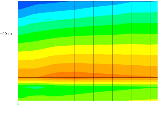
For all the loading cases of both bridges, and for all girders, five maximum stress zones had been observed: (i) two zones are located near the midspan close to the top surface (compression zone) and at the bottom surface (tensile zone), (ii) two other zones near the support section, the top zone with tensile stresses or low compressive stresses, and the bottom zone with compressive stresses, and (iii) the fifth zone appears as a stress concentration spot that covers the bottom transition area of girder web and bottom flange. The first four maximum stress zones are captured by the simplified analysis approach, where it can provide an approximate estimate to the stresses. The support-top-zone is small and covers 1-3% of the span length and half to full top flange thickness. The support-bottom-zone is covering 3% to 7% of the span length and again half to full bottom flange thickness. The fifth zone is not captured by the simplified analysis approach. It is located at 2-3% of the span length in the longitudinal direction and covers 1-4% of the span length. In most of the cases, this zone is subjected to higher compressive stresses than that of the
support-bottom-zone. Fig. 3 shows this zone for the 45 m span UHPC Bridge and for CPCI 1200 at SLS. It has also been observed that this zone expands in the longitudinal direction up to the support section as the girder section is becoming smaller, e.g. from CPCI 1200 to CPCI 900 for the UHPC bridge, and as the span length is increased. Experimental tests(13) have identified a crush failure in the same zone.
Span=45 m
Fig. 3. SLS Stress Concentration Zone at Flange-Web Region Near Support of UHPC Bridge with CPCI 1200 Girders
In general, the results show that the maximum stresses for the case of three-lane loading are less critical than the extreme stresses due to the case of two lane loading. This can be observed by comparing Fig. 4-a with Fig. 6-a, Fig. 4-b with Fig. 6-b, Fig. 5-a with Fig. 7-a, Fig. 5-b with Fig. 7-b. Since the same girder type is used for both loading cases, then the two-lane loading case is governing the design.
The compressive stresses are generally low even in the extreme compressive zones and far below the allowable limit of 0 for both HPC and UHPC bridges at SLS. Figs. 4(b) and
(5a) show maximum compressive stress of 0 and ' for the bottom support section
and bottom midspan section of the 45 m span UHPC bridge under SLS-two lane loading.
While Fig. 6-b and Fig. 7-a show maximum compressive stress of and for the
' 6 . fc ' 45 . fc 0.17fc ' 38 . 0 fc 0.16fc'
same sections at SLS under three-lane loading. Lower compressive stress levels in similar sections have been observed for the shorter span lengths. Fig. 10-b and Fig.11-a show
maximum compressive stress of 0 and ' for the bottom support section and
bottom midspan section of the 35m span UHPC bridge at SLS under –two-lane loading. For the 40 m span length, Fig. 12-b and Fig. 13(a) shows maximum compressive stress of
and for the bottom support section and bottom midspan section at SLS under
two-lane loading, respectively. At ULS, the compressive stress could reach to 0 as
shown in Fig.8(b). ' 30 . fc 0.11fc ' 39 . 0 fc ' 65fc ps ρ ' 15 . 0 fc ps ρ ' 5 . 0 fc .
For the HPC bridge, the stresses in support zones and the top compressive midspan zone are sensitive to a change in and exhibit a nonlinear relationship in general. This is shown in Figures 4(a), 4(b), 5(a)a, . 6(a) 6(b) , (8a) , 8(b) , (10a) and (12a). The stresses at the top support zone of the HPC bridge could easily fluctuate between compression and tension following a slight change of as shown in Figures 4(a), (10a) and (12a). For the UHPC bridge, the compressive stresses in all maximum stress zones vary quasi-linearly with as shown in Figures (4b), (5a), (6b), (7a), (8b), and (9a).. The rate of change in the stresses for CPCI 1200 is usually equal or less than that of the CPCI 900 (Fig. 4-b, Fig. 6-b, Fig. 8-b, Fig. 10-8-b, Fig. 12-b) except for the top support zone where it is higher than that of the CPCI 900 (Fig. 4-a, Fig. 6-a, Fig. 8-a, Fig. 10-a, Fig. 12-a). It has been also observed that the rate of change in the extreme compressive or tensile stresses in the UHPC bridge girder increases with increasing , i.e. the slope of the linear relationship is increased (e.g. compare Fig. 10-b and Fig. 11-b to Fig. 4-b and Fig. 5-b, respectively).
ps ρ ps ρ ps ρ
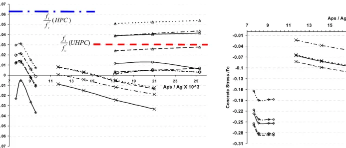
The extreme tensile stresses at the bottom of the girder midspan exhibit linear relationships
with (See Fig.5-b, Fig. 7-b, Fig. 9-b, Fig. 11-b and Fig. 13-b). The thick dashed
horizontal lines in the related figures identify the allowable tensile stresses for HPC and UHPC bridges. If the girders are designed for no-cracking criterion under service loads, the midspan tension zone would control the design in the cases of two-tendon-groups profile rather than the “bottom-only prestressing steel” tendons profile. However, for the CPCI 900 I-girder with only bottom prestressing steel straight tendons, the extreme centerline tensile stresses are decreased and the extreme tensile stresses at the support section are increased and start controlling the design in this case (see Figs. 4-a and 5-b, for example). The extreme compressive and tensile stresses in the case of “bottom-only prestressing steel” are higher than those corresponding to other examined profiles with “top to bottom and bottom prestressing steel” as shown Fig. 4-b and Fig. 6-b for example. In addition, the stresses at the deck slab specifically at the support section are highly increased in the case of “bottom-only prestressing steel”. These preliminary trials in the bridge design and stress analysis of this study show that a high eccentricity of the conventional deflected tendons at the support section is needed for the UHPC girders, however, the eccentricity is not studied as a design parameter here and left for future investigations.
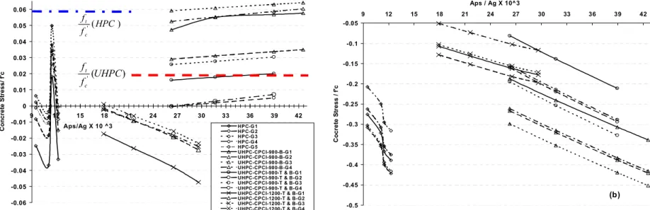
-0.06 -0.05 -0.04 -0.03 -0.02 -0.01 0 0.01 0.02 0.03 0.04 0.05 0.06 9 12 15 18 21 24 27 30 33 36 39 42 Aps/Ag X 10 ^3 Co n c ret e S tress/ f 'c HPC-G 1 HPC-G 2 HPC-G 3 HPC-G 4 HPC-G 5 UHPC-CPCI-900-B-G 1 UHPC-CPCI-900-B-G 2 UHPC-CPCI-900-B-G 3 UHPC-CPCI-900-B-G 4 UHPC-CPCI-900-T & B-G 1 UHPC-CPCI-900-T & B-G 2 UHPC-CPCI-900-T & B-G 3 UHPC-CPCI-900-T & B-G 4 UHPC-CPCI-1200-T & B-G1 UHPC-CPCI-1200-T & B-G2 UHPC-CPCI-1200-T & B-G3 UHPC-CPCI-1200-T & B-G4 ) ( ' UHPC f f c t ) ( ' HPC f f c t -0.5 -0.45 -0.4 -0.35 -0.3 -0.25 -0.2 -0.15 -0.1 -0.05 9 12 15 18 21 24 27 30 33 36 39 42 Aps / Ag X 10^3 Co cret e S tress / f 'c (b)
Fig. 4. SLS Stresses at Support of 2Design-Lanes UHPC and HPC Girders with Span of 45m: (a) top fiber; (b) bottom fiber.
-0.17 -0.15 -0.13 -0.11 -0.09 -0.07 9 14 19 24 29 34 39 Aps / Ag X 10^3 C o cr et e S tr ess / f 'c (a) -0.06 -0.04 -0.02 0 0.02 0.04 0.06 0.08 0.1 0.12 0.14 0.16 0.18 0.2 0.22 0.24 9 12 15 18 21 24 27 30 33 36 39 42 Aps /Ag X 10 ^3 C o cr et e st ress/ f 'c (b)
- 0 . 0 5 - 0 . 0 4 - 0 . 0 3 - 0 . 0 2 - 0 . 0 1 0 0 . 0 1 0 . 0 2 0 . 0 3 0 . 0 4 0 . 0 5 0 . 0 6 0 . 0 7 0 . 0 8 9 1 4 1 9 2 4 2 9 3 4 3 9 A p s / A g X 1 0 ^ 3 C oncr e te S tr ess / f 'c ( a ) -0.4 -0.37 -0.34 -0.31 -0.28 -0.25 -0.22 -0.19 -0.16 -0.13 -0.1 -0.07 -0.04 9 14 19 24 29 34 39 Aps /Ag X 10^3 Co n c re te S tr ess / f 'c (b)
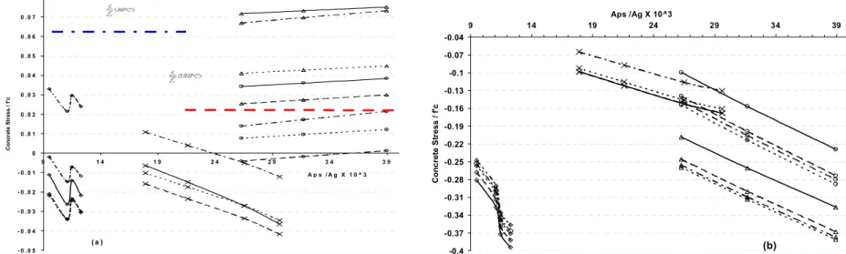
Fig. 6. SLS Stresses at Support of 3 Design-Lanes UHPC and HPC Girders with Span of 45m: (a)top fiber; (b) bottom fiber
-0.17 -0.15 -0.13 -0.11 -0.09 -0.07 -0.05 9 14 19 24 29 34 39 Aps / Ag X 10^3 C o n c re te S tr ess / f’ c (a) -0.1 2 -0.1 -0.0 8 -0.0 6 -0.0 4 -0.0 2 0 0.0 2 0.0 4 0.0 6 0.0 8 0.1 0.1 2 0.1 4 0.1 6 0.1 8 9 12 15 18 21 24 27 30 33 3 6 39 Aps / Ag X 1 0^3 C o n c re te S tr ess / f' c (b)
-0.04 -0.02 0 0.02 0.04 0.06 0.08 0.1 9 12 15 18 21 24 27 30 33 36 39 42 Aps/Ag X 10 ^3 Co n c re te S tr ess/ f 'c (a) -0.45 -0.4 -0.35 -0.3 -0.25 -0.2 -0.15 -0.1 -0.05 0 0.05 9 12 15 18 21 24 27 30 33 36 39 42 Aps / Ag X 10^3 Co n c re te S tr ess / f 'c (b)
Fig. 8. ULS Stresses at Support of 2Design-Lanes UHPC and HPC Girders with Span of 45m: (a) top fiber; (b) bottom fiber.
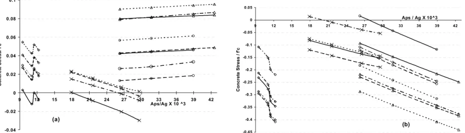
-0.21 -0.19 -0.17 -0.15 -0.13 -0.11 -0.09 -0.07 9 14 19 24 29 34 39 Aps / Ag X 10^3 C o n c re te S tr ess / f 'c (a) 0.05 0.1 0.15 0.2 0.25 0.3 0.35 0.4 0.45 0.5 9 12 15 18 21 24 27 30 33 36 39 42 Aps /Ag X 10 ^3 C o n c re test ress/ f 'c (b) Fig. 9. ULS Stresses at Midspan of 2 Design-Lanes UHPC and HPC Girders with Span of 45m: (a) top fiber; (b) bottom fiber
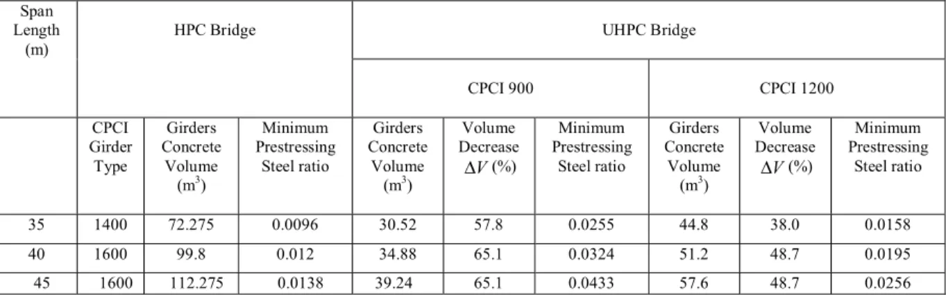
-0.07 -0.06 -0.05 -0.04 -0.03 -0.02 -0.01 0 0.01 0.02 0.03 0.04 0.05 0.06 0.07 7 9 11 13 15 17 19 21 23 25 Aps / Ag X 10^3 C o n cr et e S tr ess / f 'c ) ( ' HPC f f c t ) ( ' UHPC f f c t -0.31 -0.28 -0.25 -0.22 -0.19 -0.16 -0.13 -0.1 -0.07 -0.04 -0.01 7 9 11 13 15 17 19 21 23 25 Aps / Ag X 10^3 Co n c re te S tr ess /f 'c (b)
Fig. 10. SLS Stresses at Support of 2Design-Lanes UHPC and HPC Girders with Span of 35m: (a) top fiber; (b) bottom fiber.
-0.11 -0.1 -0.09 -0.08 -0.07 -0.06 -0.05 -0.04 7 12 17 22 Aps / Ag X 10^3 C o n c re te S tr ess / f 'c (a) -0.1 -0.08 -0.06 -0.04 -0.02 0 0.02 0.04 0.06 0.08 0.1 0.12 0.14 0.16 7 9 11 13 15 17 19 21 23 25 Aps / Ag X 10^ 3 Co n c ret e S tress / f 'c ) ( ' HPC f f c t ) ( ' UHPC f f c t
-0.06 -0.045 -0.03 -0.015 0 0.015 0.03 0.045 0.06 7 12 17 22 27 32 37 Aps / Ag X 10^3 C o n cr et e S tr ess / f 'c ) ( ' HPC f f c t ) ( ' UHPC f f c t -0.42 -0.37 -0.32 -0.27 -0.22 -0.17 -0.12 -0.07 -0.02 7 12 17 22 27 32 37 Aps/ Ag X 10^3 C o n c re te St ress / f 'c
Fig. 12. SLS Stresses at Support of 2 Design-Lanes UHPC and HPC Girders with Span of 40 m: (a) top fiber; (b) bottom fiber.
-0.15 -0.14 -0.13 -0.12 -0.11 -0.1 -0.09 -0.08 -0.07 -0.06 -0.05 7 12 17 22 27 32 37 Aps / Ag X 10^3 Co n cret e S tress / f 'c (a) -0 .0 6 -0.0 4 5 -0 .0 3 -0.0 1 5 0 0.0 1 5 0 .0 3 0.0 4 5 0 .0 6 0.0 7 5 0 .0 9 0.1 0 5 0 .1 2 0.1 3 5 0 .1 5 0.1 6 5 0 .1 8 7 12 1 7 22 27 3 2 37 Aps/Ag X 10^3 Co n c ret e S tress / f 'c ) ( ' HPC f f c t ) ( ' UHPC f f c t
A comparison of the results for CPCI 1200 and CPCI 900 for the case of dual tendon groups (i.e. straight bottom and conventional deflected strand pattern groups) (see Fig. 4 to Fig. 13) shows that the stresses in the CPCI 1200 girder are low and the section represents a conservative choice for the investigated spans (35 m to 45 m). On the other hand, all the
compressive stresses in the CPCI 900 girder are below for SLS and below for
ULS, while the tensile stress at the bottom fiber of the mid-span is high and controlling the design (See Fig. 5-b, Fig 11-b and Fig 13-b for example). Consequently, the prestressing area ratio needed to match the non-cracking requirement is relatively high. The comparison between the two sections yields two major conclusions: (i) the optimum section could be somewhat larger the than CPCI-900 and much smaller than CPCI 1200, (ii) increasing the ratio between the section moment of inertia to the section area would improve the girder design without adding sectional area and thus increasing the concrete weight.
'
45 .
0 fc 0.65fc'
COMPARISON OF MATERIALS CONSUMPTION IN UHPC AND HPC BRIDGES
In this section, a comparison between the concrete and the prestressing steel consumption in the designed UHPC and HPC bridges is made. It is clear that a reduction in the weight of the superstructure will lead to a reduced size of the substructure (piers and abutments) and foundations and reduced overall cost of the bridge . Furthermore, a reduction in the cement consumption will lead to great environmental benefits through the reduction of greenhouse gas emission (GHG) since the production of 1 ton cement leads to approximately 1 ton of GHG emissions14.
Since the deck slab thickness is assumed to be the same for both HPC and UHPC bridges; hence the comparison of the concrete volume is related to the total volume of the girders of each type bridge. Table 2 shows the concrete volume for the HPC and UHPC bridges for the three studied spans of 35 m, 40 m, and 45 m and for different CPCI sections. Table 2 shows that UHPC enables a considerable reduction in the concrete volume of up to 48.7% for the CPCI 1200 and 65% for CPCI 900.
Table 2 Comparison of HPC and UHPC Girder Bridges
UHPC Bridge Span Length (m) HPC Bridge CPCI 900 CPCI 1200 CPCI Girder Type Girders Concrete Volume (m3) Minimum Prestressing Steel ratio Girders Concrete Volume (m3) Volume Decrease V ∆ (%) Minimum Prestressing Steel ratio Girders Concrete Volume (m3) Volume Decrease V ∆ (%) Minimum Prestressing Steel ratio 35 1400 72.275 0.0096 30.52 57.8 0.0255 44.8 38.0 0.0158 40 1600 99.8 0.012 34.88 65.1 0.0324 51.2 48.7 0.0195 45 1600 112.275 0.0138 39.24 65.1 0.0433 57.6 48.7 0.0256
Table 2 also shows the minimum prestressing steel area ratio required for no crack design. It is found that CPCI 900 requires approximately 1.7 times more prestressing than CPCI 1200. The prestressing steel area required for CPCI 900 section is only 14% higher than that for the CPCI 1200. On the other hand, the required prestressing for the CPCI 900 is approximately 2.7 times that required for the CPCI 1400 and 3.2 times that for CPCI 1600, however the CPCI 1400 and CPCI 1600 cross sectional areas are 1.9 and 2.3 times the cross sectional area of CPCI 900, respectively. Hence, the prestressing steel area required for CPCI 900 section is 42% and 39% higher than that for the CPCI 1400 and CPCI 1600, respectively.
CONCLUSIONS
The use of UHPC in precast/prestressed concrete girders enables significant reductions in the number of girders and girder size. It also enables longer spans without further increase in the girder size. This study shows that UHPC yields a considerable reduction in the concrete volume of up to 48.7% and 65% for CPCI 1200 and CPCI 900 girders, respectively. The total prestressing steel area required for UHPC - CPCI 900 section is 42% and 39% higher than that for the CPCI 1400 and CPCI 1600, respectively for the span lengths 35 m, 40 m and 45 m. On the other hand, the minimum prestressing steel area required for the UHPC-CPCI 900 is only 14% higher than that for the UHPC-CPCI 1200 while the reduction of the concrete volume is about 33%.
The 3-D finite element model shows that the stress distributions in the UHPC bridge girders yield patterns similar to those of the HPC bridge. The stress distribution in the girder and the regions of stress concentration do not agree perfectly with the results obtained using the simplified load distribution method of CHBDC-06. Further investigations are needed to develop a simplified approach capable to accurately capture the extreme stresses in UHPC bridges.
The compressive stresses in the UHPC bridge girders are generally much lower than the allowable limit at SLS and reaches 65% of the compressive strength at ULS. However, the extreme tensile stresses is controlling the design and govern the prestressing steel area ratio. On the other hand, the dual tendons profile (with the straight and the conventional deflected tendons) yields a better stress distribution in the girder and reduces the tensile stresses in the top flange and deck slab at the support section.
The UHPC girder stresses show linear relationships with the prestressing steel area and this could lead to a simple preliminary design formula for the precast prestressed UHPC concrete girders. On the other hand a comparison between the two UHPC examined sections shows that an optimum section that is between CPCI-900 and CPCI 1200 can be achieved by increasing the ratio between the section moment of inertia to the section area. This would improve the girder capacity without adding higher sectional area and hence higher concrete weight.
REFERENCES
1. Lounis, Z., and Cohn, M.Z., “Optimization of Precast Prestressed Bridge Girder Systems”, PCI Journal, V. 38, No. 4, 1993, pp 60-77.
2. Lounis, Z., and Mirza, M.S., “High Strength Concrete in Spliced Prestressed Concrete Bridge girders.” Proc. of PCI/FHWA International Symp. on High Performance Concrete, New Orleans, 1997, pp.39-59.
3. Tang, Man-Chung, “High-Performance Concrete – Past, Present and Future”, Proceedings of the International Symposium on Ultra High Performance Concrete, Kassel, Germany, September 13-15, 2004, pp.3-9.
4. Rahman, S., Molyneaux, T., and Patnaikuni, I., “Ultra high performance concrete, recent applications and research”, Australian Journal of Civil Engineering, V. 2, No. 1, 2005, pp.13-20.
5. Acker, P., and Behloul, M., “ Ductal® Technology: A Large Spectrum of Properties, A Wide Range of Application”, Proceedings of the International Symposium on Ultra High Performance Concrete, Kassel, Germany, September 13-15, 2004, pp.11-23.
6. Buitelaar, P., “Heavy Reinforced Ultra High Performance Concrete”, Proceedings of the International Symposium on Ultra High Performance Concrete, Kassel, Germany, September 13-15, 2004, pp.25-35.
7. Hajar, Z., Lecointre, D., Simon, A., and Petitjean, J. “Design and Construction of the World First Ultra-High Performance Concrete Road Bridges”, Proceedings of the International Symposium on Ultra High Performance Concrete, Kassel, Germany, September 13-15, 2004, pp.39-48.
8. Meda, A., and Rosati, G., “Design and Construction of a Bridge in Very High Performance Fiber-Reinforced Concrete”, Journal of Bridge Engineering, Vol. 8, No. 5, 2003, pp.281-287.
9. Bierwagen, D., and Abu-Hawash, A., “Ultra High Performance Concrete Highway Bridge”, Proceedings of the 2005 Mid-Continent Transportation Research Symposium, Ames, Iowa, August 2005, pp.1-14.
10. AFGC Groupe de travail BFFUP, “Ultra High Performance Fiber-Reinforced Concretes: Interim Recommendations”, Scientific and Technical Committee, Association Française de Genie Civil, January 2002.
11. Canadian Prestressed Concrete Institute, “Design Manual, Precast and Prestressed Concrete”, Third Edition, 1996.
12. Canadian Standards Association, CAN/CSA-S6-06, “ Canadian Highway Bridge Design Code”, 2006
13. U.S. Department of Transportation, Federal Highway Administration, “ Structural Behavior of Ultra-High Performance Concrete Prestressed I-Girders”, Publication No. FHWA-HRT-06-115, August 2006.
14. Daigle, L., and Lounis, Z., “Life Cycle Cost Analysis of HPC Bridges Considering their Environmental Impact”, Proc. of INFRA 2006, Quebec City, pp. 1-17.
APPENDIX
Unit conversion factors
To Convert From (SI) to (US) divide by Length: meter (m) millimeter (mm) foot (ft) inch (in.) 0.3048 25.4 Area
square millimeter (mm2) square inch (in.2) 645.2
section modulus (mm3) in.3 16,387
Moment of inertia (mm4) in.4 416,231
Stress:
mega Pascal (MPa) mega Pascal (MPa)
kips/square inch (ksi) pounds/square inch (psi)
6.895 0.006895
Mass per volume