Publisher’s version / Version de l'éditeur:
Proceedings of the IEEE International Ultrasonics Symposium, 2009, 2009-09-01
READ THESE TERMS AND CONDITIONS CAREFULLY BEFORE USING THIS WEBSITE. https://nrc-publications.canada.ca/eng/copyright
Vous avez des questions? Nous pouvons vous aider. Pour communiquer directement avec un auteur, consultez la première page de la revue dans laquelle son article a été publié afin de trouver ses coordonnées. Si vous n’arrivez pas à les repérer, communiquez avec nous à [email protected].
Questions? Contact the NRC Publications Archive team at
[email protected]. If you wish to email the authors directly, please see the first page of the publication for their contact information.
NRC Publications Archive
Archives des publications du CNRC
This publication could be one of several versions: author’s original, accepted manuscript or the publisher’s version. / La version de cette publication peut être l’une des suivantes : la version prépublication de l’auteur, la version acceptée du manuscrit ou la version de l’éditeur.
Access and use of this website and the material on it are subject to the Terms and Conditions set forth at
High temperature guided acoustic wave transducers using mechanical
gratings
Wu, K. -T.; Liu, W. -L.; Kobayashi, M.; Jen, C.-K.; Ono, Y.; Takeuchi, M.
https://publications-cnrc.canada.ca/fra/droits
L’accès à ce site Web et l’utilisation de son contenu sont assujettis aux conditions présentées dans le site LISEZ CES CONDITIONS ATTENTIVEMENT AVANT D’UTILISER CE SITE WEB.
NRC Publications Record / Notice d'Archives des publications de CNRC:
https://nrc-publications.canada.ca/eng/view/object/?id=9cc2ac27-6514-427a-99a5-33ae9279009d https://publications-cnrc.canada.ca/fra/voir/objet/?id=9cc2ac27-6514-427a-99a5-33ae9279009d
High Temperature Guided Acoustic Wave
Transducers Using Mechanical Gratings
K.-T. Wu1, W.-L. Liu1, M. Kobayashi2, C.-K. Jen2, Y. Ono3, M. Takeuchi 4
1. Department of Electrical and Computer Eng., McGill University, Montreal, Quebec, Canada H3A 2A7 2. Industrial Materials Institute, National Research Council Canada, Boucherville, Quebec, Canada J4B 6Y4 3. Department of Systems and Computer Eng., Carleton University, Ottawa, Ontario, Canada K1S 5B6 4. Department of Intelligent Information Systems, Tamagawa University, Tokyo, Japan 194-8610
Abstract— Integrated and flexible guided acoustic wave
transducers have been made using line shape mechanical gratings together with sol-gel fabricated integrated ultrasonic transducers at the opposite side. They can be used to generate and receive guided surface and plate acoustic waves and to operate up to 150°C. Preliminary results show the potentials of them for non-destructive evaluation and structural health monitoring applications.
Keywords- flexible ultrasonic transducer, mechanical gratings, array, high temperature, structural health monitoring, NDE
I. INTRODUCTION
Guided acoustic waves are of attraction for structural health monitoring (SHM) and nondestructive evaluation (NDE) applications because they may inspect parts or structures, in particular, made of metals of a large area within a short time period using a few ultrasonic transducers (UTs) [1, 2]. For aerospace industry such SHM and NDE may require that the UTs operate from -80°C to 100°C. In other areas the operation temperatures may be required to be higher [3, 4]. Guided waves may be surface (SAW) or plate acoustic waves (PAW).
Mechanical line-shape gratings have been used to effectively convert bulk longitudinal (L) waves to surface acoustic waves (SAW) [5, 6]. The main applications were aimed at high frequency SAW filters. However, in the last decade such gratings have been also applied as mode converters from L to SAW or PAWs and as reflectors for the touch screen panels (or displays) made of glass substrates [7-9]. Such touch screen panels are widely used at many major transportation industry stations, department stores, different institutions, etc and become a convenient tool involved in human daily living. The main motivation of this research is to regard the touch display panel as an approach for SHM or NDE of a large part, however, the panel is made of metals. The analogy is that any defect is initiated or propagated within this panel the guided SAWs or PAWs propagating in the entire panel can detect the defect location and even the size. In this investigation thin and light weight integrated and flexible guided acoustic wave transducers involving the use of line-shape mechanical gratings only as mode converters are studied for the SHM and NDE application at temperatures up to 150°C.
II. TRANSDUCER FABRICATION
The line mechanical gratings are machined with a line width of 0.3 mm, an aperture of 10 mm and different depths
and number of gratings using electrical discharge machining (EDM). The gratings will be used to convert L waves into SAWs [6, 7] and PAWs depending on the substrate thicknesses. Piezoelectric lead-zirconate-titanate composite (PZT-c) films served as L wave integrated UTs (IUTs) were made by a sol-gel sprayed technique [4, 10] onto the opposite surface of the metallic substrate having the mechanically gratings. The merit of this approach is that IUT can be at the internal surface of a structure and mechanical gratings at the external surface. If the substrates are 75µm thick membranes, then it is a flexible UT (FUT). FUTs may be attached or bonded to metal parts even with curved surfaces and used for guided wave NDE and SHM.
The sol-gel spray fabrication method of the PZT-c film consists of six main steps [4, 11]: (1) preparing a high dielectric constant PZT solution, (2) ball milling of piezoelectric PZT powders to a submicron size, (3) film spraying using slurries from steps (1) and (2) to produce a layer of slurry film onto thin metal membrane substrates, (4) heat treatment to produce a solid PZT-c film on the metal substrates, (5) corona poling to obtain piezoelectricity of the composite ceramic film, and (6) electrode painting of electrical connections. Steps (3) and (4) are performed multiple times to produce the proper film thickness for optimal IUT and FUT ultrasonic operating frequencies. One main merit of the sol-gel spray technique is to offer the on-site fabrication capability for IUTs. Also on-site installation ability using gluing and brazing [12] can be provided by FUTs which may be mass produced in the laboratory.
III. RESULTS AND DISCUSSIONS
In this section the experimental and numerical simulation results of SAW and PAW generation and receiving using line mechanical gratings and mode conversion from L waves to SAWs and PAWs, respectively will be presented up to 150°C. A. Integrated guided SAW transducers on a SS plate
In order to show the capability of integrated guided SAW transducer line-shape mechanical gratings as shown in Fig. 1 with a line interval of 0.6 mm, a width of 0.3 mm, a depth of 0.06 mm, an aperture of 10 mm and 6 gratings have been made onto the grating side of 10 mm thick SS plate. According to [5] the optimum depth of the grating is 0.6 mm, but here 0.06 mm is chosen for easy machining. The gratings may be made to have symmetrical or anti-symmetrical shape to increase the
efficiency of mode conversion and directivity [5]. PZT-c films have been also made as IUTs at the direct opposite side of these gratings and their thicknesses are about 82 µm thick which corresponds to a center frequency of an L wave of 7.9 MHz with a 6 dB bandwidth of 4 MHz. The dimensions of the top electrodes are about 9 mm by 3.5 mm which covers about 6 gratings area.
10mm
10mm thick stainless steel plate
IUTL R IUTR T 10mm Front View Back View 100mm 200mm 50 mm 3.3mm
Figure 1. Line-shape mechanical gratings with a line interval of 0.6 mm, a width of 0.3 mm, a depth of 0.06 mm, an aperture of 10 mm and 6 gratings have been made onto a 10 mm thick SS plate. PZT-c films with 82 µm thick were deposited on the opposite side of gratings directly.
10 20 30 40 50
Amplitude (arb. unit)
Time Delay (µs) RT’R T” RT (a) 10 20 30 40 50
Amplitude (arb. unit)
Time Delay (µs) RT’R
T”
RT
(b)
Figure 2. Ultrasonic performance of the IUTs shown in Fig. 1 and operated in transmission mode (a) at room temperature (b) at 150°C.
At room temperature the measured VL and VS of this SS
substrate are 6056 m/s and 3328 m/s, respectively. Using these data and the calculated SAW is 3022 m/s with 5 MHz of center frequency in this design of 0.6 mm wide line interval grating. Fig 2 shows the measured ultrasonic signals in transmission mode in time domain of the measurement (a) at room temperature and (b) at 150°C. The data shown in Fig. 2(a) and 2(b) were filtered with a band pass filter centered at 5 MHz. RT
is the first SAW arrival signal. Because of the 10 mm thick SS plate, bulk L waves generated and received by the IUT also traverse back and forth from the top and bottom surfaces of this plate. The large echoes RT’ and RT” follow the echo RT come
from such reverberation with a time delay of about 3.3 µs. Such echoes RT’ and RT” can be significantly reduced if the incident
L waves toward the line gratings is at an inclined angle or the SS plate has a non-parallel top and bottom surfaces. At room temperature the measured SAW is 3012 m/s which agrees well with the theoretically calculated value of 3022 m/s. At 150°C, as shown in Fig. 2(b), the measured SAW velocity is about 2905m/s. Fig. 3 shows the numerical simulated results of this configuration at room temperature using Wave3000 commercial available software which agree well with the experimental result shown in Fig. 2(a). In addition the center frequency of the received signal in Fig. 3 is also around 5 MHz.
Figs. 2(a) and 2(b) provide the possibility of high temperature guided SAW generation and receiving for 150°C NDE and SHM.
10 20 30 40 50
Amplitude (arb. unit)
Time Delay (µs) RT’R
T”
RT
Figure 3. Numerically calculated SAW signals in time domain at room temperature in the SS plate as shown in Fig. 1.
B. Flexible guided plate acoustic wave transducers on 75 µm stainless steel membranes
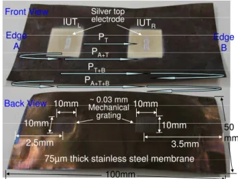
Since the grating has been approved to be able to generate and receive SAW at room temperature [5, 6] and at 150°C as demonstrated above, it is also of interest to study whether flexible guided PAW grating transducer can be developed if the above 10 mm thick SS plate is replaced with a 75 µm SS membrane. The IUT can be still deposited at the opposite site of the line grating. Using SS membrane high temperature high efficient bulk L wave FUT were reported in [4, 12]. For guided PAW grating FUTs line-shape mechanical gratings with a line interval of 0.6 mm, a width of 0.3 mm, a depth of ~0.03 mm, an aperture of 10 mm and 17 gratings have been made onto SS membranes of 75 µm thick by the EDM. The depth of ~0.03 mm of the grating is almost a half of the membrane thickness. Again these mechanical gratings are made in symmetrical shape because of convenience in machining. PZT-c films have been made as IUTs at the direct opposite side of these gratings and their thicknesses are about 62 µm thick which corresponds to a center frequency of an L wave of 15 MHz. In this investigation such transducers are named as PAW grating FUTs. 50 mm 100mm 10mm 10mm 10mm 10mm 2.5mm 3.5mm
75µm thick stainless steel membrane IUTL Front View Back View Edge A Edge B IUTR PT PA+T PT+B PA+T+B Silver top electrode ~ 0.03 mm Mechanical grating
Figure 4. A 75 µm thick SS membrane with two 62 µm thick PZT-c films. Line-shape mechanical gratings with a line interval of 0.6 mm, a width of 0.3 mm, a depth of ~0.03 mm, an aperture of 10 mm and 17 gratings have been made onto the SS membrane.
At first, ultrasonic measurements in transmission mode were carried out. In Fig. 4 IUTL was used as the transmitting
IUT and IUTR as the receiver. The ultrasonic signals obtained
in this transmission configuration at room temperature with the IUT top electrode which covers 3, 7 and 10 line-grating areas are shown in Figs. 5, 6 and 7, respectively. In theses figures the time and frequency domain signals are given in (a) and (b), respectively. As expected [5] the higher number of line gratings provides narrower bandwidth of the PAWs. The propagation paths of echoes PT, PA+T, PT+B, and PA+T+B, are indicated in
Fig.4. Because the edges of the SS membrane serve as PAW reflectors, for example, the propagation path of echo PA+T starts
from the IUTL together with the mechanical grating to the Edge
A and reflected and received by IUTR together with the
mechanical grating. It also means that pulse-echo capabilities of such PAW grating FUT transducers have been demonstrated as well. From the time delays of PT, PA+T, PT+B, and PA+T+B the
velocity of the PAW is 4870 m/s which indicates the first symmetrical mode S0 [13, 14] for the SS membrane used. The
signal-to-noise ratio (SNR) of the received signal PT in Figs.
5(a), 6(a) and 7(a) is 17 dB, 16.6 dB and 8.7 dB, respectively. The anti-symmetrical mode propagation, in particular, the first A0 was also expected to be generated and received by such
PAW grating FUTs, however it was weak. Their arrival time comes much later because of the slow velocity and interfered by the later arriving of multiple echoes of the symmetrical mode traversing back and forth within the SS grating FUT membrane. It will be studied further in the future.
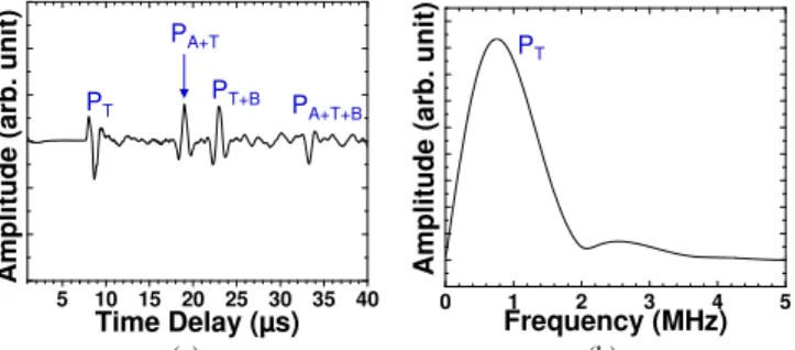
5 10 15 20 25 30 35 40 Ampli tude (a rb. uni t) Time Delay (µs) PT PA+T PT+B PA+T+B (a) 0 1 2 3 4 5 Ampl itude (a rb. u nit) Frequency (MHz) PT (b)
Figure 5. Ultrasonic performance of the IUTs shown in Fig. 4 and operated in transmission mode. 3 line-grating area is covered by silver top electrode.
5 10 15 20 25 30 35 40 Ampli tude (arb . u nit) Time Delay (µs) PT PA+T+B PA+T PT+B (a) 0 1 2 3 4 5 Am plitude (arb. u n it) Frequency (MHz) PT (b)
Figure 6. Ultrasonic performance of the IUTs shown in Fig. 4 and operated in transmission mode. 7 line-grating area is covered by silver top electrode.
In order to demonstrate the high temperature operation capability the whole PAW grating FUT membrane shown in Fig. 4 was directly put on top of a hot plate. Figure 8 shows the
ultrasonic signals obtained in transmission mode at 150°C with IUTs covering only 3 line-grating areas (~9 mm by 2 mm). The SNR of the received signal PT is 11.4 dB. The choice of 3
line-grating was because it gave the broader bandwidth of the received signal. 5 10 15 20 25 30 35 40 Amp litude (a rb. unit) Time Delay (µs) PT PA+T+B PA+T PT+B (a) PT 0 1 2 3 4 5
Amplitude (arb. unit)
Frequency (MHz)
(b)
Figure 7. Ultrasonic performance of the IUTs shown in Fig. 4 and operated in transmission mode. 10 line-grating area is covered by silver top electrode.
5 10 15 20 25 30 35 40 Am pli tu d e ( a rb . un it ) Time Delay (µs) PT PA+T+B PA+T PT+B
Figure 8. Ultrasonic performance of the IUTs shown in Fig. 4 and operated in transmission mode at 150°C. 3 line-grating area (~9 mm by 25 mm) is covered by silver top electrode.
C. Flexible guided plate acoustic wave transducers generate and receive PAW in a SS plate
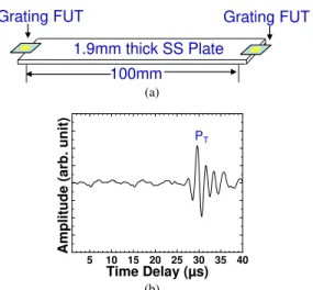
In order to demonstrate the potential of using grating FUT guided PAW transducer for SHM and NDE, the grating FUTs shown in Fig. 4 were cut into to two. Each part consisting of one grating with IUT below serves as guided PAW grating FUT. These two PAW grating FUTs were placed at the two ends of a 1.9 mm thick 100 mm long 50 mm wide SS plate as shown in Fig. 9(a), and their ultrasonic signal obtained in transmission mode is shown in Fig. 9(b). The SNR of the received signal is 20 dB. Then an artificial line defect with 1 mm depth and 1 mm width across the entire width 50 mm of the SS plate was made onto the middle of the SS plate, and the measured ultrasonic signal PT was 3.4 dB weaker than the
measured signal on SS plate without line defect. The line defects on plate can be detected by the amplitude change of ultrasonic signals, generated and detected by the grating FUTs, in transmission mode. The guided PAW grating FUT transducers could be attached or bounded onto plate structure like the bulk L wave FUTs reported in [12] for high temperature SHM or NDE.
ACKNOWLEDGMENT
Grating FUT Grating FUT 1.9mm thick SS Plate
100mm
Financial support from the Natural Sciences and Engineering Research Council is acknowledged.
(a) REFERENCES
[1] R.H. M.V. Gandhi and B.S. Thompson, B.S., Smart Materials and
Structures, Chapman & Hall, New York, 1992.
5 10 15 20 25 30 35 40
Amplitude (ar
b. unit)
Time Delay (µs)
PT
[2] J.-B. Ihn, and F.-K. Chang, “Ultrasonic Non-destructive Evaluation for Structure Health Monitoring: Built-in Diagnostics for Hot-spot Monitoring in Metallic and Composite Structures,” Chapter 9 in
Ultrasonic Nondestructive Evaluation Engineering and Biological Material Characterization, edited by T. Kundu, CRC Press, NY, 2004.
[3] S.P. Kelly, I. Atkinson, C. Gregory and K.J. Kirk, “On-line ultrasonic inspection at elevated temperatures,” Proc. IEEE Ultrasonics Symp., pp.904-908, 2007.
[4] M. Kobayashi, C.-K. Jen, J.F. Bussiere and K.-T. Wu, “High temperature integrated and flexible ultrasonic transducers for non-destructive testing,” NDT&E Int., vol.42, pp.157-161, 2009.
(b)
Figure 9. (a) Ultrasonic performance of PAW Grating FUTs shown in Fig. 4 are placed at the two end of a 1.9 mm thick stainless steel plate. (b) Ultrasonic performance of measurement setup in (a). The two grating FUTs were operated in transmission mode.
[5] R.F. Humphryes and E.A. Ash, “Acoustic bulk-surface-wave transducers,” Electron. Letts., vol.5, pp.175-6, 1969.
[6] A. Ronnekleiv, H.J. Shaw and J. Souquet, “Grating acoustic scanners,” Appl. Phys. Letts., vol. 28, pp.361-2, 1976.
[7] J. Kent and R. Adler, “Reflecting love waves by 90 degrees,” Proc. IEEE Ultrasonics Symp., pp.158-161, 2001.
IV. CONCULSIONS
Integrated and flexible guided acoustic wave transducers have been made using line shape mechanical gratings made by EDM together with sol-gel fabricated IUTs at the opposite side. IUTs served as bulk L wave transducers and these L waves were converted to SAW or PAW when they interacted with the line mechanical gratings depending on the substrate thickness. Guided SAW grating IUTs have been made and for such transducers IUTs are made directly under the line gratings in a 10 mm thick SS plate. The measured SAW velocity and frequency agreed well with the theoretical and numerical calculation. When the SS substrate is 75 µm thick which is flexible, the gratings together with IUTs served as guided PAW grating FUTs. The experimental results indicated that the more is the number of line gratings, the narrower is the bandwidth of the PAW. In this study symmetrical S0 mode was generated
and received. The detection of an artificial line defect created on a 100 mm long 50 mm wide SS plate was also demonstrated in a transmission mode using two guided PAW grating FUTs. These FUTs may be attached or bonded to parts even with curved surfaces. The preliminary results have indicated that they may be used for NDE and SHM purposes [12].
[8] M. Takeuchi, N. Fujita, P. Gomes, J. Kent and R. Adler, “Ultrasonic attenuation in acoustic touch panels,” Proc. IEEE Ultrasonic Symp, pp.1585-90, 2004.
[9] J. Kent, M. Takeuchi and G. Laux, “Robert Adler’s touchscreen inventions,” Proc. IEEE Ultrasonics Symp., pp.9-20, 2007.
[10] D. A. Barrow, T. E. Petroff, R. P. Tandon, and M. Sayer, “Characterization of thick lead zirconate titanate films fabricated using a new sol gel based process,” J. Appl. Phys., vol.81, pp. 876-881, 1997. [11] M. Kobayashi and C.-K. Jen, “Piezoelectric thick bismuth titanate/PZT
composite film transducers for smart NDE of metals,” Smart Materials and Structures, vol.13, pp.951-956, 2004.
[12] J.-L. Shih, M. Kobayashi and C.-K. Jen, “Flexible ultrasonic transducers for structural health monitoring of pipes at high temperatures,” Proc. IEEE Ultrasonics Symp., 2009 (this Proceeding).
[13] I.A. Viktorov, Rayleigh and Lamb waves, Plenum, New York, 1967. [14] K.-T. Wu, M. Kobayashi and C.-K. Jen, "Integrated high temperature
piezoelectric plate acoustic wave transducers," IEEE Trans. UFFC, vol.56, no.6, pp.1218-1224, June 2009.