Publisher’s version / Version de l'éditeur:
Journal of Testing and Evaluation, 34, May 3, pp. 241-245, 2006-05-01
READ THESE TERMS AND CONDITIONS CAREFULLY BEFORE USING THIS WEBSITE. https://nrc-publications.canada.ca/eng/copyright
Vous avez des questions? Nous pouvons vous aider. Pour communiquer directement avec un auteur, consultez la
première page de la revue dans laquelle son article a été publié afin de trouver ses coordonnées. Si vous n’arrivez pas à les repérer, communiquez avec nous à PublicationsArchive-ArchivesPublications@nrc-cnrc.gc.ca.
Questions? Contact the NRC Publications Archive team at
PublicationsArchive-ArchivesPublications@nrc-cnrc.gc.ca. If you wish to email the authors directly, please see the first page of the publication for their contact information.
Archives des publications du CNRC
This publication could be one of several versions: author’s original, accepted manuscript or the publisher’s version. / La version de cette publication peut être l’une des suivantes : la version prépublication de l’auteur, la version acceptée du manuscrit ou la version de l’éditeur.
Access and use of this website and the material on it are subject to the Terms and Conditions set forth at
Vapour permeances, air permeances and water absorption coefficients of building membranes
Kumaran, M. K.; Lackey, J. C.; Normandin, N.; van Reenen, D.
https://publications-cnrc.canada.ca/fra/droits
L’accès à ce site Web et l’utilisation de son contenu sont assujettis aux conditions présentées dans le site LISEZ CES CONDITIONS ATTENTIVEMENT AVANT D’UTILISER CE SITE WEB.
NRC Publications Record / Notice d'Archives des publications de CNRC: https://nrc-publications.canada.ca/eng/view/object/?id=19a42c72-f572-405f-8923-a670bb596a66 https://publications-cnrc.canada.ca/fra/voir/objet/?id=19a42c72-f572-405f-8923-a670bb596a66
Va por pe r m e a nc e s, a ir pe r m e a nc e s, a nd
w at e r a bsor pt ion c oe ffic ie nt s of building
m e m bra ne s
N R C C - 4 6 8 8 5
K u m a r a n , M . K . ; L a c k e y , J . C . ;
N o r m a n d i n , N . ; v a n R e e n e n , D .
A version of this paper is published in / Une version de ce document se trouve dans: Journal of Testing and Evaluation, v. 34, no. 3, May 2006, pp. 241-245
Mavinkal K. Kumaran1, John C. Lackey2, Nicole Normandin2, and David van Reenen2
VAPOR PERMEANCES, AIR PERMEANCES, AND WATER ABSORPTION COEFFICIENTS OF BUILDING MEMBRANES
ABSTRACT: Building membranes are integral parts of North American Buildings. Some are installed beneath commonly used exterior claddings, brick and stucco to reduce the risk of water infiltration into the wall systems. Others are used for controlling vapor diffusion though the envelope or as the airtight element of the air barrier system of the envelope. To determine the suitability of a membrane for its intended application, it is necessary to have reliable information on its inherent physical properties. This paper reports the water vapor permeance, the air permeance, and the water absorption coefficient for 18 building membranes that are found in North American markets today. These membranes include paper-based as well as polymer-based materials.
The properties reported here show that at the design stage most of the membranes can be considered as the airtight element of air barrier systems and as part of the second line of defense against rainwater penetration. The membranes provide a range of values for water vapor permeance and therefore open up opportunities for a designer to integrate innovative vapor diffusion control strategies for exterior walls and to prolong their service lives.
KEYWORDS: building membrane, water vapor permeance, water absorption coefficient, air permeance, vapour retarder, air barrier.
_____________________________________________________________________ 1
Principal Research Officer, 2 Technical Officer, Institute for Research in Construction, National Research Council of Canada, Ottawa, K1A 0R6, Canada
VAPOR PERMEANCES, AIR PERMEANCES AND WATER
ABSORPTION COEFFICIENTS OF BUILDING MEMBRANES
Mavinkal K. Kumaran, John C. Lackey, Nicole Normandin, and David van Reenen Building Envelope and Structure
Institute for Research in Construction N R C Canada
INTRODUCTION
Various types of polymeric and paper-based membranes frequently find applications in building envelopes. At a fraction of a millimetre thickness, the functions of these membranes may include strategies for vapor diffusion control, rainwater penetration control or control of air leakage. “6 mil” polyethylene sheet is commonly used for vapor diffusion control strategies for buildings in heating climates. Paper-based membranes, such as “10 min paper”, “30 min paper”, “60 min paper” and “# 15 felt” are used as part of the second line of defence underneath claddings for rainwater penetration control of light-frame buildings in all climatic conditions. Spun-bonded polyolefin membranes are used to wrap around exterior walls to function as the airtight element of air barrier systems as well as part of the second line of defense for rainwater penetration control. If one investigates the North American market one will find that the building membrane industry is at times as large as the insulation industry and the variety of membranes available in the market is great. Therefore building designers are free to choose these membranes and apply them creatively, as needed in the design of the building envelope. But how does one make the choice?
First one should look at the basic physical properties of the membrane in regard to the intended use. For example, information on vapor permeance helps one to assess the ability of the membrane to allow or resist the transfer of water vapor across it in the presence of a vapor pressure difference. Information on the air permeance helps assess the suitability of the membrane to be used as the airtight element of the air barrier system. The water absorption coefficient can be used to assess the membrane’s ability to resist water penetration. The information on the above three properties is not sufficient to establish the role of the membrane on the hygrothermal responses of the designed
building envelope. This is better handled through an analysis of heat, air, and moisture transport across the building envelope using advanced hygrothermal models[1,2]. Such an analysis helps to select the membrane to give the optimum performance of a given envelope component for a given geographical location and expected indoor climate. To carry out such an analysis, reliable information on the above three properties is needed. But, in the open literature such information is very sparse. To remedy this situation, properties of many building membranes were systematically determined at the Institute for Research in Construction using standard test procedures or their adaptations [3,10]. This paper reports the water vapor permeances for the full range of relative humidities, air permeances, if measurable, and the water absorption coefficients of 18 building membranes, one latex primer on gypsum board, and the primer in combination with a latex paint on gypsum board.
THE MEMBRANES
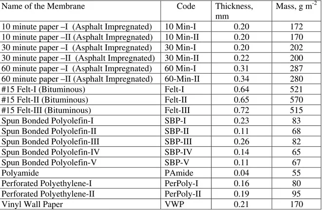
Commercial rolls of membranes were acquired for the investigation. The specifics of the 18 membranes are listed in Table 1.
Table 1. Generic names, mass per unit area and thickness of the membranes.
Name of the Membrane Code Thickness,
mm
Mass, g m-2 10 minute paper –I (Asphalt Impregnated) 10 Min-I 0.20 172 10 minute paper –II (Asphalt Impregnated) 10 Min-II 0.20 170 30 minute paper –I (Asphalt Impregnated) 30 Min-I 0.20 202 30 minute paper –II (Asphalt Impregnated) 30 Min-II 0.22 200 60 minute paper –I (Asphalt Impregnated) 60 Min-I 0.31 287 60 minute paper –II (Asphalt Impregnated) 60-Min-II 0.34 280
#15 Felt-I (Bituminous) Felt-I 0.64 521
#15 Felt-II (Bituminous) Felt-II 0.65 570
#15 Felt-III (Bituminous) Felt-III 0.72 515
Spun Bonded Polyolefin-I SBP-I 0.23 83
Spun Bonded Polyolefin-II SBP-II 0.11 68
Spun Bonded Polyolefin-III SBP-III 0.26 82
Spun Bonded Polyolefin-IV SBP-IV 0.14 65
Spun Bonded Polyolefin-V SBP-V 0.11 67
Polyamide PAmide 0.04 55
Perforated Polyethylene-I PerPoly-I 0.16 80
Perforated Polyethylene-II PerPoly-II 0.19 95
EXPERIMENTAL PROCEDURES AND RESULTS
All experimental procedures used in this investigation are based on well-established international standards or well-established procedures [3-6]. Various publications from the Institute have documented all these procedures elsewhere [7-10]. The principles of the methods are given below.
Water Vapor Permeance
The vapor diffusion equation is used directly to determine the water vapor permeance, δl of building membranes. The measurements are usually done under isothermal conditions. A test specimen of known area separates two environments that differ in relative humidity (RH). Then the rate of vapor flow across the specimen, under steady-state conditions (known RH’s as constant boundary conditions), is gravimetrically determined. From these data the water vapor permeance of the material is calculated as:
δl = Jv /(A⋅Δp) (1)
Where,
Jv = Water vapor flow rate across an area A
Δp = Difference in water vapor pressure across the specimen surfaces ASTM Standard, Test Methods for Water Vapor Transmission of Materials (E 96) [3], prescribes two specific cases of this procedure- a dry cup method that gives the permeance or permeability at a mean RH of 25 % and a wet cup method that gives the permeance or permeability at a mean RH of 75 %. A new CEN Standard 89 N 336 E is being developed in the European Union based on ISO standard 12572:2001. More recently a number of technical papers that deal with various technical aspects, limitations and analyses of the experimental data of these procedures have appeared in the literature [7,8,11,12].
Six circular test specimens, approximately 15 cm in diameter were used in these measurements, for each material. All measurements were done at 23 ± 0.3°C. Three
specimens of each material were used for a series of three dry cup (desiccant method) measurements with the chamber RH equal to approximately 50 %, 70 %, and 90 %. The other three specimens were used for a series of two wet cup (water method) measurements with the chamber RH equal to approximately 70 % and 90 %. At each test condition the RH was maintained within 0.5 % for the duration of each measurement. From the 15 results so obtained on each material the dependence of water vapor permeability on RH for that material was derived [8]. The results are listed in Table 2. Though each measurement on each test specimen yielded test data with less than 1 % uncertainty, the gross uncertainty in the derived values may be as high as 30 %, according to the statistical package TableCurve, used for the analyses. The inhomogenity of the products is the main reason for this rather large uncertainty in the derived values.
Air Permeance
Test specimens with known areas are positioned to separate two regions that differ in air pressure and the airflow rate at a steady state and the pressure differential across the specimen are recorded. From these data the air permeance, Ka is calculated as:
Ka = Ja/(A⋅Δp) (2)
Where,
Ja = Air flow rate across an area A
Δp = Difference in air pressure across the specimen surfaces
ASTM Standard, Standard Test Method for Airflow Resistance of Acoustical Materials (C 522) [4] prescribes a method based on this principle. Bomberg and Kumaran [9] have extended the method for general application to building materials.
The test specimens used in these measurements were identical to those used for the water vapor permeability measurements. Ranges of pressure differences up to 3 kPa were used in these measurements. Measurements were done in triplicate at each pressure differential. The results from these measurements are listed in Table 3. The uncertainties in the listed permeances can be as high as 100 %. This is partly due to inhomogenity of the materials and partly because of the very low and often immeasurable airflow rates even at a pressure difference of 3 kPa. In the immeasurable cases pressure decay
measurements at an over pressure of 100 kPa was used to estimate the order of magnitude of the permeances. All measurements were done at 22 ± 1°C.
Water Absorption Coefficient
One major surface of each test specimen is placed in contact with liquid water. The increase in mass as a result of moisture absorption is recorded as a function of time. Usually, during the initial part of the absorption process a plot of the mass increase against the square root of time is linear. The slope of the line divided by the area of the surface in contact with water is the water absorption coefficient. When this method is applied to membranes, the membranes are put in perfect hygric contact with a substrate such as oriented strand board (OSB) or gypsum board with the help of absorbent gypsum paste or kaolin paste. A new CEN Standard 89 N 370 E on the determination of water absorption coefficient is under development.
Four test specimens, 5 cm X 5 cm each, were prepared as follows. The membrane was attached to the major surface of a 5 cm X 5 cm OSB using a thin (less than 1 mm) layer of drywall compound and allowed to dry. The sides were then sealed using wax. Water was maintained at 22 ± 1 °C and allowed to touch the exposed surface of the membrane. The results from the water absorption measurements are listed in Table 4.
DISCUSSION
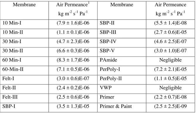
As mentioned in the introduction, the three properties reported here are most useful in choosing a membrane for a desired construction. The air permeances and water absorption coefficients reported in Tables 3 and 4 do not distinguish the 18 membranes that have been investigated to a great degree. The air permeances of all except SBP-I, SBP-III and the two perforated polyethylene membranes confirm that majority of the membranes available in North American market are close to or less than that of interior gypsum board (½ in.) with an air permeance of 3E-07 kg m-2 s-1 Pa-1. Gypsum board is being used as the airtight element in the air barrier system of envelopes. Therefore many of the membranes included in the present study can be considered to be the airtight element of a designed air barrier system.
The water absorption coefficients reported here suggests that the liquid diffusivity for these membranes fall in the range 10 -11 to 10 -13 m2 s-1[10]. This is
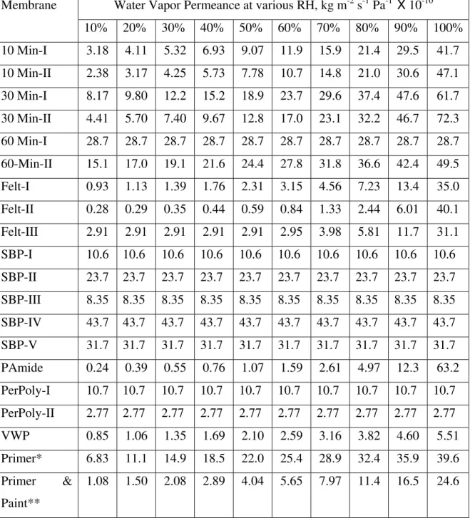
Table 2. Water vapor permeances of membranes at 23 ± 0.3 ºC.
Water Vapor Permeance at various RH, kg m-2 s-1 Pa-1 X 10⁻¹⁰ Membrane 10% 20% 30% 40% 50% 60% 70% 80% 90% 100% 10 Min-I 3.18 4.11 5.32 6.93 9.07 11.9 15.9 21.4 29.5 41.7 10 Min-II 2.38 3.17 4.25 5.73 7.78 10.7 14.8 21.0 30.6 47.1 30 Min-I 8.17 9.80 12.2 15.2 18.9 23.7 29.6 37.4 47.6 61.7 30 Min-II 4.41 5.70 7.40 9.67 12.8 17.0 23.1 32.2 46.7 72.3 60 Min-I 28.7 28.7 28.7 28.7 28.7 28.7 28.7 28.7 28.7 28.7 60-Min-II 15.1 17.0 19.1 21.6 24.4 27.8 31.8 36.6 42.4 49.5 Felt-I 0.93 1.13 1.39 1.76 2.31 3.15 4.56 7.23 13.4 35.0 Felt-II 0.28 0.29 0.35 0.44 0.59 0.84 1.33 2.44 6.01 40.1 Felt-III 2.91 2.91 2.91 2.91 2.91 2.95 3.98 5.81 11.7 31.1 SBP-I 10.6 10.6 10.6 10.6 10.6 10.6 10.6 10.6 10.6 10.6 SBP-II 23.7 23.7 23.7 23.7 23.7 23.7 23.7 23.7 23.7 23.7 SBP-III 8.35 8.35 8.35 8.35 8.35 8.35 8.35 8.35 8.35 8.35 SBP-IV 43.7 43.7 43.7 43.7 43.7 43.7 43.7 43.7 43.7 43.7 SBP-V 31.7 31.7 31.7 31.7 31.7 31.7 31.7 31.7 31.7 31.7 PAmide 0.24 0.39 0.55 0.76 1.07 1.59 2.61 4.97 12.3 63.2 PerPoly-I 10.7 10.7 10.7 10.7 10.7 10.7 10.7 10.7 10.7 10.7 PerPoly-II 2.77 2.77 2.77 2.77 2.77 2.77 2.77 2.77 2.77 2.77 VWP 0.85 1.06 1.35 1.69 2.10 2.59 3.16 3.82 4.60 5.51 Primer* 6.83 11.1 14.9 18.5 22.0 25.4 28.9 32.4 35.9 39.6 Primer & Paint** 1.08 1.50 2.08 2.89 4.04 5.65 7.97 11.4 16.5 24.6
* One coat of the primer on ½ in. gypsum board. **One coat of the primer on ½ in. gypsum board followed by two coats of the paint. Test specimens included the gypsum board as the substrate. Therefore the permeance reported for Primer* is for the combination of primer + gypsum and for Primer & Paint** is for primer + gypsum + paint.
Table 3. Air permeances of membranes at 22 ± 1 ºC. Membrane Air Permeance1
kg m-2 s-1 Pa-1
Membrane Air Permeance
kg m-2 s-1 Pa-1 10 Min-I (7.9 ± 1.6)E-06 SBP-II (5.5 ± 1.4)E-08 10 Min-II (1.1 ± 0.1)E-06 SBP-III (2.7 ± 0.6)E-05 30 Min-I (4.7 ± 2.3)E-06 SBP-IV (4.6 ± 2.5)E-07 30 Min-II (6.6 ± 0.3)E-06 SBP-V (3.0 ± 1.0)E-07
60 Min-I (8.3 ± 1.7)E-06 PAmide Negligible
60-Min-II (7.1 ± 0.5)E-06 PerPoly-I (7.2 ± 2.1)E-05 Felt-I (3.0 ± 0.6)E-07 PerPoly-II (1.1 ± 0.5)E-05
Felt-II (2.4 ± 0.2)E-06 VWP Negligible
Felt-III (2.5 ± 0.6)E-06 Primer (2.2 ± 0.7)E-08 SBP-I (3.5 ± 1.3)E-05 Primer & Paint (2.5 ± 2.5)E-09
Table 4. Water Absorption Coefficients of membranes at 22 ± 1 ºC. Membrane Absorption Coefficient
kg m-2 s-½
Membrane Absorption Coefficient kg m-2 s-½
10 Min-I 0.00093 ± 0.00003 SBP-II 0.00057 ± 0.00002 10 Min-II 0.00099 ± 0.00003 SBP-III No test performed 30 Min-I 0.00112 ± 0.00004 SBP-IV 0.00031 ± 0.00003 30 Min-II 0.00093 ± 0.00005 SBP-V 0.00024 ± 0.00003 60 Min-I 0.00109 ± 0.00003 PAmide 0.00026 ± 0.00001 60-Min-II 0.00110 ± 0.00005 PerPoly-I 0.00263 ± 0.00007 Felt-I 0.00048 ± 0.00002 PerPoly-II 0.00015 ± 0.00006 Felt-II 0.00044 ± 0.00002 VWP 0.00025 ± 0.00002 Felt-III 0.00051 ± 0.00002 Primer 0.0020 ± 0.0001 SBP-I 0.0052 ± 0.0001 Primer &
Paint
0.0016 ± 0.0001
1
1 L m-2 s-1 of airflow at 75 Pa pressure difference is approximately equal to 1.59 x 10⁻⁵ kg m-2 s-1 Pa-1
comparable to that of building materials that are very resistive to liquid water penetration; the liquid diffusivity for wood in radial direction is in this range and the water penetration is a negligibly slow process in that direction. This means that all membranes that have been investigated here can be considered as the watertight element of the second line of defense for rainwater penetration in exterior walls.
The experimental procedure used for vapor permeances measurement is an extension [7] of the ASTM Standard E 96. However, the analysis of the results to determine the dependence of permeances on relative humidity [8] differs from the procedure used in current ASTM Standard. The fundamental difference is a correction for the thickness of the stagnant air space in the cups and for the mass transfer coefficients on the two surfaces of the specimens. For permeable membranes these corrections can be substantial. Without the correction, the calculated permeance will be substantially lower, for it will erroneously include the resistance offered by the still air in the cup and the surface resistances. The following examples illustrate the magnitude of the error.
In one dry cup measurement on SBP-IV, with an air layer thickness of 15 mm, the permeance, if calculated according to the current ASTM Standard, will be quoted as 28.2 X 10⁻¹⁰ kg m-2 s-1 Pa-1. But, if the corrections are applied for the resistance offered by the 15 mm stagnant air layer and the two surface resistances, the actual permeance of the highly permeable SBP-IV from this set of measurements becomes 41.8 X 10⁻¹⁰ kg m-2 s-1 Pa-1. The error is about 50 %. This error is not negligible in the case of a moderately permeable membrane either. For example, in a measurement on the PerPoly-I, the uncorrected permeance is 9.29 X 10⁻¹⁰ kg m-2 s-1 Pa-1 where as the result that is corrected for the additional resistances is 10.4 X 10⁻¹⁰ kg m-2 s-1 Pa-1. The error is still more than 10 %. Only for highly vapor resistive membranes will the error be negligible. The ASTM Task Group on E 96 is currently revising the standard to include the above corrections in the analysis of the results from cup measurements. This revision, once approved by the ASTM C16 committee will obviously affect all product standards of moderately permeable and permeable membranes in terms of their water vapor permeance values.
The vapor permeances reported here are plotted in Figures 1 to 3. Unlike the air permeances and water absorption coefficients, the vapor permeances distinctly separate
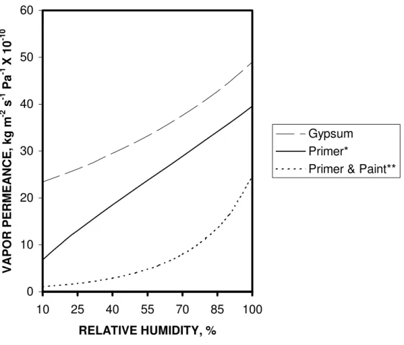
each membrane from the other or at least put them in different classes. This opens up opportunities for different vapor diffusion control strategies. If one plots the permeance of 6 mil polyethylene sheet in Figure 1, it will be a straight line parallel to the X-axis and very close to the base (at approximately 0.02 X 10⁻¹⁰ kg m-2 s-1 Pa-1). 6 mil polyethylene has been an effective vapor barrier in building applications. On the contrary, if one plots the permeance of interior gypsum board, as shown in Figure 3, the curve will start from 23 X 10-10 kg m-2 s-1 Pa-1 at 10 % RH and end at 49 X 10-10 kg m-2 s-1 Pa-1 at 100 % RH. This is a very permeable layer and will rapidly allow passage of water vapor across it. For example, it takes about a month to transport 5 g of water vapor across 1 m2 of 6 mil polyethylene sheet at a vapor pressure differential of 1000 Pa while the same transport occurs in 30 min across 1 m2 of the gypsum board. However, as shown in Figure 3, the very permeable gypsum board when coated with a primer and a latex paint changes into a vapor diffusion resistant or only moderately permeable material, at the lower range of RH.
Figure 1 shows that the membranes 60 Min-I, SBP-II, SBP-IV, and SBP-V are very permeable under all conditions of relative humidity while the membranes SBP-I, SBP-II and PerPoly-I are only moderately permeable. The membranes 10 I, 10 Min-II, 30 Min-I, 30 Min-Min-II, and 60 Min-II are moderately permeable at lower relative humidities and very permeable at higher relative humidities. The behaviours of the polyamide membrane and the #15 Felts belong to a separate category. At low relative humidities these effectively retard vapor flows while at very high relative humidities these are highly permeable – more permeable than gypsum board.
As discussed above, North American building membranes provide various opportunities for moisture management of exterior walls of buildings. Depending upon the moisture response of each wall design, various vapor diffusion control strategies can be implemented by choosing a membrane and deciding its relative position in the whole assembly. Detailed hygrothermal analyses will help assessing the effectiveness of such strategies[13,14]. Thus one can design either a permeable wall or a vapor diffusion resistant wall, manage the wall’s response to exterior and interior moisture loads and prolong the service life of such a wall.
ACKNOWLEDGEMENTS
The results reported here are partly from a consortium project called MEWS (Moisture Management for Exterior Wall Systems) that has been recently concluded at the Institute for Research in Construction. The rest of the results are from another project that was funded by ASHRAE RP-1018. The following partners supported the consortium and worked with the researchers from the Institute: Louisiana Pacific Corporation, Fortifiber Corporation, EI DuPont de Nemours & Co, Fibreboard Manufacturers Association of Canada, Canadian Plastics Industry Association, Forintek Canada Corporation, Marriott International Inc., EIFS Industry Members Association, Canadian Wood Council, Masonry Canada, and Canada Mortgage and Housing Corporation.
REFERENCES
1. Hens, H. 1996., Heat, Air and Moisture Transfer in Insulated Envelope Parts. Final Report, Volume 1, Task 1: Modelling, International Energy Agency Annex 24, Laboratorium Bouwfysica, K. U. -Leuven, Belgium, 1996.
2. Trechsel, H. R. (ed), “Moisture Analysis and Condensation Control in Building
Envelopes,” ASTM MNL 40, Appendices A to K, 2001, pp.161-184.
3. ASTM E 96-00, Standard test method for water vapor transmission of materials, 2001. ASTM International
4. ASTM C 522 - 87, Standard test method for Airflow Resistance of Acoustic Materials, 1995. ASTM International
5. Kumaran, M. K., Lackey, J. C., Normandin, N., van Reenen, D & Tariku, F. 2002b. A thermal and moisture transport property database for common building
and insulating materials. ASHRAE website, Research Project Report 1018-RP,
2002, p. 229.
6. Kumaran, M. K., Lackey, J. C., Normandin, N., van Reenen, D and Tariku, F.,
Summary report from Task 3 of MEWS project Hygrothermal Properties of Several Building Materials, Institute for Research in Construction, NRC Canada
(RR-110), 2002 p. 73.
7. Lackey, J. C., Marchand, R. G., and Kumaran, M. K., “A Logical Extension of the ASTM Standard E 96 to Determine the Dependence of Water Vapor Transmission on Relative Humidity,” Insulation Materials: Testing And
Applications: Third Volume, ASTM STP 1320, R. S. Graves and R. R. Zarr, Eds,
ASTM International, West Conshohocken, PA, 1997, pp. 456-470.
8. Kumaran, M. K., “An Alternative Procedure for the Analysis of Data from the Cup Method Measurements for Determination of Water Vapor Transmission Properties”, Journal of Testing and Evaluation, Vol. 26 , 1998, pp. 575-581.
9. Bomberg, M. T. and Kumaran, M.K., “A test method to determine air flow resistance of exterior membranes and sheathings,” Journal of Thermal Insulation, Vol. 9, 1986, pp. 224-235.
10. Kumaran, M. K., “Moisture Diffusivity of Building Materials from Water Absorption Measurements,” Journal of Thermal Envelope and Building Science, Vol. 22, 1999, pp. 349-355.
11. Hansen, K. K. and Lund, H. B., “Cup Method for Determination of Water Vapor Transmission Properties of Building Materials. Sources of Uncertainty in the Method,” Proceedings of the 2nd Symposium , Building Physics in the Nordic
Countries, Trondheim, 1990, pp. 291-298.
12. Hedenblad, G., “Moisture Permeability of Some Porous Building Materials,”
Proceedings of the 4th Symposium, Building Physics in the Nordic Countries,
Espoo, Vol. 2, 1996, pp. 747-754.
13. Kumaran M. K., Mukhopadhyaya P., Cornick S. M., Lacasse, M. A., Maref W., Rousseau M., Nofal M., Quirt J. D. & Dalgliesh W. A. “An integrated methodology to develop moisture management strategies for exterior wall systems.” 9th Conference on Building Science and Technology, Vancouver,
Canada, 2003, pp. 45-61.
14. Mukhopadhyaya, P., Goudreau, P., Kumaran, M. K. & van Reenen, D. 2002. “Influence of material properties on the hygrothermal response of an ideal stucco wall - Results from hygrothermal simulations.” 6th Nordic Building Physics
0 5 10 15 20 25 30 35 40 45 50 10 25 40 55 70 85 100 RELATIVE HUMIDITY, % VAPOR PERMEANCE, kg m -2 s -1 Pa -1 X 10 -10 60 Min-I SBP-II SBP-IV SBP-V SBP-I SBP-III PerPoly-I
Figure 1. The water vapor permeances of many permeable membranes are independent of the mean relative humidity; note that the permeances of SBP-I and PerPoly-I are almost identical.
0 10 20 30 40 50 60 70 10 25 40 55 70 85 100 RELATIVE HUMIDITY, % VAPOR PERMEANCE, kg m -2 s -1 Pa -1 X 10 -10 10 Min-I 30 Min-I 60-Min-II Felt-I Felt-III PAmide
Figure 2. The water vapor permeances of several membranes depend on the mean
relative humidity. The PAmide and Felt are highly resistant to vapor diffusion up to 70 % RH and then they become highly permeable at very high relative humidity.
0 10 20 30 40 50 60 10 25 40 55 70 85 100 RELATIVE HUMIDITY, % VAPOR PERMEANCE, kg m -2 s -1 Pa -1 X 10 -10 Gypsum Primer*
Primer & Paint**
Figure 3. The effect of one coat of a primer and one coat of the primer + two coats of a latex paint on the permeance of a ½ in. gypsum board.