READ THESE TERMS AND CONDITIONS CAREFULLY BEFORE USING THIS WEBSITE. https://nrc-publications.canada.ca/eng/copyright
Vous avez des questions? Nous pouvons vous aider. Pour communiquer directement avec un auteur, consultez la première page de la revue dans laquelle son article a été publié afin de trouver ses coordonnées. Si vous n’arrivez pas à les repérer, communiquez avec nous à PublicationsArchive-ArchivesPublications@nrc-cnrc.gc.ca.
Questions? Contact the NRC Publications Archive team at
PublicationsArchive-ArchivesPublications@nrc-cnrc.gc.ca. If you wish to email the authors directly, please see the first page of the publication for their contact information.
NRC Publications Archive
Archives des publications du CNRC
This publication could be one of several versions: author’s original, accepted manuscript or the publisher’s version. / La version de cette publication peut être l’une des suivantes : la version prépublication de l’auteur, la version acceptée du manuscrit ou la version de l’éditeur.
Access and use of this website and the material on it are subject to the Terms and Conditions set forth at
Analysis of uncertainties in calibration of a heat flow meter apparatus
Bomberg, M. T.; Pelanne, C. M.; Newton, W. S.
https://publications-cnrc.canada.ca/fra/droits
L’accès à ce site Web et l’utilisation de son contenu sont assujettis aux conditions présentées dans le site LISEZ CES CONDITIONS ATTENTIVEMENT AVANT D’UTILISER CE SITE WEB.
NRC Publications Record / Notice d'Archives des publications de CNRC:
https://nrc-publications.canada.ca/eng/view/object/?id=4cd3d252-c6e1-4f8e-b424-9f4b17464df6 https://publications-cnrc.canada.ca/fra/voir/objet/?id=4cd3d252-c6e1-4f8e-b424-9f4b17464df6Ser
/ 3 - .
,$"THl
N21d
National Research
Conseil national
no.
1300
h&
c .
2ouncil Canada
de recherches Canada
IBLDG
Division of
Division des
- P A
Building Research
recherches en batiment
Analysis of Uncertainties in
Calibration of a Heat Flow
Meter Apparatus
by M. Bomberg, C.M. Pelanne and W.S. Newton
ANALYZED
Reprinted from
"Thermal Conductivity 18"
Session J
-
Measurement Apparatus, p. 259
-
272
Proceedings of the Eighteenth International
Conference on Thermal Conductivity
Rapid City, S. Dakota, October 3-5, 1983
DBR
Paper
No.
1300
Price $1.25
NRCC 24690
RESUME
Cette communication analyse les principales sources d'incertitude dans les mesures en laboratoire de la resistance thermique B l'aide d'un fluxmetre thermique et ce, pour une vaste gamme de conditions d'essai. Elle traite en termes gensraux des erreurs d'etalonnage, indique les techniques pour assurer la precision de l'instrument, analyse la sensibilite des resultats 3 certains changernents dans les conditions d'essai et decrit deux methodes permettant d'etablir des normes de correspondance pour la cornparaison des mesures absolues et relatives. - - - 1 - - - - - I - - - - - -
--
I-
From:
THERMAL
CONDUCTIVlTY 18
Edited
by
T. Ashwo*
andDavid
R.
Slnih
(Plaurn
Publishing
Capnatim,
1385)
ANALYSIS OF UNCERTAINTIES I N CALIBRATION OF A HEAT FLOW METER APPARATUS
M. Bomberg-National Research Council of Canada, Ottawa, O n t a r i o
C .M. Pelanne
-
Manville Corporation of U. S., Denver, ColoradoWendy S
.
Newton-
Manville Canada Inc.,
I n n i s f a i l , A l t a .ABSTRACT
This paper reviews t h e main s o u r c e s of u n c e r t a i n t y i n
l a b o r a t o r y measurement of thermal r e s i s t a n c e w i t h a h e a t flow m e t e r a p p a r a t u s over a wide range of t e s t i n g c o n d i t i o n s . It d e a l s w i t h c a l i b r a t i o n u n c e r t a i n t i e s i n g e n e r a l terms, i n d i c a t e s t e c h n i q u e s f o r c o n t r o l l i n g i n s t r u m e n t p r e c i s i o n , a n a l y s e s t h e s e n s i t i v i t y of r e s u l t s t o some changes i n t e s t i n g c o n d i t i o n s , and d e s c r i b e s two procedures f o r e s t a b l i s h i n g t r a n s f e r s t a n d a r d s t h a t permit comparison o f a b s o l u t e and r e l a t i v e measurements.
INTRODUCTION
E r r o r s i n measurements w i t h t h e h e a t flow meter (HFM)
a p p a r a t u s a r i s e o u t of u n c e r t a i n t i e s i n e l e c t r i c a l and t h i c k n e s s measurements, a s w e l l a s o u t of d e v i a t i o n s from one-dimensional h e a t flow and u n c e r t a i n t y i n t h e HFM c a l i b r a t i o n f a c t o r . Bomberg and Solvason [ l ] have compared v a r i o u s c a l i b r a t i o n t e c h n i q u e s and concluded t h a t t h e HFM a p p a r a t u s c a l i b r a t i o n u s i n g t r a n s f e r s t a n d a r d s i s t h e p r e f e r r e d technique. The u s e of t r a n s f e r
s t a n d a r d s ( o r c a l i b r a t e d specimens) r e q u i r e s , however, t h a t guarded h o t p l a t e (GHP) t e s t s be performed on a v a r i e t y of m a t e r i a l s . I f
t h e HFM a p p a r a t u s i s t o b e used f o r q u a l i t y c o n t r o l i n
manufacturing of thermal i n s u l a t i o n , t h e t r a n s f e r s t a n d a r d should be made of t h e same m a t e r i a l 121, and t h i s may i n t r o d u c e a
s i g n i f i c a n t i n c r e a s e i n t h e u n c e r t a i n t i e s of b o t h HFM and GHP t e s t r e s u l t s .
E r r o r s a s s o c i a t e d w i t h GHP equipment have a l r e a d y been d i s c u s s e d [ 3 ] , b u t t h e e f f e c t of t h e c h a r a c t e r i s t i c $ o f t h e m a t e r i a l under t e s t have not: P t e c i s i o n of t h e GHP a p p a r a t u s was shown t o be s t r o n g l y dependent on u n i f o r m i t y of h e a t flow a c r o s s t h e gap between t h e metering and guard r i n g a r e a s ; and o n l y homogeneous, uniform, " i d e a l " specimens c o u l d b e used f o r experimental d e t e r m i n a t i o n of t h e u n c e r t a i n t i e s i n GHP t e s t i n g .
I d e a l l y , c a l i b r a t i o n of t h e h e a t flow s e n s o r (HFS) should n o t vary w i t h specimen t h i c k n e s s . Thin, uniform specimens c o u l d t h e n be used t o u t i l i z e , a s t h e c a l i b r a t i o n base, t h e h i g h l e v e l of p r e c i s i o n and accuracy p o s s i b l e w i t h t h e GHP a p p a r a t u s . Changes i n t h e design of t h e h e a t flow meter a p p a r a t u s t o reduce t h e e f f e c t s of l a t e r a l h e a t flow on t h e c a l i b r a t i o n of t h e h e a t flow t r a n s d u c e r have been d e s c r i b e d [ I ] . The new d e s i g n makes t h e c a l i b r a t i o n c o e f f i c i e n t l e s s dependent on t h e c h a r a c t e r i s t i c s of t h e m a t e r i a l being t e s t e d and produces t h e same c a l i b r a t i o n curve f o r b o t h
t h i c k , low-density specimens and t h i n , high-density ones. The
range of c o n d i t i o n s under which m a t e r i a l s may be t e s t e d a c c u r a t e l y i s t h u s enlarged. These a s p e c t s w i l l be d i s c u s s e d i n t h e p r e s e n t paper and i n a n o t h e r [ 4 ] t h a t d e s c r i b e s t h e v e r i f i c a t i o n of h e a t flow m e t e r s used f o r q u a l i t y c o n t r o l i n t h e p r o d u c t i o n of low- d e n s i t y mineral f i b e r i n s u l a t i o n . Both papers a r e based on a c o o p e r a t i v e s t u d y c a r r i e d o u t by t h e D i v i s i o n o f B u i l d i n g Research, National Research Council of Canada (NRCC), t h e Research and
Development D i v i s i o n of Manville Corporation, USA, and t h e Q u a l i t y Control Group i n t h e I n n i s f a i l P l a n t of Manville Canada Inc.
This paper reviews a s e l e c t i o n of m a t e r i a l s and t e s t c o n d i t i o n s used f o r c a l i b r a t i o n and c e r t a i n a s p e c t s o f HFM a p p a r a t u s performance ( i . e . , measurements of temperature and specimen t h i c k n e s s ) , and d i s c u s s e s t h r e e t e c h n i q u e s s u i t a b l e f o r examining u n c e r t a i n t i e s due t o t e s t i n g procedure. A l l u t i l i z e a i r l a y e r s , l a y e r e d low-density g l a s s f i b e r specimens, and adjustment of ambient temperature t o s t u d y t h e l a t e r a l h e a t flow e f f e c t . The importance of m a t e r i a l s t r u c t u r e i n t h e development o f a t r a n s f e r s t a n d a r d i s s t r e s s e d .
T e s t Conditions f o r C a l i b r a t i o n of HFM Apparatus
A s t h e p r e c i s i o n and accuracy of a n HFM t e s t depends on t h e c o n s t r u c t i o n of t h e a p p a r a t u s a s w e l l a s t h e t e s t i n g procedure, both f a c t o r s must be considered i n s e l e c t i n g a range of t e s t c o n d i t i o n s . A t NRCC a 600- x 600-rnm HFM a p p a r a t u s i s u s e d t o t e s t low-density thermal i n s u l a t i o n s up t o 150 mm t h i c k ( o r up t o 200 mm w i t h somewhat lower t e s t p r e c i s i o n ) . The working r a n g e i s between 6 and 180 mm, corresponding t o a thermal r e s i s t a n c e range of 0.2 t o 7 m 2 ~ / w .
M a t e r i a l acceptance s t a n d a r d s u s u a l l y r e q u i r e thermal t e s t i n g a t a mean temperature of 24 'l°C, w i t h a temperature d i f f e r e n c e o f 22 deg (Canada), o r 27 deg (USA). To e s t a b l i s h t h e dependence of thermal r e s i s t a n c e on mean temperature, t e s t s a r e normally
conducted over a range of mean temperatures from 0 t o 50 deg C.
I
T r a n s f e r Standard and Reference M a t e r i a l sA change i n t e s t i n g c o n d i t i o n s , even one s o small t h a t i t may n o t be observed by t h e o p e r a t o r , may produce s i g n i f i c a n t d e v i a t i o n s i n measured r e s u l t s , depending on t h e n a t u r e of t h e t e s t e d
m a t e r i a l . Although q u a l i t y c o n t r o l c a n s e l e c t a r e f e r e n c e specimen of t h e same m a t e r i a l a s t h a t being c o n t r o l l e d , a n independent t e s t i n g l a b o r a t o r y must have s e v e r a l r e f e r e n c e specimens. A t NRCC
t h e following m a t e r i a l s a r e used t o e s t a b l i s h t r a n s f e r s t a n d a r d s because of t h e i r u n i f o r m i t y , time s t a b i l i t y , and h a n d l i n g
q u a l i t i e s : expanded p o l y s t y r e n e ( p r e f e r a b l y h i g h d e n s i t y ) o r , a l t e r n a t i v e l y , air-f i l l e d e x t r u d e d polystyrene; medium o r high- d e n s i t y g l a s s f i b e r , e.g., s t a n d a r d r e f e r e n c e m a t e r i a l s (SRM) 1450 from t h e N a t i o n a l Bureau of Standards [ 5 ] . I n a d d i t i o n , NRCC h a s a set of l a y e r e d , low-density g l a s s f i b e r t r a n s f e r s t a n d a r d s t o v e r i f y t e s t i n g of m a t e r i a l s w i t h a s i g n i f i c a n t f r a c t i o n o f r a d i a t i v e h e a t t r a n s p o r t .
I
Apparatus C o n s t r u c t i o nThe accuracy of a n HFM depends on s e v e r a l f a c t o r s r e l a t e d t o t h e c o n s t r u c t i o n of t h e apparatus: f o r example, f l a t n e s s and p a r a l l e l i s m of t h e h o t and cold p l a t e s ( t h e s e f a c t o r s a r e d e s c r i b e d i n ASTM C518 [ 2 ] ) .
I
Temperature MeasurementThe following c h a r a c t e r i s t i c s r e l a t e d t o temperature measurement must b e checked:
P (1) temperature u n i f o r m i t y
-
uniformity o r d i f f e r e n c e s i ntemperatures measured o v e r t h e s u r f a c e of t h e p l a t e s , ( 2 ) temperature s t a b i l i t y w i t h time, and
1
(3) r e p e a t a b i l i t y of temperature measurements.I Temperature u n i f o r m i t y and s t a b i l i t y can be determined by a d j u s t i n g
b o t h HFM p l a t e s t o t h e same temperature and p l a c i n g them i n c o n t a c t with each o t h e r . The s t a n d a r d d e v i a t i o n f o r each thermocouple r e c o r d i n g w i l l i n d i c a t e s t a b i l i t y , w h i l e t h e range between minimum and maximum measured s u r f a c e temperatures w i l l i n d i c a t e temperature u n i f o dt y .
The p r e c i s i o n of measurement of a temperature d i f f e r e n c e depends on t h e t e m p e r a t u r e d i f f e r e n c e used i n t h e t e s t . For
example, 0.1 C deg means a n u n c e r t a i n t y of 1% f o r a l o - d e g temperature d i f f e r e n c e b u t a n u n c e r t a i n t y o f only 0.5% f o r t h e u s u a l 22- t o 27-deg d i f f e r e n c e . A good HFM a p p a r a t u s h a s , f o r example, t e m p e r a t u r e u n i f o r m i t y b e t t e r t h a n -+0.15OC, temperature s t a b i l i t y b e t t e r than -+0.02"C, and r e p e a t a b i l i t y p r e c i s i o n (with readings on DVM) of 1.0%. Thickness Measurement I f t h e HFM a p p a r a t u s i s provided w i t h a t h i c k n e s s i n d i c a t o r , t h e z e r o p o s i t i o n and l i n e a r i t y of t h e t h i c k n e s s gauge s h o u l d b e checked a s w e l l a s t h e p a r a l l e l i s m of t h e two p l a t e s e n c l o s i n g t h e specimen [41. A t NRCC, specimen t h i c k n e s s i s c a l c u l a t e d a s t h e average of t h e d i s t a n c e between p l a t e s measured on each s i d e of t h e apparatus. T h i s procedure i n c l u d e s a check of p a r a l l e l i s m a s w e l l a s a n averaging of a number of measurements.
A d d i t i o n a l c o n s i d e r a t i o n i s given t o a l l h i g h p r e c i s i o n measurements ( s u c h a s c a l i b r a t i o n ) , namely, comparison of specimen t h i c k n e s s measured i n s i d e and o u t s i d e t h e HFM apparatus. The two t h i c k n e s s e s a r e p e r m i t t e d t o d i f f e r by as much a s -+0.2%. If t h e t h i c k n e s s measured i n t h e a p p a r a t u s d i f f e r s by more t h a n t h i s , t h e t e s t i s excluded from t h e c a l i b r a t i o n s e r i e s ; i f t h e d i f f e r e n c e i s l e s s than 0.1%, no c o r r e c t i o n i s made; i f t h e d i f f e r e n c e i s between 0.1 and 0.22, a n a p p r o p r i a t e c o r r e c t i o n i s applied.
UNCERTAINTIES RELATING TO TESTING PROCEDURE
A l a b o r a t o r y r o u t i n e f o r t e s t i n g must be e s t a b l i s h e d ,
i n c l u d i n g methods of p r e p a r i n g specimens ( d r y i n g o r c o n d i t i o n i n g ) :
measure d e n s i t y and t h i c k n e s s of specimen o u t s i d e and i n s i d e t h e a p p a r a t u s , e s t i m a t e time t o r e a c h t h e s t e a d y - s t a t e c o n d i t i o n ; record, c a l c u l a t e and r e p o r t temperatures and h e a t f l u x . Then s e l e c t a m a t e r i a l known f o r u n i f o r m i t y and time s t a b i l i t y t o e s t a b l i s h "a s t a n d a r d r e p e a t a b i l i t y p r e c i s i o n , " i.e. r e p e a t a b i l i t y o b t a i n e d i n s t a n d a r d t e s t i n g c o n d i t i o n s on t h e r e f e r e n c e m a t e r i a l . This b a s i c measure of r e p e a t a b i l i t y p r e c i s i o n (two s t a n d a r d
d e v i a t i o n s on minimum n i n e t e s t r e s u l t s ) may t h e n b e compared t o t h e r e p e a t a b i l i t y p r e c i s i o n o b t a i n e d f o r d i f f e r e n t m a t e r i a l s o r changing t e s t c o n d i t i o n s , f o r example, when t e s t i n g i n t h e range of -
mean temperature. These concepts may be i l l u s t r a t e d by t h e
following: s t a n d a r d r e p e a t a b i l i t y p r e c i s i o n r e l a t e d t o 90%
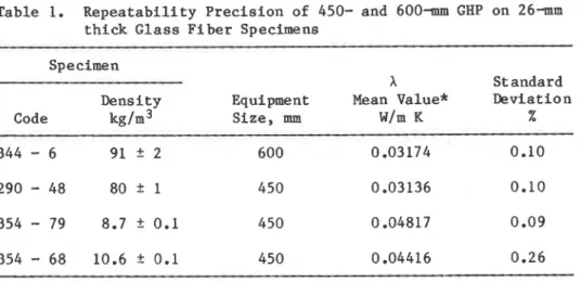
p r o b a b i l i t y l e v e l , i.e., two s t a n d a r d d e v i a t i o n s , i s approximately 0.2% f o r high-density g l a s s f i b e r specimens 344-6 ( T a b l e 1 ) on t h e
6001mn GHP and f o r specimens 290-48 on t h e 450- GHP.
R e p e a t a b i l i t y p r e c i s i o n determined on low-density g l a s s f i b e r (LDGF) specimens, code 354-79, i s i n t h e same range a s t h a t f o r t h e HDGF specimens; f o r LDGF specimens, code 354-68, r e p e a t a b i l i t y
Table 1. R e p e a t a b i l i t y P r e c i s i o n of 450- and 600- GHP on 26-m t h i c k Glass F i b e r Specimens
Specimen
X Standard
Density Equipment Mean Value* Deviation
Code kg/m3 S i z e , mm W/m K %
354
-
79 8.7+
0.1 450 0.04817 0.09r
3 5 4 - 68 10.6
+
0.1 450 0.04416 0.26*
L a s t d i g i t shown f o r c a l c u l a t i o n purposes onlyp r e c i s i o n i s almost t h r e e times poorer. It a p p e a r s t h a t r e p e a t a b i l i t y p r e c i s i o n of t h e GHP a p p a r a t u s depends on t h e specimens s e l e c t e d f o r t e s t i n g . From t e s t s on t h e 600- and 450-m GHP's shown i n T a b l e 1 r e p e a t a b i l i t y p r e c i s i o n of t h e i n s t r u m e n t s on a 95% p r o b a b i l i t y l e v e l a p p e a r s t o be 0.2%. The lower p r e c i s i o n a p p a r e n t i n some of t h e t e s t s must b e a t t r i b u t e d t o t h e e f f e c t s o f specimen p r e p a r a t i o n and c o n d i t i o n i n g , and perhaps t o some o t h e r m a t e r i a l v a r i a b l e .
I
E f f e c t of L a t e r a l Heat FlowI n t e s t i n g t o determine t h e s i g n i f i c a n c e of l a t e r a l h e a t f l o w , t h e same temperature i s maintained on b o t h p l a t e s and ambient a i r :
temperature i s c o n s t a n t but much lower. Heat l o s s from t h e edge of t h e specimen c a n be assumed symmetrical, h a l f from t h e "hot" p l a t e and h a l f from t h e "cold" p l a t e . Output from t h e h e a t flow
t r a n s d u c e r , c o r r e c t e d f o r any s m a l l temperature d i f f e r e n c e a c r o s s t h e specimen, w i l l g i v e t h e edge l o s s a s s o c i a t e d w i t h t h e
temperature d i f f e r e n c e between t h e two p l a t e s and ambient a i r .
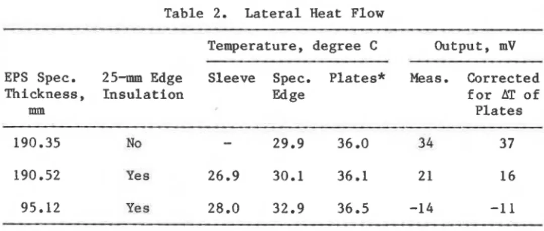
I A s a n example, Table 2 shows t h e r e s u l t s of a s e r i e s of l a t e r a l h e a t flow t e s t s conducted a t NRCC on a p a r t i c u l a r
apparatus* u s i n g 95- and 190- t h i c k p o l y s t y r e n e specimens. It i s
e v i d e n t t h a t t h e t e m p e r a t u r e d i f f e r e n c e between t h e t e m p e r a t u r e c o n t r o l l e d e n c l o s u r e surrounding t h e specimen ( t h e s l e e v e ) and t h e HFM p l a t e s c a u s e s a measurable o u t p u t from t h e t r a n s d u c e r ( e r r o r ) . It i s a l s o e v i d e n t t h a t t h e u s e of edge i n s u l a t i o n reduces t h i s e r r o r .
*
Manufactured by Foundation E l e c t r o n i c I n s t r u m e n t s , Ottawa, Canada.Table 2. L a t e r a l Heat Flow
Temperature, degree C Output, mV EPS Spec. 25- Edge Sleeve Spec. P l a t e s *
Thickness, I n s u l a t i o n Edge mm 190.35 No
-
29.9 36.0 190.52 Yes 26.9 30.1 36.1 95.12 Yes 28.0 32.9 36.5 Meas. Corrected f o r AT o f P l a t e s34
3 7*
Both p l a t e s maintained a t t h e same temperatureI f t h e l a t e r a l h e a t flow component i s l e s s t h a n 0.5% of t h e average o u t p u t of t h e h e a t flow meter ( i . e . , 3-5 vV i n T a b l e 2 ) , edge i n s u l a t i o n should n o t be r e q u i r e d when t e s t i n g t h i n specimens. A d i f f e r e n c e of up t o 2 C deg between s l e e v e temperature and mean specimen temperature may be accepted i f t h e specimen t h i c k n e s s does n o t exceed 40 mm. Specimens t h i c k e r t h a n 60 mm should, however, b e t e s t e d w i t h edge i n s u l a t i o n . For t h o s e t h i c k e r t h a n 90 mm, t h e d i f f e r e n c e between s l e e v e and mean specimen t e m p e r a t u r e s s h o u l d b e l i m i t e d t o 1 C deg.
Use of A i r Layers
Air l a y e r s can be used a s t e s t specimens t o v e r i f y t h e
accuracy of t h e HFM a p p a r a t u s when c o n v e c t i o n o f a i r i s e l i m i n a t e d and t h e thermal c o n d u c t i v i t y of s t i l l a i r i s e i t h e r known o r determined from t e s t r e s u l t s f o r a t l e a s t two l e v e l s of p l a t e e m i t t a n c e and two o r t h r e e a i r l a y e r t h i c k n e s s e s . The l a t t e r approach was proposed by K l a r s f e l d [ 6 ] a s a n e x t r a p o l a t i v e procedure i n which thermal c o n d u c t i v i t y of s t i l l a i r ( 1 ) can b e determined. This procedure c o n s i s t s of e x t r a p o l a t i o n
t8
z e r o t h i c k n e s s f o r t h e following:( 1 ) apparent thermal c o n d u c t i v i t y * of a n a i r l a y e r a t a given mean a i r temperature f o r e a c h v a l u e of boundary emi t t a n c e ,
(2) apparent thermal c o n d u c t i v i t y * of a n a i r l a y e r and known boundary e m i t t a n c e f o r a g i v e n v a l u e of mean a i r temperature.
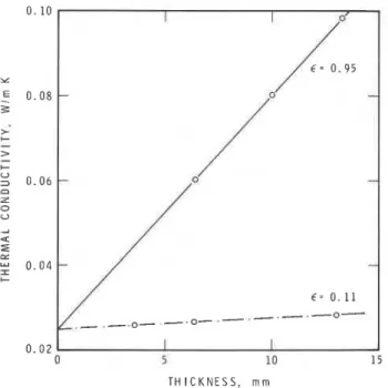
F i g u r e 1 shows NRCC d a t a f o r apparent thermal c o n d u c t i v i t i e s of t h r e e a i r l a y e r s t e s t e d w i t h and w i t h o u t aluminum , f o i l s ( o n b o t h
- -
*
For b r e v i t y , "apparent" i s dropped i n subsequent d i s c u s s i o n s . Thermal c o n d u c t i v i t y of a n a i r l a y e r o r of low-density thermal i n s u l a t i o n s means, however, a p p a r e n t t h e r m a l c o n d u c t i v i t y .0 . 0 2
0 5 10 15
T H I C K N E S S , m m
Fig. 1. Thermal c o n d u c t i v i t i e s of a n a i r l a y e r , w i t h and w i t h o u t aluminum f o i l , e x t r a p o l a t e d t o determine s t i l l - a i r c o n d u c t i v i t y . Measured i n 600- GHP a p p a r a t u s
s i d e s of t h e a i r l a y e r ) , a t t h e same mean temperature, and w i t h a temperature d i f f e r e n c e of 28 C deg a c r o s s t h e a i r gap [ 7 ] .
E x t r a p o l a t i n g t h e d a t a t o z e r o t h i c k n e s s , one o b t a i n s a s t i l l - a i r c o n d u c t i v i t y of 0.0247 W/m K a t a mean temperature o f 24OC. It i s somewhat lower t h a n t h e 0.0254 W/m K shown f o r a i r a t 297 K by r Raznjevic [ 8 ] o r t h e 0.0252 W/m K quoted i n t h e Smithsonian
P h y s i c a l Tables [ 9 ] . The l e v e l s t i l l - a i r c o n d u c t i v i t y can t h e n b e used t o c a l c u l a t e p l a t e e m i t t a n c e u s i n g t e c h n i q u e s d e s c r i b e d by
'
Hager [ l o ] and Pelanne [ l l ] .I n a d d i t i o n t o t h e d a t a shown i n Fig. 1, e i g h t o t h e r t e s t s o n a 10-mm a i r gap o v e r a mean temperature r a n g e of 0 t o 45OC y i e l d e d t h e f o l l o w i n g equation:
Data generated from i t can be compared w i t h v a l u e s i n Refs. 8 and 9 , making t h i s method u s e f u l f o r v e r i f y i n g t h e temperature c o e f f i c i e n t of t h e c a l i b r a t i o n curve.
U s e of Layered, Low-density, Glass F i b e r Specimens
A technique used a t NRCC t o f a b r i c a t e low-density t r a n s f e r s t a n d a r d s r a n g i n g i n t h i c k n e s s from 50 t o 250 mm i s s l i g h t l y
d i f f e r e n t from t h a t d e s c r i b e d i n Ref. 4. Using a l i g h t t a b l e [ 1 2 ] , t h i r t y 12-mm t h i c k , low-density g l a s s f i b e r specimens were s e l e c t e d
a s most uniform among one hundred and t h i r t y . Their d e n s i t i e s
v a r i e d between 8.2 and 10.0 kg/m3. To reduce t h e number of t e s t s
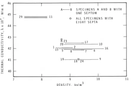
t o be performed, p a i r s of specimens,each s e p a r a t e d by a paper septum t o i n t e r c e p t r a d i a t i v e h e a t t r a n s f e r , were t e s t e d a t one time. The r e s u l t s of t h e thermal c o n d u c t i v i t y tests a r e shown i n
Fig. 2. Some of t h e specimens were recombined i n new p a i r s and
n i n e p a i r s were f i n a l l y s e l e c t e d . The r e s u l t s of thermal
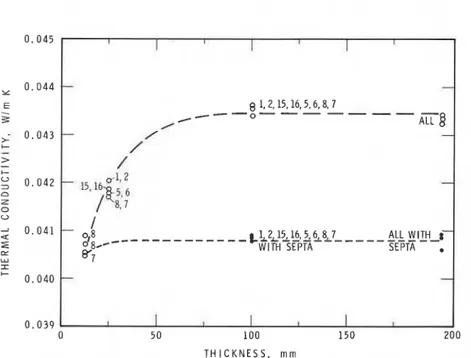
c o n d u c t i v i t y tests on a g l a s s f i b e r s t a c k , w i t h and w i t h o u t paper s e p t a , are shown i n Fig. 3.
Layered specimens a r e p a r t i c u l a r l y u s e f u l i n examining t h e e f f e c t of specimen t h i c k n e s s [13,14] on a p p a r e n t t h e r m a l
c o n d u c t i v i t y measured f o r a g i v e n s e t of test c o n d i t i o n s . The i n s t r u m e n t e r r o r h a s been e s t i m a t e d ( a n o t h e r approximative model has a l s o been p r e s e n t e d [ 1 5 ] ) by assuming t h a t a l l test r e s u l t s w i t h r a d i a t i o n - a b s o r b i n g b a r r i e r s ( p a p e r s e p t a ) p l a c e d 25 mm a p a r t
should be e q u a l t o t h e r e s u l t s o b t a i n e d on 25- t h i c k specimens a l o n e [ 4 ] . Although s u c h a n approximation a p p e a r s t o be a c c e p t a b l e f o r m i n e r a l f i b e r i n s u l a t i o n s , i t h a s n o t been proved f o r low- d e n s i t y c e l l u l a r p l a s t i c s . A-B S P E C I M E N S A A N D B W I T H - O N E S E P T U M 2 9 11 0 A L L S P E C I M E N S W I T H E I G H T S E P T A
-
7 8 9 10 11 D E N S I T Y , k g l m 3Fig. 2. Thermal c o n d u c t i v i t i e s of two specimens s e p a r a t e d by paper septum. R e s u l t of p r e l i m i n a r y s e r i e s used f o r specimen s e l e c t i o n
I I I I
-
81.2,15,16.5,6.8,7 C - O - - -----
-
/ - - ALL8
-/
/'
-
I
-
-
II
I I I I 5 0 100 1 5 0 T H I C K N E S S , m mFig. 3. Thermal conductivity of glass fiber stack with and without paper septa. Eighteen layers, each 12.5 mm, were tested
Fig. 4. Thermal conductivity of polystyrene stack with and without I I I I I I - - - / o / o - O -
-
W I T H O U T S E P T A:(
-
f -4' F'C" W I T H S E P T A-
,eO=-1
0-
--
I I I I I I T H I C K N E S S , rnrnFor comparison, Fig. 4 shows the results of two series of tests on the same batch of expanded polystyrene, density
15-16 kg/m3, with and without paper septa. The curve of thermal conductivity versus specimen thickness shows a different character from that of Fig. 3, implying a somewhat different mechanism of radiative heat transport. Layered low-density glass fiber
insulation appears, therefore, to be more suitable for verification of the HFM apparatus [ 16,171 than low-density expanded polystyrene insulation, although radiative heat transport is a significant fraction of the total heat transfer for both types of insulation. Importance of Material Structure
The foregoing discussion of repeatability (reproducibility) precision illustrates the importance of test specimens of uniform material structure. Some lowdensity glass fiber specimens
(e.g., 354-79, Table 1) were shown to have the same precision of repeatability as the high-density glass fiber standard reference material (SRM) produced by the National Bureau of Standards [5], but much lower precision was achieved with other specimens. Use of thick specimens of low-density thermal insulation for calibration purposes usually led to lower precision than could be achieved with high-density, standard reference material [ 1 8 ] . As the precision of thermal conductivity determination is inversely proportional to specimen thickness, an alternative approach would be to fabricate thick specimens from thin layers already tested separately. This can only be done, however, if the material has a high degree of structural uniformity.
Specimens of almost identical density and thermal conductivity were selected at the Innisfail plant [4]. Specimens with thermal conductivity very close to that calculated as a function of density from the model [15] were used for the NRCC tests shown in Fig. 3. In both cases, however, the specimens were chosen with a light table to ensure structure uniformity.
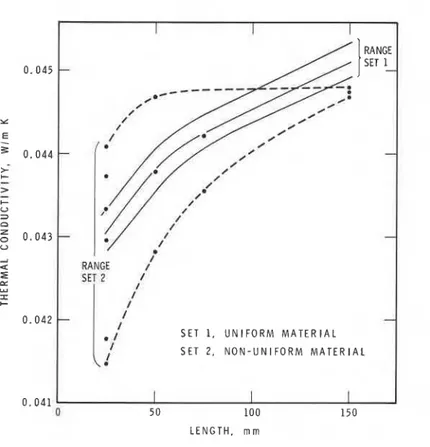
Figure 5 illustrates the importance of structure uniformity on
'
precision, showing the range of measured thermal conductivities as a function of specimen thickness for two sets of specimens of different uniformity:Set 1 contains six 25- thick lowdensity glass fiber specimens of good uniformity;
Set 2 contains six 25- thick specimens of poor uniformity selected as the extremes from the same sample as Set 1.
The variability in thermal conductivity was about 1% for a density variation of 9% in Set 1; a range of 5% in thermal conductivity was observed for a 15% range in density in Set 2. Figure 5 also shows
RANGE /' RANGE -
-
/- S E T 1. U N I F O R M M A T E R I A L S E T 2 , N O N - U N I F O R M M A T E R I A L L E N G T H , m mFig. 5. Range of thermal c o n d u c t i v i t i e s a s a f u n c t i o n of specimen t h i c k n e s s f o r low-density g l a s s f i b e r
S e t 1
-
s i x 25- t h i c k , uniform specimens S e t 2-
s i x 25-m t h i c k , non-uniform specimenst h a t a d i f f e r e n t curve of thermal c o n d u c t i v i t y a s a f u n c t i o n of t h i c k n e s s i s o b t a i n e d f o r e a c h of t h e s e t s , a l t h o u g h a l a r g e and
I s t a t i s t i c a l l y s i g n i f i c a n t number of t e s t s were performed.
One must remember t h a t p r o p e r t i e s of a m a t e r i a l vary i n a l l t h r e e d i r e c t i o n s and t h a t t h e manner i n which specimens a r e s e l e c t e d f o r comparative t e s t s may have a d e c i s i v e e f f e c t on t h e s t u d i e d dependence. I n p r e v i o u s work [ 4 ] specimens w i t h t h e same thermal c o n d u c t i v i t y and d e n s i t y b u t d i f f e r e n t t h i c k n e s s were s e l e c t e d . The r e l a t i o n between thermal c o n d u c t i v i t y and d e n s i t y of specimens was a l s o maintained i n t h e f i n a l s e l e c t i o n of t h e matched p a i r s i n t h e p r e s e n t r e s e a r c h (Fig. 2). It was n o t , however,
observed i n s e l e c t i n g S e t s 1 and 2 of Fig. 5.
These r e s u l t s a r e n o t s u r p r i s i n g a t a l l i f one a l s o remembers t h a t f o r a g i v e n f i b e r d i a m e t e r t h e r e l a t i o n between thermal
conductivity and glass fiber specimen density* describes material structure [15]. Comparison of Figs. 3 and
5
shows that in studying functional dependence one must use specimens with identicalstructure.
CONCLUSIONS
Calibration of a heat flow meter apparatus used for quality control of manufactured products can be extended to a wide range of testing conditions. Air layers and layered, low-density glass fiber transfer standards have been very useful in calibrating and verifying HFM apparatus precision and accuracy.
Lateral heat flow tests performed at the extreme thickness to be tested and determination of the mean temperature dependence of the calibration coefficient are also helpful in establishing the range of uncertainties caused by changes in test conditions.
This and previous NRCC studies [1,3,4] suggest that with proper calibration and careful verification of its errors, the HFM apparatus can replace the GHP apparatus in many industrial and commercial testing programs.
ACKNOWLEDGEMENT
I
The authors wish to thank J.G. Theriault, R.G. Marchand and Nicole Normandin, of the Thermal Insulation Laboratory, DBWNRCC, for their contribution to the development of testing facilities and transfer standards and for making the measurements. They also wish to express their gratitude to S. IUarsfeld, C.R.I.R.,
Isoverst. Gobain, Rantigny, France, to K.R. Solvason, DBWNRCC, for detailed discussion of the development of transfer standards for calibration and verification of the HFM apparatus, and to J.R. Sasaki, DBRINRCC, for careful review of the manuscript.
Particular thanks are offered to R. Boisvert, Manager of the 4
Manville Plant in Montreal, for preparation of the 130 specimens used for selection and development of NRCC low-density glass fiber
transfer standards. I
This paper is a contribution of the Division of Building Research, National Research Council of Canada, and is published with the approval of the Director of the Division.
*
Only if a material is uniform will the specimen density be identical to that of the metering section.REFERENCES
1. Bomberg, M., and Solvason, K.R., Comments on calibration and design of a heat flow meter; ASTM, STP 789, 277-292 (1983).
1
2. ASTM C518-1976, Part 18, 1982 Book of ASTM Standards.3. Bomberg, M., and Solvason,
K.R.,
Precision and accuracy ofguarded hot plate method; Proc., 17th International Thermal Conductivity Conf., Plenum Press, 393-410 (1983).
4. Newton, Wendy S., Pelanne, C.M., and Bomberg, M., Calibration of heat flow meter apparatus used for quality control of l o w
I
density mineral fiber insulations; Proc., 18th InternatinalConductivity Conference, Rapid City
,
SD.(1
983).5.
Siu, M.C.I., Fibrous glass board as a standard referencematerial for thermal resistance measurement systems; ASTM,
STP
718, 343-360 (1980).6. Klarsfeld, S., Letter to the IS0 International Thermal Conductance Round-Robin proposing foil-faced frames for a i r gap layer study, 20 February 1981.
7. Cammerer, W.F., Experimental determination of the equivalent thermal conductivity of air space at low temperatures; Presented to Committee BI, Int. Institute of Refrigeration, Washington, D.C. (Sept. 1976).
8. Raznjevic,
K.,
Thermal tables and diagrams based onWltemaschinen Regeln (in Polish), 5th ed., Karlsruhe, Miiller Press, 1958.
9. Smithsonian Physical Tables, 9th Ed. (ed. by W.E. Forsythe),
Smi thsonian Institution, Washington, D.C., Publ. 4169,
Vol. 120, 1954.
10. Hager, N.E., Method for measuring total hemispheric emissivity of plane surfaces with conventional thermal conductivity apparatus; 7th Conference on Thermal Conductivity, Gaithersburg, MD, National Bureau of Standards Spec. Publ. 302, 1968.
11. Pelanne, C.M., Experiments on the separation of heat transfer mechanisms in low-density fibrous insulation; 8th Conference on Thermal Conductivity, Plenum Press, 897-911, 1969.
12. Pelanne, C.M., Light transmission measurements through glass fiber insulations, ASTM, STP 660, 263-280, 1978.
13. Albers, M.A. and Peianne, C.M., An experimental and
mathematical study of effect of thickness in low density glass fiber insulation; Thermal Conductivity 17, Proc., 17th
International Thermal Conductivity Conference, Plenum Press, 471-482, 1983.
14. Pelanne, C.M., Discussion on experiments to separate the 'effect of thickness' from systematic equipment errors in thermal transmission measurements; ASTM, STP 718, 322-334, 1980.
15. Bomberg, M., and Klarsfeld, S., Semi-empirical model of heat transfer in dry mineral fiber insulations; J. Thermal
Insulation, Vol. 6, 156-173 (1983).
16. Pelanne, C.M., The development of low density glass fiber insulation as thermal transmission reference standards; Thermal Conductivity 17, Proc., International Thermal Conductivity Conference, Plennum Press, 763-775, 1983. 17. Pelanne, C.M., Development of a company wide heat flow meter
calibration program based on the N.B.S. certified transfer specimens; Forum on the Guarded Hot Plate and the Heat Flow Meter, Quebec City, Canada, 1982. (To be published by ASTM) 18. Rennex, B., Low-density thermal insulation calibrated transfer
sample
-
a description of a discussion of the material variability; National Bureau of Standards, NBSIR82-2538, 1982.T h i s paper, while being d i s t r i b u t e d i n r e p r i n t form by t h e D i v i s i o n of Building Research, remains t h e copyright of t h e o r i g i n a l p u b l i s h e r . It should n o t be reproduced i n whole o r In p a r t without t h e permission of t h e p u b l i s h e r . A l i s t of a l l p u b l i c a t i o n s a v a i l a b l e from t h e P i v i s i o n may be o b t a i n e d by w r i t i n g f o t h e P u b l i c a t i o n s S e c t i o n , D i v i s i o n of B u i l d i n g R e s e a r c h , N a t i o n a l R e s e a r c h C o u n c i l of Canada, O t t a w a , O n t a r i o , K 1 A OR6.
Ce document e s t d i s t r i b u s sous forme de t i r S - a - p a r t par l a Division d e s recherches en batiment. Les d r o i t s de reproduction s o n t t o u t e f o i s l a p r o p r i 6 t 6 de l ' 6 d i t e u r o r i g i n a l . Ce document ne p e u t S t r e r e p r o d u i t en t o t a l i t 6 ou en p a r t i e s a n s l e consentement de 1 1 6 d i t e u r . Une l i s t e des p u b l i c a t i o n s de l a D i v i s i o n peut S t r e obtenue en S c r i v a n t 1 l a S e c t i o n des p u b l i c a t i o n s . Division des recherches en b s t i m e n t , Conseil n a t i o n a l de recherches Canada, Ottawa. Ontario. KIA 0R6.