Publisher’s version / Version de l'éditeur:
Vous avez des questions? Nous pouvons vous aider. Pour communiquer directement avec un auteur, consultez la
première page de la revue dans laquelle son article a été publié afin de trouver ses coordonnées. Si vous n’arrivez pas à les repérer, communiquez avec nous à PublicationsArchive-ArchivesPublications@nrc-cnrc.gc.ca.
Questions? Contact the NRC Publications Archive team at
PublicationsArchive-ArchivesPublications@nrc-cnrc.gc.ca. If you wish to email the authors directly, please see the first page of the publication for their contact information.
https://publications-cnrc.canada.ca/fra/droits
L’accès à ce site Web et l’utilisation de son contenu sont assujettis aux conditions présentées dans le site LISEZ CES CONDITIONS ATTENTIVEMENT AVANT D’UTILISER CE SITE WEB.
Fire and Materials 2003, 8th International Conference [Proceedings], pp. 9-20,
2003-01-01
READ THESE TERMS AND CONDITIONS CAREFULLY BEFORE USING THIS WEBSITE. https://nrc-publications.canada.ca/eng/copyright
NRC Publications Archive Record / Notice des Archives des publications du CNRC : https://nrc-publications.canada.ca/eng/view/object/?id=10c2dafb-0fe9-4bd5-aac4-59d287e7188a https://publications-cnrc.canada.ca/fra/voir/objet/?id=10c2dafb-0fe9-4bd5-aac4-59d287e7188a
NRC Publications Archive
Archives des publications du CNRC
This publication could be one of several versions: author’s original, accepted manuscript or the publisher’s version. / La version de cette publication peut être l’une des suivantes : la version prépublication de l’auteur, la version acceptée du manuscrit ou la version de l’éditeur.
Access and use of this website and the material on it are subject to the Terms and Conditions set forth at
Fire resistance performance of lightweight framed wall assemblies:
effects of various parameters, key design considerations and
numerical modelling
Fire resistance performance of lightweight framed
wall assemblies: effects of various parameters, key
design considerations and numerical modelling
Benichou, N.; Sultan, M.A.; Kodur, V.R.
A version of this document is published in / Une version de ce document se trouve dans : Fire and Materials 2003 International Conference, San Francisco, Jan. 27-28 2003, pp. 9-20
www.nrc.ca/irc/ircpubs
FIRE RESISTANCE PERFORMANCE OF
LIGHTWEIGTH FRAMED WALL ASSEMBLIES:
EFFECTS OF VARIOUS PARAMETERS, KEY
DESIGN CONSIDERATIONS AND NUMERICAL
MODELLING
Noureddine Bénichou, Mohamed A. Sultan and Venkatesh R. Kodur Institute for Research in Construction
National Research Council of Canada, Ottawa, Canada
ABSTRACT
The paper presents the effects of a number of design parameters investigated by the authors including the types of cavity insulation, resilient channels, gypsum board thickness, number of gypsum board layers, stud arrangements, stud spacing, type of framing and shear membrane. The results have shown that the main factors that affected the performance of stud wall assemblies were the type of insulation, stud spacing, the number of gypsum board layers, and the addition of a shear membrane. The paper will also describe how the information gathered from this study will be used to benefit practitioners, builders and regulators in choosing suitable assemblies for their designs.
INTRODUCTION
Lightweight-framed construction is widely used in up to four-storey residential buildings. This construction includes wall and floor assemblies, which are used as fire barriers in multi-family dwellings and are required to exhibit acceptable fire resistance prescribed in the National Building Code of Canada (NBC) 1. The functions of the barriers are to contain the fire within the compartment of fire origin and to provide safety of the occupants and firefighters during evacuation and rescue operations. Aside from fire resistance, wall assemblies separating dwellings must also satisfy other requirements including structural support, earthquake and wind resistance as well as noise control between dwellings. Optimizing one factor may compromise others. In 1990, the Sound Transmission Class (STC) between dwellings was increased from STC 45 to STC 50 in the NBC. As well, as over the past decade, construction materials have changed. However, by increasing the STC and with changes in construction materials, the question to ask is: are there any concerns on the fire resistance requirements of wall assemblies? To answer this question, the National Research Council of Canada (NRC), in collaboration with a number of North American partners that include industry and government organizations, has, over the past decade, carried out an extensive experimental program on lightweight-framed assemblies. The experimental tests included steel- and wood-stud walls where a number of parameters have been tested, including the types of cavity insulation, resilient channels, gypsum board thickness, number of gypsum board layers, stud arrangements, stud spacing, type of framing and the use of a shear membrane. This paper provides an overview focussing on parameters that affected the fire resistance performance of lightweight-framed wall assemblies. The paper will also describe how the information gathered from this experimental program will be used to generate: a) fire resistance ratings for wall assemblies that could be incorporated in codes; b) key trends for design; c) fire resistance models that could provide an alternative to reduce the need for testing assemblies, which is expensive and time consuming. In particular, a validated model for predicting the fire resistance of wood-stud walls is presented.
EXPERIMENTAL PROGRAM
To determine the effects of various parameters on the fire resistance of wood and steel-wall assemblies, a detailed experimental study was undertaken. The experimental program consisted of 27 full-scale fire tests (see Table 1). The systems tested were replicates of wall assemblies commonly used in North America and listed in the NBC (1995) 1, but some included Canadian soft plywood (CSP) and oriented strand board (OSB) sheathing in addition to the gypsum board. As shown in Figure 1 (wood-stud wall), typical wall assemblies are constructed with materials that include:
• Wood or steel studs representing the framing and spaced at 400 mm or 600 mm.
• Layers of Type X gypsum board (GB), 12.7 or 15.9-mm thick, fixed to either resilient channels (RC) or studs using screws.
• Insulation within the cavities including glass fibre, rock fibre or cellulose fibre (sprayed wet or dry blown).
• Sometimes thin galvanized steel RCs are used to improve acoustic performance. RCs are installed perpendicular to the studs, attached to studs using screws, and spaced at 400 mm.
Figure 1. Typical wood-stud wall assembly.
The full-scale wall tests are carried out by exposing one side of the assemblies to heat in a propane-fired vertical furnace using 80 gas fuel burners, in accordance with the CAN/ULC-S101-M89 standard 2. The assemblies are sealed at the edges against the furnace using ceramic fibre blankets to minimize heat leakage. The furnace can accommodate wall assemblies that are approximately 3.0 m high by 3.6 m wide with various depths depending on the configuration of the wall. Type K chromel-alumel thermocouples are used for measuring temperatures at a number of locations throughout an assembly. Wall assemblies were tested either loaded or unloaded. Loaded wall assemblies contribute to the structural load-bearing capacity of the building, while unloaded wall assemblies are used as fire barriers (partitions) and carry only their own weight. For load-bearing walls, the furnace has a loading device with a maximum capacity of approximately 2000 kN. The components of this device are a strong steel beam, which carries the load from 8 hydraulic jacks fitted at the top of the wall to simulate vertical structural loads. Loads on walls are calculated based on the material characteristics of the wall in accordance with CAN/ULC-S101-M89 2. The applied loading on the wall assemblies is given in Table 1. The furnace temperature is measured by nine shielded thermocouples in accordance with CAN/ULC-S101-M89 2. The average of the nine-thermocouple temperatures was used to control the furnace temperature. In addition, the deflection at the unexposed surface was measured at nine different locations. During the tests, the furnace and wall assembly temperatures, deflections and the gauge pressure of the loading system were recorded at 1-minute intervals. Complete details on the construction of the wall assemblies, instrumentation location and test procedures are given in Sultan et al. 3 and Kodur et al. 4, 5.
The time to failure is based on failure criteria derived from CAN/ULC-S101-M89 2, i.e.:
• Thermal failure - 140°C average temperature rise or 180°C maximum above ambient temperature on the unexposed face, or
• Integrity failure - penetration of flame and gases hot enough to ignite cotton waste, or
• Structural failure - loss of load-bearing capacity or excessive deflection of load-bearing walls. Gypsum board Resilient channel Wood stud Insulation
Table 1. Wall assembly parameters and fire resistance test results 3, 4, 5.
Stud GB Insulation
Test
No. Type Spacing (mm)
Rows
Shear
Panel Type Thickness (mm)
Exp./Unexp. Type Thickness (mm) RC Total Load (kN) Failure Time (min) Failure Mode
1 Steel 400 Single No X 12.7 1&2 No -- No No 65 Thermal
2 Steel 400 Single No X 12.7 1&2 Glass 90 No No 65 Thermal
3 Steel 400 Single No X 12.7 1&2 Rock 90 No No 100 Thermal
4 Steel 400 Single No X 12.7 1&2 CFI9 90 No No 62 Thermal
5 Steel 400 Single No X 12.7 2&2 No -- Yes1 78.4 77 Structural
6 Steel 400 Single No X 12.7 2&2 Glass 90 Yes1 78.4 56 Structural
7 Steel 400 Single No X 12.7 2&2 Rock 90 Yes1 78.4 59 Structural
8 Steel 400 Single No X 12.7 2&2 CFI10 90 Yes1 78.4 71 Structural
9 Wood 400 Single No X 12.7 1&2 Glass 90 Yes1 68 51 Structural
10 Wood 400 Single No X 12.7 1&2 Rock 90 Yes1 68 52 Structural
11 Wood 400 Single No X 12.7 1&2 Rock 90 Yes2 68 58 Structural
12 Wood 400 Single No X 12.7 1&2 CFI10 90 Yes2 68 56 Structural
13 Steel 400 Single No X 12.7 1&2 Rock3 90 No No 60 Thermal
14 Steel 400 Single No X 12.7 2&2 No -- No 78.4 83 Structural
15 Wood 400 Single No X 15.9 1&2 Glass 90 Yes1 67 52 Structural
16 Wood 400 Single No X 12.7 2&2 Glass 90 Yes1 68 79 Structural
17 Steel 400 Single No X 15.9 1&1 Rock 90 No 78.4 31 Structural
18 Wood 400 Double4 No X 12.7 1&2 Glass 90 No 143 51 Structural
19 Steel 400 Double5 No X 12.7 2&2 No -- No 156.7 100 Structural
20 Steel 600 Single No X 12.7 2&2 Rock 90 Yes1 52.4 74 Structural
21 Steel 400 Single No Reg. 12.7 2&2 No -- No No 63 Thermal
22 Wood 400 Single No Reg. 12.7 2&2 No -- No No 65 Thermal
23 Wood 400 Single No X 12.7 1&1 Glass 90 No 76 36 Structural
24 Wood 400 Single CPS6 X 12.7 1&1 Glass 90 No 76 42 Structural
25 Wood 400 Single CPS7 X 12.7 1&1 Glass 90 No 76 48 Structural
26 Wood 400 Single OSB8 X 12.7 1&1 Glass 90 No 76 47 Structural
27 Steel 400 Single OSB8 X 12.7 1&2 Glass 90 Yes2 78.4 33 Structural
Exp. = GB on exposed Unexp. = GB on unexposed 1 On exposed side 2 On unexposed side 3 Loose fit (548 mm)
4
Staggered (single plate) 5 Staggered (double plate) 6 Plywood on unexposed 7 Plywood on exposed 8 OSB on exposed
9
DESIGN PARAMETER INVESTIGATED
The design parameters investigated include, use and type of insulation in cavities, RC use and location, GB thickness, number of GB Layers, stud arrangement, stud spacing, type of frame, and shear panel use, location and type. In the following sections, details on each parameter are presented.
Effect of Insulation Use and Type
Tests No. 1 to 4 represented the effect of the use and type of insulation in non-load-bearing steel-stud assemblies (1&2) (assemblies with 1 GB layer on the fire side and 2 GB layers on the non fire side). The wall with glass fibre insulation provided the same fire resistance (FR) as the assembly without any insulation (65 min). The assembly with rock fibre provided an increase of 54% in fire resistance (100 min) while the assembly with cellulose (wet sprayed on the exposed GB surface in the cavity between studs) showed a decrease of 4 % in FR (62 min) compared to a non-insulated wall. The rock fibre insulation remains in place and protects the stud and the GB on the unexposed side when the GB on the exposed side falls off. On the other hand, when the GB on the exposed side falls off, the cellulose fibre falls off and glass fibre melts making the GB on the unexposed side and studs exposed to heat and subsequently earlier failure. Rock fibre contributes significantly to the assembly fire resistance.
Results from fire resistance tests No. 5 to 8 were used to determine the effect of insulation use and type of insulation on load-bearing steel-stud wall assemblies (2&2). The uninsulated wall assembly (5) provided the highest fire resistance of 77 min. The failure of the glass fibre insulated wall assembly (6) occurred at 56 min, while the failure of the rock fibre (7) and cellulose (8) insulated wall assemblies occurred at 59 and 71 min, respectively. The results indicate that uninsulated wall assemblies provide a higher fire resistance than those assemblies with insulation. While adding insulation to the wall cavity improves the acoustics of the assembly, it reduces the fire resistance. There are two reasons for this reduction in fire resistance: a) the insulation keeps the gypsum board facing the fire hotter, causing it to crack and fail more quickly than in the case with an empty cavity. Once it has failed, the insulation and studs are exposed to the furnace heat; b) the insulation allows the heat to build up and become trapped in the cavity, thus hastening the structural failure of the studs. Therefore, for walls with two layers of gypsum board, installing insulation in the wall cavity reduces fire resistance. Further, the use of rock fibre insulation provides a higher fire resistance compared to glass fibre insulation, but a lower fire resistance compared to cellulose fibre insulation. Results from fire resistance tests No. 9 to 12 were used to determine the effect of insulation type on load-bearing wood-stud assemblies with RC on the fire-exposed side. The fire resistance is 51 min for assembly with glass fibre (9) and 52 min with rock fibre (10). There is no effect in this case as this is within the systematic error of the test procedure. The results show that in these assemblies, the insulation type did not affect the fire resistance, as the unprotected GB vertical joints on the fire-exposed side are the dominant factor in the fire resistance, given that these are loaded assemblies and the stud edges were being attacked with the heat after failure of the GB. When RCs are on the unexposed side, fire resistance is 58 min for assembly with rock fibre (11) and 56 min with cellulose fibre (12). There is also no effect in this case and as with the previous systems, the failure of the fire-exposed side GB is the dominant factor. Therefore, with resilient channels on the fire-exposed or unexposed side, the fire resistance is not influenced by insulation type.
Effect of Insulation Width
Results from fire resistance tests No. 3 and 13 can be used to determine the effect of insulation width in non-load-bearing steel-stud assemblies. The fire resistance is 60 min for the assembly with loose fit rock fibre (13) and 100 min for the assembly with tight fit rock fibre (3). The results show that it is important to have the insulation installed tightly between studs since a loose fit produces gaps
between stud faces and the insulation leading to an earlier failure of the assembly. Therefore, to maximize the benefits of insulation on the fire resistance, it is important to install the insulation tightly between the studs. When rock fibre insulation was installed in non-load-bearing assemblies in this way, it provided a 60-percent better fire resistance than when it was installed loosely.
Effect of Resilient Channels Use and Location
Tests 10 and 11 were conducted to investigate the effect of resilient channels location on the fire resistance of load-bearing wood-stud walls. The fire resistance is 52 min for assembly with resilient channel on the exposed side (10) and 58 min for assembly with resilient channel on the unexposed side (11). The results show that the location of resilient channels plays an important role in fire resistance as the assembly with RC on the double layer side provides an increase in FR of 11%. The difference in fire resistance is caused by the presence of an unprotected vertical GB joint on the fire-exposed side in the former assembly when RCs are installed. With direct application to studs, joints in the GB can be aligned with studs, i.e., GB joints backed by studs.
Tests 5 and 14 were conducted to investigate the effect of resilient channel use on the fire resistance of load-bearing steel-stud walls. The failure of wall assembly 5 with resilient channels occurred at 77 min while in wall assembly 14 (wall without resilient channels), the failure occurred at 83 min. These results indicate that, for assembly with the resilient channels located on the exposed side of the steel-stud wall, the fire resistance decreases by about 7%, which is not significant. The difference in fire resistance is caused by the gap created by the installation of RC (unprotected joints), which may cause the fire to travel freely in the cavity. With direct application to studs, joints in the GB can be aligned with studs.
Effect of Gypsum Board Thickness
Tests 9 and 15 were conducted to investigate the effect of GB thickness on the fire resistance of (1&2) load-bearing wood-stud walls. The failure of wall assembly with 12.7 mm GB (9) occurred at 51 min while in assembly with 15.9 mm GB (15), the failure occurred at 52 min. These results indicate no effect. The results show that in (1&2) wall assemblies with RC installed on the single layer side (fire exposed side), increasing the thickness of the gypsum board layer does not appear to improve the FR when resilient channels are present on the single-layer side. However, the fact that the fire-resistance did not improve with the increased thickness was mainly due to the ignition of the wood studs, caused by the penetration of the hot gases through the unprotected vertical gypsum board butt joints. The gap between the studs and the gypsum board, created by the presence of the resilient channels, acted as a passageway through which the flames and hot gases spread freely after entering the cavity. When resilient channels are not used, the FR of the same assembly could be improved by increasing the thickness of Type-X gypsum board from 12.7 mm to 15.9 mm.
Effect of Number of Gypsum Board Layers
Tests 9 and 16 were conducted to investigate the effect of the number of GB layers in load-bearing wood-stud assemblies with RC on the fire-exposed side. The failure of a wall assembly with one layer of GB (9) occurred at 51 min, while in an assembly with two layers of GB (16), the failure occurred at 79 min. The results show that the installation of a second layer of GB on the fire-exposed side (with staggered joints) increases fire resistance by 55% compared to an assembly with one layer of GB on the exposed side. Having a backing (second layer of GB) to the fire-exposed GB layer adds significantly to the fire resistance, as it reduces the penetration of hot gases via GB joints and absorbs more heat from the exposed GB layer.
Tests 7, 14 and 17 were conducted to investigate the effect of the number of GB layers in load-bearing steel-stud assemblies with RC on the exposed side. Similar to wood-stud walls, increasing
the number of layers on each side from one to two improves the FR. The failure of (1&1) wall assembly (17) occurred at 31 min (15.9 mm GB Type X), while in (2&2) assembly the failure occurred at 59 min (with RC on the exposed side, 7) and 83 min for a non-insulated assembly (14).
Effect of Stud Arrangement
Tests 9 and 18 were conducted to investigate the effect of the stud arrangements in load-bearing wood-stud assemblies (1&2). For both single row wall assembly 9 and double-row staggered (single plate) assembly 18, the failure occurred at 51 min. The double-row staggered assembly does not have an RC, which may lower the fire resistance. The results suggest that the wood-stud arrangements in these assemblies do not benefit the fire resistance for (1&2) wall assemblies, although these configurations can help enhance the sound attenuation between dwellings.
Results from fire resistance tests 14 and 19 can be used to assess the effect of the number of rows of studs on the fire resistance of load-bearing steel-stud walls. The single row wall assembly (14) was loaded with 78.4 kN while the double row (double plate) wall assembly was loaded with twice that load level. The failure in wall assembly (14) occurred at 83 min while the failure of wall assembly (19) occurred at 100 min. These results suggest that the double row steel-stud walls have a higher fire resistance compared to single row steel-stud walls. The higher fire resistance in double-row steel-stud walls could be attributed to a larger cavity of the wall assembly to dissipate heat.
Effect of Stud Spacing
To investigate the effect of stud spacing on fire resistance, two tests were conducted on steel-stud walls (No. 7 and 20). The stud spacing in wall assembly 20 was 610 mm while in wall assembly 7 it was 406 mm. The assemblies were loaded with corresponding design loads. The failure in assembly 20 occurred at 74 min while in assembly 7, the failure occurred at 59 min. These results indicate that stud spacing has a significant influence on the fire resistance of load-bearing steel-stud walls, with 610 mm spacing having higher fire resistance than 406 mm spacing. This difference in fire resistance performance is attributable to the fact that the wall assembly with wider spacing has fewer studs than the wall assembly with closer spacing and therefore carries a smaller load, as the load per stud is the same for both assemblies. In accordance with the test protocol, the load is based on the number of studs - fewer studs mean a smaller overall load. In the course of the fire tests for both assemblies, the load shifts to the end studs, which are less exposed to fire than the inner studs. But since the end studs must carry a greater load for the wall assembly with closer spacing, this assembly fails more quickly than the assembly with wider spacing.
Effect of Stud Type
Results from fire resistance tests 21 and 22 can be used to assess the effect of stud type in non-load-bearing stud assemblies. The failure in steel-stud assembly (21) occurred at 63 min while in the wood-stud wall assembly (22), it occurred at 65 min. The type of stud used in non-load-bearing walls is insignificant for assemblies with two layers of gypsum board on each side. In non-load-bearing assemblies with a double layer of gypsum board on each side, the assembly with wood studs provided a slightly better fire resistance than assemblies with steel studs.
Results from fire resistance tests 6 and 16 can be used to assess the effect of stud type in insulated load-bearing stud assemblies. The failure in steel-stud assembly (6) occurred at 56 min while in the wood-stud wall assembly (16), it occurred at 79 min. In load-bearing assemblies with a double layer of gypsum board on each side, the assembly with wood studs provides a better fire resistance than assemblies with steel studs.
Effect of Shear Membrane Use and Location
A shear membrane is a panel that is used in shear walls to resist earthquake and wind loads. Tests 23 to 26 were conducted to determine the influence of a shear membrane on the fire resistance of load-bearing wood-stud shear wall assemblies. The structural failure criteria were reached at 36, 42 and 48 min for 23, 24 and 25 assemblies, respectively. The results show that the addition of shear membrane in a wall assembly increases the fire resistance with a maximum increase in fire resistance occurring when the shear membrane is placed on the exposed side of the assembly. This could be attributed to the additional stiffness provided by the shear membrane. Further, the presence of a shear membrane on the exposed side protected the studs, which in turn delayed the strength loss of the wall assembly. The presence of a shear membrane also enhanced the structural stiffness of the wall and delayed the deflection propagation in the wall. In order to determine the effect of shear membrane location on the fire resistance, two tests, 24 and 25 were carried out with the shear membrane on the exposed and the unexposed side of the assembly, respectively. The fire resistance for the wall assembly with the shear panel on the exposed side (25) was 48 min while the assembly with the shear panel on the unexposed side (24) was 42 min. From these results it can be inferred that the fire resistance of a shear wall is higher when the fire exposure is on the same side of the wall as the shear membrane (backing to GB joints). In order to investigate the effect of type of shear membrane on fire resistance, tests 25 and 26 were conducted with CSP and OSB, respectively, as shear membrane on the fire-exposed side of the wall. The fire resistance obtained for the shear wall assembly with CPS (25) was 48 min and for wall assembly with OSB (26), it was 47 min. These results indicate that the type of shear membrane does not significantly influence the fire resistance performance of the assembly.
Fire resistance tests on steel-stud wall assemblies 6 and 27 were conducted to determine the influence of replacing a gypsum board layer with a shear membrane on the fire resistance. Both assemblies were protected with 2 layers of gypsum board on the unexposed side and were filled with glass fibre insulation. On the fire-exposed side, assembly 6 had 2 layers of gypsum board while assembly 27 had one layer of OSB (base layer) and one layer of gypsum wallboard (face layer). The failure of wall assembly 6 occurred at 56 min while the failure of wall assembly 27 occurred at 33 min, indicating that the use of OSB shear membrane on the fire-exposed side significantly decreases the fire resistance of steel-stud wall assembly. Therefore, replacing a gypsum board with a shear panel significantly reduces the fire resistance.
HOW CAN WE USE THIS INFORMATION?
The information obtained from this experimental program can be used in 3 ways: a) development of listing tables for codes; b) key trends for design; c) development and validation of fire resistance models. These are explained in the following sections.
Development of Listing Tables for Codes
Fire design of wall assemblies is usually carried out by reference to standard fire test results. Test results were used to produce generic fire resistance rating listings for codes. Appendix A of the NBC 1 shows examples of generic listings, but the user can choose from any other acceptable source.
Key Trends for Design
The key design trends can be summarized as follows:
• Fire resistance highly increases with an increase in the number of gypsum board layers on each side. When using multiple board layers, it is recommended to stagger joints between sheets.
• With resilient channels beneath the single gypsum board layer, increasing the thickness of the GB layer does not improve the fire resistance.
• The use of resilient channels reduces the fire resistance of stud walls, especially when fixed to a single gypsum board layer. To minimize this fire resistance reduction, resilient channels should be installed under the double gypsum board layer.
• For non-load-bearing (1&2) steel-stud walls, installing rock fibre insulation in the cavity contributes significantly to the fire resistance. To maximize the fire resistance benefits of rock fibre insulation, it is important to install the batts tightly between studs.
• For load-bearing (2&2) steel-stud walls, cavity insulation reduces the fire resistance compared to non-insulated assemblies.
• For load-bearing (1&2) wood-stud walls, cavity insulation type has no effect on fire resistance.
• For load-bearing (1&2) wood-stud walls, there is no benefit in using staggered row studs (single plate) instead of single row studs.
• For load-bearing (2&2) steel walls, staggering the studs (double plate) increases the fire resistance.
• Adding a shear panel to a wall assembly increases the fire resistance. This increase is enhanced when the shear panel is on the fire side. However, substituting a gypsum board layer with a shear panel reduces the fire resistance.
• The type of stud used in non-load-bearing walls has no effect on the fire resistance. But, insulated (2&2) load-bearing wood-stud walls perform better than insulated (2&2) load-bearing steel-stud walls.
• Wider stud spacing does not reduce the fire resistance of load-bearing steel-stud walls (different loads applied on the walls).
Development of Fire Resistance Models
Although beneficial, test methods have drawbacks, including high costs and time, limitations of specimen geometry and loading, and repeatability. To overcome these drawbacks, there is a need to develop calculation methods for assessing the fire resistance of lightweight-frame assemblies. The calculation methods would also help in designing an experimental program, improve products manufacturing, and assist the industry in taking full advantage of the opportunities offered by performance-based codes, as these methods would facilitate a faster design process. To develop a fire resistance model for wall assemblies that replicate test results, the fire resistance behaviour from the experimental program must be carefully observed. During the tests, the behaviour of wood- and steel-stud wall assemblies was observed and below is the sequence of time-dependent events. Figure 2 shows schematic representations of the failure modes of wood- and steel-stud wall assemblies.
Behaviour of wood-stud walls
• Temperature starts increasing in gypsum board
• Studs start to heat up, then char (charring happens at a temperature of about 300°C)
• Studs and gypsum board deflect away from the fire
• Formation of opening along board joints and cracks in the board field
• Charring rate in wood studs increases
• Load eccentricity is created in load-bearing walls, which usually fail in overall structural buckling
• Non-load bearing walls usually fail thermally
Behaviour of steel-stud walls
Steel-stud walls exhibit similar behaviour as wood-stud walls, but in addition steel-stud walls show large deflections, and local and global buckling in the steel studs. Steel-stud walls usually bow in towards the furnace due to thermal expansion change in steel, with: a) Bowing in non-insulated walls remaining towards the furnace for the duration of the exposure; b) Bowing in insulated walls is towards the furnace, but the final failure is away from the furnace.
From the observed behaviours, NRC, in collaboration with the steel and wood industries, has developed a number of models to predict the fire resistance of wood and steel-stud wall assemblies. In the following section, a discussion of a wood-stud wall model is presented.
Furnace Side H 0.5 H Failure 0.4 ~ 0.6 H H Furnace Side Failure 0.2 H H Furnace Side Failure
a) wood-stud walls b) non-insulated steel-stud walls c) insulated steel-stud walls Figure 2. Schematic representations of failure modes for wood- and steel-stud walls.
Description of the Wood-Stud Wall Fire Resistance Model
NRC, in collaboration with Forintek Canada Corp. (FCC), has developed an analytical model for predicting the fire resistance of wood-stud wall assemblies. The model couples a thermal response sub-model and a structural response sub-model.
The thermal response sub-model predicts the temperature profile inside the wood-stud wall and the time to insulation failure. The thermal response is predicted using a finite difference heat transfer sub-model developed by FCC. The sub-model, called WALL2D 6, determines the temperature distribution in the wall as a function of time, taking into account the heat absorbed in the dehydration of gypsum and wood, and in the pyrolysis of wood, without considering mass transfer. The heat transfer, through gypsum boards and wood studs, is described using an enthalpy formulation. The sub-model assumes that heat transfer occurs mainly in the cross-section of the wall assembly and that heat flow in the vertical direction can be ignored. The finite difference mesh considers symmetry of the wall, with a mesh refinement in proximity of the wood stud and larger spacing within the gypsum board far from the wood stud.
The structural fire performance of wood-frame assemblies is affected by the rate of charring, degradation of the mechanical properties of the wood at elevated temperatures and the load sustained by assemblies. To determine the structural response, a buckling load sub-model is implemented with WALL2D. The sub-model uses the temperature distribution predicted by WALL2D as an input, then calculates the deflection and the critical elastic buckling load for a wood-stud wall. The buckling of the wood studs is restricted to the strong axis because of the lateral support by the gypsum board. The critical elastic buckling-load, assuming both ends of the studs are pinned, is:
( )
2 2 cr KL EI P =π [1]where Pcr is the elastic buckling-load (N), E is the modulus of elasticity of the resisting member
(MPa), I is the moment of inertia (mm4), and KL is the effective stud length (mm), with K = 1 in this case. The values of the moment of inertia and modulus of elasticity change with time. For the moment of inertia, the temperature profile and pre-set charring temperature provide an estimation of the remaining cross-section of the stud, thus allowing for calculation of the time-dependent moment of inertia. For the modulus of elasticity, the change with temperature is obtained from the literature 7.
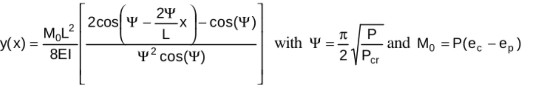
Structural failure is assumed to occur when the load applied on the wall exceeds the buckling load. The stud’s out-of-plane deflection is estimated using the theory of elasticity. The deflection of the stud, as predicted for a hinged-hinged eccentric column, can be calculated by considering the stud as a beam-column structure. The out-of-plane deflection, y, at any height x on the stud at any time, is:
Ψ Ψ Ψ − Ψ− Ψ = ) cos( ) cos( x L 2 cos 2 EI 8 L M ) x ( y 2 2 0 with cr P P 2 π = Ψ and M0 =P(ec −ep) [2]
where L is the length of the stud (mm), ec is the eccentricity of the centroid of the resisting member
(mm), and ep is the applied load eccentricity (mm). The maximum deformation occurs at mid-height.
Comparison of model predictions with experimental data
In this paper, only the fire resistance test for assembly No. 23 was used to evaluate the predictions by the fire resistance model. Details of the assembly are shown in Table 1. The predictions of time-temperature curves generated by the heat transfer have been used to calculate the reduction in load-carrying capacity of the studs and the degradation in the modulus of elasticity, which was assumed to be equal to 7000 MPa at ambient temperature. Temperatures on the unexposed sides did not reach the insulation failure criterion, as the assembly failed by structural instability at 36 min. Table 2 summarizes the model predictions and experimental results. The model predicts conservatively the onset of charring, with a difference of about 10%.
Table 2. Comparison between tests results and model predictions Onset of Char (min) Insulation Failure (min) Structural Failure (min) Test No.
Test Model Difference Test Model Test Model Difference
23 19.0 17.0 10% N/A 48.0 36.0 33.0 8%
To measure the performance of the structural response model, the theoretical predictions of the structural fire resistance and deflection at mid-height are evaluated. Figure 3a illustrates the critical elastic buckling load versus time as predicted by the structural response sub-model. The fire resistance decreases with increasing time because the value of the modulus of elasticity decreases with time and the cross-section of the studs reduces after charring. The intersection of the horizontal line, at the level of the applied load (8.45 kN), with the elastic buckling-curve, represents the theoretical time to structural failure of the wall. The time is 33 min for the assembly, while the time to structural failure measured experimentally is 36 min. Therefore, the model predictions are very close to the test results, with the analytical time to structural failure underestimated by 8%. Table 2 also shows a summary of the model predictions and experimental results for the test.
The maximum mid-height deflections are also plotted versus time for both the analytical predictions and the test results (see Figure 3b). As shown in this figure, the deflection is very small in the first 30 min. After this, the model predictions and the test measurements start increasing at a faster rate. The rate of increase in the model predictions is similar to that of the test results. The rate in the model, however, starts a few minutes later. The model slightly overestimates the deflection at 33 min. The fire resistance model described above is based on the elastic buckling theory of a single stud. However, in a wall assembly, failure of one stud may not mean failure of the whole wall system. This is due to the possible redistribution of the load to the other studs, which did not fail, especially to those at the ends. It is sometimes suggested to cut the end studs so that they do not contribute to the load and a realistic comparison may be made with model predictions that are based on the load on a
single stud. In the tests presented here, the end studs were not cut (contributed to the load) and consequently we need to find another alternative to treat the walls as assembly systems. To achieve this, the following method was used:
1. The wall assemblies tested contain 10 studs each and 2 vertical GB joints (for direct application):
• 2 studs where joints open
• 6 studs where joints do not open
• 2 end studs
2. Run the fire resistance model with 3 cases:
• Simulation with joint opening (failure will occur first)
• Simulation without joint opening (failure will occur next)
• Simulation with conditions kept as ambient (failure will not occur)
3. Calculate the total assembly resistance by adding the resistance from all cases with the appropriate coefficients (stud number) at each time step as: 2 x case1 + 6 x case2 + 1 x case3 4. Compare the total resistance to the total applied load at every time step.
5. Determine the fire resistance when the load becomes higher than the buckling resistance.
Fire Resistance vs Time
0 2000 4000 6000 8000 10000 12000 14000 16000 18000 0 5 10 15 20 25 30 35 40 Time (min) Load (N) Applied Load
Maximum Deflection vs Time
-20 0 20 40 60 80 100 120 140 160 180 0 5 10 15 20 25 30 35 40 Time (min) Deflection (mm) Model prediction Experimental data (a) (b)
Figure 3. Fire resistance determination and deflection comparisons.
Figure 4 shows the buckling resistance of Test No. 23 vs. time, calculated based on the method described above. As illustrated in the figure, when the first 2 studs fail (at 33 min), the wall can still resist for 3 more minutes as the load is redistributed and being resisted by the studs that have not reached failure. The method, however, assumes that the end studs remain at ambient temperatures, which may not be realistic. Based on this, it can be concluded that using a model based on a single stud, as opposed to a complete system, may provide reasonable and conservative predictions.
Fire Resistance vs. Time (System)
0 20000 40000 60000 80000 100000 120000 140000 160000 0 10 20 30 40 50 60 Time (min) Load (N) Applied load
SUMMARY, CONCLUSIONS AND FUTURE WORK
To evaluate the impact of changes in code requirements and building construction materials, an extensive experimental program has been undertaken to investigate the effects of a number of design parameters including the types of insulation, resilient channels, gypsum board thickness, number of gypsum board layers, stud arrangements, stud spacing, type of framing and shear membrane on the fire performance of wall assemblies. The results have shown that the main factors that affected the performance of stud-wall assemblies are the type of insulation, stud spacing, the number of gypsum board layers, and the addition of a shear membrane. The data gathered from this study was used to produce key design trends, to propose generic ratings for possible incorporation in the appendices of the National Building Code of Canada, and to develop fire resistance models for wood- and steel-stud wall assemblies. This information is of great benefit to practitioners, builders and regulators in choosing suitable assemblies for their design. In particular, a wood-stud wall fire resistance model, developed with the wood industry, was presented and validated against the results of a test. As a next step, the model will be validated against more experimental data that include exposure to both standard and non-standard fire.
ACKNOWLEDGEMENTS
This research was funded by NRC and industry partners that included the Canadian Wood Council, Canadian Home Builders Association, Canadian Sheet Steel Building Institute, Forintek Canada Corp., Owens-Corning Canada, Roxul Inc., Gypsum Manufacturers of Canada. The authors are grateful to John Latour, Patrice Leroux, Roch Monette and Jocelyn Henrie for assisting in constructing the assemblies and conducting the tests.
REFERENCES
1
Canadian Commission on Building and Fire Codes (1995), National Building Code of Canada, Institute for Research in Construction, National Research Council of Canada, Ottawa, Canada.
2
CAN/ULC-S101-M89 (1989) Standard Methods of Fire Endurance Tests of Building Construction and Materials, Underwriters' Laboratories of Canada, Scarborough, Canada.
3
M. A. Sultan and G. D. Lougheed, Results of Fire Resistance Tests on Full-Scale Gypsum Board Wall Assemblies, Internal Report (in press), Institute for Research in Construction, National Research Council, Ottawa, Canada
4
V.K.R. Kodur, M.A. Sultan and E.M.A. Denham, Temperature Measurements in Full-Scale Wood Stud Shear Walls, Internal Report No. 729, Institute for Research in Construction, National Research Council, Ottawa, Canada, (1996).
5
V. K. R. Kodur, M. A. Sultan, J.C. Latour, P. Leroux and R.C. Monette, Experimental Studies on the Fire Resistance of Load-Bearing Steel Stud Walls, Internal Report (in press), Institute for Research in Construction, National Research Council, Ottawa, Canada.
6
H.Takeda and J.R. Mehaffey, WALL2D: A Model for Predicting Heat Transfer through Wood-Stud Walls Exposed to Fire,” Fire and Materials, 22: 133-140, 1998.
7
E.L. Schaffer, Elevated Temperature Effect on the Longitudinal Mechanical Properties of Wood, Ph.D. Thesis, Department of Mechanical Eng., Univ. Wisconsin, Madison, USA, 1970.