DYNAMICS AND CONTROL OF THE SPACE SHUTTLE BASED KINETIC ISOLATION TETHER EXPERIMENT
by
Captain Mark William Stephenson
B.S., United States Military Academy (1980) SUBMITTED TO THE DEPARTMENT OF AERONAUTICS AND
ASTRONAUTICS IN PARTIAL FULFILLMENT OF THE REQUIREMENTS FOR THE DEGREES OF
ENGINEER IN AERONAUTICS AND ASTRONAUTICS AND
MASTER OF SCIENCE IN AERONAUTICS AND ASTRONAUTICS at the
MASSACHUSETTS INSTITUTE OF TECHNOLOGY MAY, 1988
Mark William Stephenson, 1988 Signature of Author
Department of Aeronautics and Astro autics, May 6, 1988 Certified
by---Edward V. Bergmann Thesis Supervisor, C. S. Draper Lab.,Inc. Certified by
Professor Richard H. Battin Adjunct Professor of Aeronautics and Astronautics Certified by
Professor alter M. Hollister Professor of Aeronautics and Astronautics Certified by
Professor Andreas von Flotow Assistant Professor of Aeronautics and Astronautics Accepted by
Accepted by--- , profetde VF~f---6-,fC v Harold Y. WachmanHarold Y. Wachman Chairman, Departmental Graduate Committee
1ero
TF M1-1-06
I hereby assign my copyright of this thesis to the Charles Stark Draper Laboratory, Inc., Cambridge,
Massachusetts.
Mark Willi Stephenson
Permission is hereby granted by the Charles Stark Draper Laboratory, Inc., to the Massachusetts Institute of Technology to reproduce any or all of this thesis.
DYNAMICS AND CONTROL OF THE SPACE SHUTTLE BASED
KINETIC ISOLATION TETHER EXPERIMENT
by
CAPTAIN MARK WILLIAM STEPHENSON
Submitted to the Department of Aeronautics and Astronautics on May 6, 1988, in partial fulfillment of the requirements for the Degrees of Engineer in Aeronautics and Astronautics
and Master of Science in Aeronautics and Astronautics ABSTRACT
The Kinetic Isolation Tether Experiment is a proposed Space Shuttle flight demonstration experiment tentatively
scheduled for launch in the mid 1990's. Attitude control of a
1000 kg tethered subsatellite via a movable tether attachment
point is the primary focus of this investigation; however, many secondary issues pertaining to the overall mission are
also investigated.
The investigation consists of six major parts:
1) Consolidating and selecting mission equipment
2) Discussing the proposed tether deployment strategies
3) Deriving equations of motion for a rigid body spacecraft
perturbed by external torques and two mobile masses 4) Designing the subsatellite's attitude control system
5) Building a numerical simulation of the Shuttle Tether
-Subsatellite orbital system
6) Experimenting with the numerical simulation to evaluate the
subsatellite's attitude control system and investigate Space Shuttle attitude control options
Three Proportional-Integral-Derivative control loops are developed for subsatellite attitude control. The yaw loop controls a reaction wheel while the pitch and roll loops
control the movable tether attachment point. The simulations compare the effects of loop gain, low pass filtering, and
integral feedback on subsatellite attitude errors. Space Shuttle free drift equilibrium attitudes, Local-Vertical-Local-Horizontal attitude holding, and holding of equilibrium attitudes are compared on the basis of induced tether
disturbances and attitude control fuel efficiency.
This study reinforces the feasibility of the proposed flight demonstration experiment and develops specific
recommendations to improve the mission. Thesis Adviser: Dr. Richard H. Battin
Title: Charles S. Draper Adjunct Professor of Aeronautics and Astronautics
BIOGRAPHY
OF
MARK WILLIAM STEPHENSON CAPTAIN, U.S. ARMY
Captain Mark W. Stephenson was born in Cincinnati, Ohio, on 12 May 1958. He graduated with honors from the United States Military Academy in May of 1980 and was
commissioned a Second Lieutenant in Military Intelligence with orders to attend Flight Training. While a Cadet, he majored in Mathematics, completed Airborne Training,
commanded a company, and was a semifinalist in the Rhodes Scholarship competition.
He graduated with honors from the Military Intelligence Officer Basic Course and the Tactical
Surveillance Officer Course at Fort Huachuca, Arizona, on 12 September 1980 and 6 February 1981, respectively.
In rapid succession, he completed the Initial Entry Rotary Wing Aviator Course on 31 October 1981, Fixed Wing Multi-Engine Qualification Course on 24 March 1982, and OV-1D (Mohawk) Surveillance Airplane Aviator
Qualification Course on 25 May 1982 at Fort Rucker, Alabama.
Upon returning to Fort Huachuca in June 1982, 1LT Stephenson completed the OV-1D (Mohawk) Surveillance Airplane Aviator Combat Skills Qualification Course on 9 July 1982.
After completing six years of intensive military education, 1LT Stephenson was assigned to the 15th Military Intelligence Battalion (Aerial Exploitation),
Fort Hood, Texas, on 15 July 1982. During the first eight months of his assignment, he served as the Flight Operations Officer and Imagery Interpretation Platoon Leader of the Aerial Surveillance Company. He served as the Executive Officer of the Aerial Surveillance Company from March to November of 1983 followed by service as the Battalion Executive Officer from 15 November 1983 until his departure from Fort Hood on 10 December 1984.
On 31 May 1985, CPT Stephenson graduated with honors from the Aviation Officer Advanced Course at Fort Rucker, Alabama.
He served as the Mission Operations Officer of the 3rd Military Intelligence Battalion, Camp Humphreys, Republic of Korea, from June 1985 to May 1986.
Since June 1986, CPT Stephenson has been a Graduate Student pursuing the degrees of Engineer in Aeronautics and Astronautics and Master of Science in Aeronautics and Astronautics at the Massachusetts Institute of Technology with full funding under the United States Military
Academy Top Five Percent Program. Upon completion of his studies in May of 1988, CPT Stephenson will instruct
Aerospace Engineering at the United States Military Academy, West Point, New York for a period of three years.
MILITARY SCHOOLS ATTENDED: (in chronological order) United States Military Academy
Airborne School
Military Intelligence Officer Basic Course Tactical Surveillance Officer Course
Initial Entry Rotary Wing Aviator Course Fixed Wing Multi-Engine Qualification Course OV-1D (Mohawk) Aviator Qualification Course
OV-lD (Mohawk) Aviator Combat Skills Qualification course U.S. Air Force Water Survival Training Course
Military Airlift Command Planners Course
U.S. Air Force Strategic Mobility Planners Course Aviation Officer Advanced Course
Combined Arms and Services Staff School
US DECORATIONS:
2 - Meritorious Service Medals 1 - Army Commendation Medal 1 - Army Achievement Medal 1 - Army Superior Unit Award 1 - Army Service Ribbon
1 - Army Overseas Ribbon
AIRCRAFT QUALIFICATIONS: APPROX. HRS. FLOWN:
TH-55 Training Helicopter 50
UH-1H Utility Helicopter 163
T-42 Multi-Engine Training Airplane 60
OV-1D Combat Surveillance Airplane 777
ACKNOWLEDGEMENTS
I would like to thank the following friends and
associates for their contributions to this document. Professors Richard H. Battin, Walter M. Hollister, and Andreas von Flotow for their excellent classroom instruction that prepared me for this endeavor. Their sound advice and guidance as members of the thesis
committee was greatly appreciated and I am proud to have their autographs on my title page.
Mr. Edward V. Bergmann, Thesis Supervisor, C. S. Draper Laboratory, for his initial suggestion of the thesis topic and his continued guidance during this effort.
Mr. Chris C. Rupp, Contract Administrator, NASA
Marshall Space Flight Center, for funding of the research and his assistance in making contacts and providing
background information that shaped the focus of this thesis.
Mr. Bruce A. Persson, Technical Advisor, C. S. Draper Laboratory, for the quality of his work prior to my involvement in the project and the thoroughness he displayed during the transition of this project to my control.
Major W. Neil McCasland, United States Air Force, for introducing me to Ed Bergmann during my search for a thesis topic and providing technical guidance concerning the design of the subsatellite attitude control system.
Mr. Larry G. Lemke, NASA Ames Research Center, for providing technical information concerning his research on the Kinetic Isolation Tether Experiment.
Professor J. David Powell, Mr. Xiaohua He, and Mr. Robert Schoder of Stanford University for providing technical information concerning their continuing
investigation into the Kinetic Isolation Tether Experiment.
Mr. Joseph A. Carroll, Energy Sciences Laboratory, Inc., for providing technical information concerning his Small Expendable-tether Deployment system and technical discussions concerning tether selection and deployment strategies for the Kinetic Isolation Tether Experiment.
Mr. Scott Lambros, Spartan Office, Goddard Space Flight Center, for providing assistance and references concerning the Spartan spacecraft.
Mr. Steve Pateuk, Design Components, Inc., for
providing technical information and assistance concerning their HM-2424 positioning table and its accessories.
Last but not least,
Debra A. N. Stephenson, my wife, for her support during this project and her assistance in preparing the final document.
This report was prepared under contract NAS8-36602 with the National Aeronautics and Space Administration.
Publication of this report does not constitute approval by the Charles Stark Draper Laboratory or NASA of the findings or conclusions contained herein. It is published solely for the exchange of ideas.
TABLE OF CONTENTS
Page INTRODUCTION ... . .. ..
1.1 General Mission Description . ..
1.2 Background . ... . . . . .
1.3 Thesis Overview ... . . . . . .
MISSION EQUIPMENT. .. . . . . . . .
2.1 Introduction . . . . . . . . . . . .
2.2 Spartan Service Module . . . . . . .
2.3 KITE Spacecraft .. . . . . . . .
2.3.1 General. . . . . . . . . .
2.3.2 Reaction Wheel . . . . . . . .
2.3.3 X-Y Stage . . . . . . . .
2.4 Spartan Flight Support Structure (SF
2.5 Small Expendable-tether
Deployment System (SEDS) ...
2.6 Mounting of SEDS to SFSS . ... 2.7 Tether . . . ..
2.8 Space Shuttle . . . . . .
2.8.1 Reaction Control System (RCS)
2.8.2 Payload Capabilities . . . . . . . 16 . . 16 . 18 . . 20 .. 23 . 23 . 23 . . 27 .. 27 . 29 32 'SS). 35 . 36 .. 38 .. 40 . . 41 SPACECRAFT DEPLOYMENT . . . . . . . . . . . 3.1 Introduction . . . . . . . . . . . . . . 3.2 Deployment Considerations. . . . . . .
3.3 A Nominal Deployment Scenario . . . . .
3.4 A Mathematically Simplified
Deployment Model . . . . . . . . . . . .
3.4.1 Modeling Assumptions . . . . . . .
3.4.2 Defining the LVLH Reference Frame 3.4.3 Coordinate Frame Equations
of Motion . . . . . . .
3.4.4 Circular Orbit Approximation . . .
3.4.5 Motion Equations About the
System Mass Center . . . . . . . .
3.4.6 Constraints and Initial Conditions 3.4.7 SEDS Friction Function . . . . . .
3.4.8 Estimating Initial Tension
Requirements . . . . . . . . . . .
3.5 Energy Sciences Laboratory
Deployment Simulation . . . . . . . . .
Chapter
41 43 46 46 47 48 48 49 50 50 51 51 55 57 59 60 . . . .Chapter
SUBSATELLITE EQUATIONS OF MOTION . . .
4.1 Introduction . . . . . . .
4.2 Translational Equation of Motion 4.3 Rotational Equation of Motion .
4.4 Tether Torques . . . . . . . .
4.5 Aerodynamic Torques ... 4.6 Gravity Gradient Torques . . . .
4.7 Radiation Pressure Torques .
4.8 Reaction Wheel Torques . . . . .
4.9 Mobile Mass Torques . . .... 4.10 Isolation of Subsatellite Angular
Acceleration . . . . . . . . . . . .
4.11 Spacecraft Excitation of the Tether .
KITE CONTROLLER . . . . . . . . . . . .
5.1 Introduction . . . . . . . . . . . . 5.2 Yaw Control
5.2.1 Reaction Wheel Torque Equation 5.2.2 Yaw PID Control Loop . . . . .
5.2.3 Selecting PID Compensation Constants . . . . . . . . . .
5.2.4 Modified PID Yaw Control Loop 5.3 Review of Pitch and Roll Control
5.3.1 Review of Pitch and Roll
Control Geometry . . . . . . .
5.3.2 Review of Pitch and Roll
Control Laws . . . . . . . . .
5.3.3 Review of Pitch and Roll
Control Stability . . . . . .
5.4 Pitch Control . . . . . . . . . . .
5.4.1 PID Pitch Control . . . . . .
5.5 Roll Control . . . . . . . . . . .
5.5.1 PID Roll Control. . . . .
5.6 Linearized Stability Analysis . . .
5.6.1 Stability of the Linearized
PD Loop ...
5.6.2 Stability of the Linearized PID Loop . . . . . . . . . .
KITE NUMERICAL SIMULATION . . . . . .
6.1 Introduction . . . . . . . . . .
6.2 Simulation Evolution . . . . . .
6.3 Space Shuttle Simulation . . . .
6.4 Control Dynamics Company
Tether Simulation . . . . . . . .
6.5 KITE Spacecraft Simulation . . .
62 62 63 64 65 66 69 72 76 77 . 82 . 87 90 90 91 91 92 94 95 97 . . 97 . . 99 .101 . . 103 .. 103 . . 105 .. 105 . . 108 S. 109 . . 113 117 . . . 117 118 119 120 S. . 121 Page . . . .• . .• . • . .• . .•
Chanter
7 EXPERIMENTAL RESULTS . . . . . . . . . . . 125
7.1 Introduction . .... . . . . . . 125
7.2 Evaluating Unfiltered Proportional-Derivative Controllers . ... 127
7.3 Evaluating Filtered Proportional-Derivative Controllers . . ... . 131
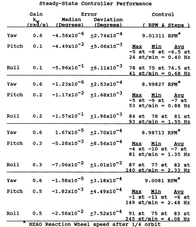
7.4 Evaluating Filtered Proportional-Integral-Derivative Controllers . . . 136
7.5 Mobile Mass Induced Attitude Error . . 140
7.6 KITE SpacecraftACM Compensation . . . 144
7.7 Investigating Usage of the HMP-2424 Precision Positioning Table . .... 148
7.8 Investigating the Effects of Tether Length on Controller Performance . . . 151
7.9 Investigating the Effects of Tension Measurement Errors on Controller Performance . . . ... 154
7.10 Investigating the Effects of X-Y Stage Orientation . ... 156
7.11 Investigating the Effects of Vertical Separation Between the Attach Point Plane of Motion and the X-Y Plane Containing the Spacecraft's Mass Center . . . . . . . 158
7.12 Investigating the Effects of Mass Center Uncertainties . ... ... . . 161
7.13 Investigating the KITE Controllers Off-Nominal Turn-On Performance . . . 162
7.14 Investigating Space Shuttle-Tether Attachment Point Effects . . . . . . . 167
7.14.1 Introduction . ... 167
7.14.2 Holding the Shuttle X-Y Plane Perpendicular to the Local Vertical . . . . . . . . . . . 167
7.14.3 Holding Space Shuttle Tethered Equilibrium Attitudes . .... 172
7.15 Near-Worst-Case Testing of the Recommended Mission Profile . . . . . 179
8 CONCLUSIONS . ... 190
8.1 Summary .
. . . .
... .. 1908.2 Recommendations . . . . . . . . . . . . 190
8.3 Suggestions for Further Research . . . 193
9 BIBLIOGRAPHY . . . . . . . . . . . . . . . 195 Page
LIST OF TABLES
Table Page
2-1 KITE Mission Specific Hardware Added to
the Spartan Service Module ... 27
2-2 Sperry P80-2 Reaction Wheel Specifications. 30 2-3 Sperry HEAO Reaction Wheel Specifications . 31
2-4 Tether Properties for KITE . ... 40
6-1 KITE Spacecraft Point Mass Model . . . . . 121
6-2 KITE Spacecraft Aero/Radiation Surfaces . 122
7-1 Unfiltered Proportional-Derivative Controller Performance . . . . . . . . . . 130 7-2 Filtered Proportional-Derivative Controller Performance . . . . . . . . . . 135 7-3 Filtered Proportional-Integral-Derivative Controller Performance . . . . . . . . . . 139
7-4 Parameters of the Recommended Mission
Profile . . . 179
7-5 Parameters Used in the Near-Worst-Case
Simulation of the Recommended Mission
LIST OF FIGURES
Figure Page
1-1 Orbital View of the Kinetic Isolation
Tether Experiment . ... 17
2-1 Spartan 200 Service Module . ... 24
2-2 KITE Spacecraft Configuration . ... 28
2-3 Top View of KITE Spacecraft . ... 29
2-4 KITE Spacecraft X-Y Stage / DCI HM-2424 . 33 2-5 Spartan Flight Support Structure (SFSS) and Spartan Service Module . . . . . . . . 36
2-6 Small Expendable-tether Deployment System (SEDS) . . . . . . . . . . . . . . . 37
2-7 Small Expendable-tether Deployment System (SEDS) Mounted Directly to a Spartan Flight Support Structure . ... . 39
2-8 Small Expendable-tether Deployment System Mast Mounted to a Spartan Flight Support Structure . ... 39
2-9 Space Shuttle Payload Bays. ... . . . 43
2-10 Spartan On Board STS Mission 51-G . .... 45
3-1 Nominal Orientation for KITE Deployment . 52 3-2 Energy Sciences Laboratory Simulation Results for 1 km KITE Deployment . . . . . 60
Figure Page 5-1 Initial PID Yaw Loop Concept ... 92
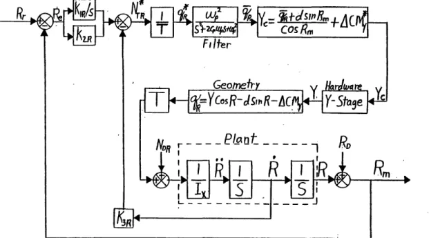
5-2 Modified PID YAW Loop ... 96
5-3 Attitude Control Geometry . ... 97 5-4 KITE Dynamic System Block Diagram . .... 99 5-5 KITE Dynamic System With PD Controller . 100 5-6 Simplified KITE Controller Block Diagram . 101
5-7 Stanford Attitude Root Locus Comparison . 102
5-8 Pitch Control PID Loop Block Diagram . . . 104
5-9 Roll Control PID Loop Block Diagram . . . 106
5-10 Linearized PID Loop Block Diagram . . .. 109
5-11 PD Loop Generalized Attitude Root Locus . 112
5-12 PID Loop Generalized Attitude Root Locus . 115
6-1 KITE Simulation Application of
Tether Tension .. ... .. . . . . 123 7-1 Unfiltered Proportional-Derivative
Controller Performance . . . . . . . . . . 128 7-2 Unfiltered Proportional-Derivative
Controller Workload . ... . 129
7-3 Filtered Proportional-Derivative Controller Instability With kw = 0.5 Radians/Second . 132 7-4 Filtered Proportional-Derivative Controller
Performance With kw = 0.2 Radians/Second . 133 7-5 Proportional-Derivative Controller Workload
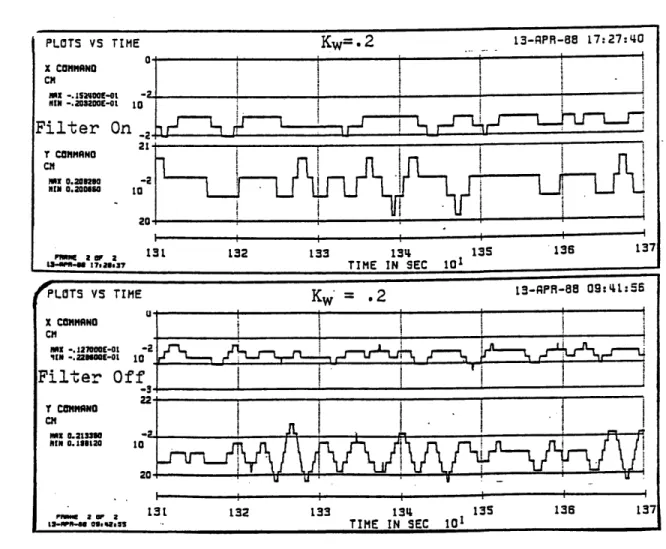
Reduction Due to Low-Pass Filtering . . . 134
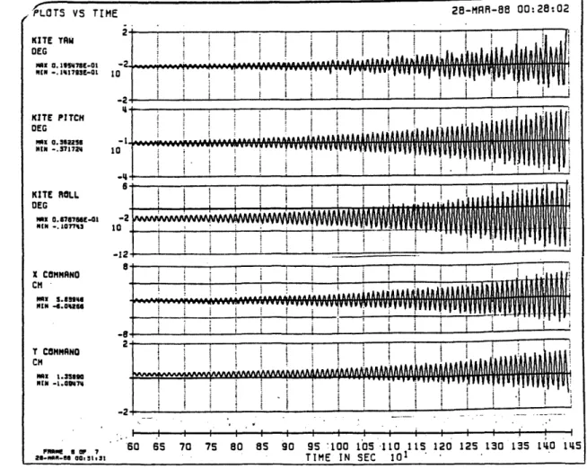
7-6 Filtered Proportional-Integral-Derivative Controller Performance With
kw = 0.2 Radians/Second . ... 137
7-7 Effects of Integral Feedback on
Controller Workload . . . . . . . . . . . 138
Figure Page
7-8 Mobile Mass Induced Attitude Errors . . . 140
7-9 Reoriented X-Y Stage Effects on Mobile
Mass Induced Errors . . . . . . . . . . . 142
7-10 Mass Center Compensation Geometry . . . . 144
7-11 ACM Compensation Effect on Controller
Turn-On Performance . . . . . . . . . . . 146
7-12 ACM Compensation Effect on Controller
Workload . . . . . . . . . . . . . . . . . 147
7-13 Comparison of Controller Performance:
5-Pitch vs 10-Pitch Lead Screws . . . . . 149 7-14 Comparison of Controller Workload:
5-Pitch vs 10-Pitch Lead Screws . . . . . 150
7-15 Comparison of PID Controller Performance
for 3 and 5 km Tethered Operations . . . . 152
7-16 Comparison of PID Controller Travel
for 3 and 5 km Tethered Operations . . . . 153
7-17 Comparison of the Effects of Tension
Measurement Errors on the KITE Controller. 155
7-18 Comparison of Controller Workload for Two
Different X-Y Stage Orientations . .... 157
7-19 KITE Controller Performance Degradation
Due to Vertical Displacement of the
Attachment Point from the Mass Center . . 159
7-20 KITE Controller Workload Increase Due to
Vertical Displacement of the Attachment
Point from the Mass Center . . . . . . . . 160
7-21 KITE Controller Off-Nominal Turn-On
Performance . . . . . . . . . . . . . . . 164
7-22 KITE Controller Turn-On Performance With
Immediate Large Angle Rotations . .... 166
7-23 Shuttle's X-Y Plane Maintained
7-24 Shuttle Behavior with 5 km Tether
Attached at Forward Edge of Bay 5 . . . . 171
7-25 Approximate Shuttle Tethered
Equilibrium Attitude . ... 172
7-26 Shuttle's Tethered Equilibrium Attitude
With SEDS Mounted on a Six-Foot Mast . . . 176
7-27 Digital Autopilot Maintaining Shuttle
Tethered Equilibrium Attitude With SEDS
on a Six-Foot Mast, and SFSS in Bay 5 . 178 7-28 KITE Controller Performance: First Ten
Minutes for a Near-Worst-Case Simulation
of the Recommended Mission Profile . . . . 184
7-29 Space Shuttle Performance: First Ten Minutes for a Near-Worst-Case Simulation
of the Recommended Mission Profile . . . . 185
7-30 KITE Controller Performance: Ten Minutes
Near the End of the First Orbit for a Near-Worst-Case Simulation of the
Recommended Mission Profile . . . . . . . 186
7-31 Space Shuttle Performance: Ten Minutes Near the End of the First Orbit for a Near-Worst-Case Simulation of the
Recommended Mission Profile . . . . . . . 187
7-32 KITE Controller Performance: Ten Minutes Near the End of the Second Orbit for a Near-Worst-Case Simulation of the
Recommended Mission Profile . . . . . . . 188
7-33 Space Shuttle Performance: Ten Minutes Near the End of the Second Orbit for a Near-Worst-Case Simulation of the
Recommended Mission Profile . . . . . . . 189
15
CHAPTER 1 INTRODUCTION
1.1 GENERAL MISSION DESCRIPTION
The Kinetic Isolation Tether Experiment (KITE) is a proposed Space Shuttle flight experiment intended to
demonstrate the feasibility of providing attitude control to a space platform by varying the attachment point of a tether.1 Moving this point will cause the tether tension
force to be offset from the platform center of mass, thus producing an external torque. The general experimental plan is to deploy a modified SPARTAN 1 spacecraft
(approx. 1053 kg / 2320 lb) via a viscoelastic tether in a gravity gradient stabilized orientation (i.e., straight up or straight down in the geocentric orbiting reference
frame). The nominal separation distance will be selected to be in the 1 to 5 kilometer range and, if operational considerations permit, will be varied during the course of the experiment. This separation distance will allow low-power, low-bandwidth RF communications with the
orbiter to permit uninterrupted real-time interaction by 1 W. A. Baracat and C. L. Butner, "Tethers in Space
Handbook", Contract No. NASW-3921, August 1986, p. 10.
the Mission Specialist on the orbiter aft flight deck. A microprocessor and X-Y translation mechanism will move the tether attachment point to control the spacecraft's pitch and roll attitude while a reaction wheel controls the spacecraft's yaw attitude. After approximately 15 hours of experimentation, the tether will be cut at both ends and the Shuttle will fly a rendezvous maneuver to retrieve the KITE spacecraft.
This project is currently in the demonstration mission definition phase; however, it will progress to the contract and development phase during the Summer of
1988. Figure 1-1 depicts the orbital view of the Kinetic Isolation Tether Experiment deployed downward along the local vertical.
Figure 1-1. Orbital View of the Kinetic
1.2 BACKGROUND
In recent years, interest in using a tether to
assist platform pointing has grown. J. A. Carroll first proposed the utilization of tether tension to assist platform pointing.2 He suggested moving weights within the instrument platform to achieve mass center offsets with respect to the tether attachment point, thus
producing torques. L. G. Lemke expanded Carroll's idea by proposing that the entire platform be used as a
movable weight by moving the tether attachment point.3 NASA's Ames Research Center, with a group of Italian researchers, initiated the Kinetic Isolation Tether Experiment (KITE) definition study shortly thereafter.
By January 1986 L. G. Lemke of NASA's Ames Research Center and J. D. Powell and X. He of Stanford University had completed the initial laboratory modeling of the KITE spacecraft. Their research included a refined definition of the experiment, investigation of pitch-roll control laws, and the preliminary layout of the KITE spacecraft reference configuration.4 In September 1986 this same research team published a paper entitled "Attitude
2 J. A. Carroll, "Small Expendable Deployment System," SBIR Phase 2 Contract No. NASA 8-35256, March 1985. 3 L. G. Lemke, "A Concept for Attitude Control of a Tethered Astrophysical Platform," Presented at AIAA Guidance and Control Conference, Paper No. 85-1942-CP, August 1985, p. 1.
4 D. Powell, L. Lemke, and X. He, "Final Report on an Investigation of the Kinetic Isolation Tether
Control of Tethered Spacecraft" which supported the feasibility of achieving attitude accuracy in the range of one arcsecond.5 In their annual report, submitted February 1987, Powell, He, and Schoder reported that they had conducted a laboratory simulation with analysis that supported the feasibility of attaining sub-arcsecond pointing control about three axes with the proposed pitch-roll control system.6
After reviewing the promising results of the Ames-Stanford efforts, Chris Rupp of NASA's Marshall Space Flight Center contracted Charles S. Draper Laboratory to evaluate the feasibility and contribute to the
development of a proposed Shuttle-based flight experiment.
5 D. Powell, L. Lemke, and X. He, "Attitude Control of Tethered Spacecraft," Presented at NASA/AIAA/PSN
International Conference on Tethers in Space, September 1986, p. 1.
6 D. Powell, X. He, and R. Schoder, "Annual Report on Kinetic Isolation Tether Experiment", Grant No. NCC2-389, February 1987, p. 2.
1.3 THESIS OVERVIEW
As with any investigation, this thesis begins with a review of the literature to consolidate the contributions of prior researchers. Vast numbers of publications have dealt with space tethers; however, few have addressed concepts similar to the Kinetic Isolation Tether
Experiment. Conducting research on this evolving concept is a two edged sword: There are many opportunities to contribute to the concept; however, one's findings are based upon the current form of an evolving mission
profile. With that in mind the reader should understand that the primary goal of this thesis is to evaluate the
feasibility of the broader experimental concept and identify issues rather than focusing on the current
mission profile. Contributing to the mission profile by recommending hardware and operational procedures is an important but secondary goal of this investigation.
That argument sounds reasonable until one realizes that it's very difficult to evaluate broad experimental issues without specifying hardware or its operational employment. In fact, the equations of motion of the tethered spacecraft depend upon hardware selection.
Therefore, hardware issues are discussed in Chapter 2 of this thesis.
Chapter 3 discusses the deployment of the tethered
considerations applicable to the KITE deployment. Evaluation of the deployment issue was limited to
discussions with other contractors due to the proprietary restrictions of the small Expendable-tether Deployment System. The deployment issue should be further
investigated when the deployer's performance and operational restrictions are disclosed.
Chapter 4 develops the equations of motion
applicable to the tethered spacecraft. These equations form the basis of the simulation and are central to KITE spacecraft control issues.
Chapter 5 describes the evolution of the
subsatellite's attitude control scheme from its initial concept to its present form. This chapter focuses on the development of a Proportional-Integral-Derivative
reaction wheel control law to maintain yaw attitude and two Filtered-Proportional-Integral-Derivative tether attachment point control laws to maintain pitch and roll attitude. Presentation of linearized root locus
stability analyses for both
Filtered-Proportional-Derivative and Filtered-Proportional-Integral-Filtered-Proportional-Derivative controllers concludes this chapter.
Chapter 6 discusses the VAX based FORTRAN simulation of the KITE mission. The simulation includes attitude dynamics and control of the Space Shuttle as well as the KITE spacecraft. Environmental torques such as
aerodynamic, solar pressure, gravity gradient, and third body perturbations have been modeled as well as the more dominant control torques. The tether model includes
longitudinal and lateral modes utilizing a 19 node finite differencing method. Bending stiffness and end-body
excitation of the tether have been included. Chapter 7 provides the results of extensive
simulations. Each series of simulations investigates a question of importance to the KITE mission. Most of the questions fall into one of two broad categories. The
first is Space Shuttle attitude control for various
autopilot modes, attitudes, and tether attachment points. The second is subsatellite controller performance under various control schemes, tether lengths, and initial conditions. A recommended mission profile evolves from the experimental results. Chapter 7 ends with a near-worst-case, two-orbit simulation of the recommended mission profile.
Chapter 8 summarizes the issues, reviews recommended modifications, and suggests opportunities for further research that may contribute to the common goal: safe and efficient conduct of the Kinetic Isolation Tether Experiment.
CHAPTER 2 MISSION EQUIPMENT
2.1 INTRODUCTION
This chapter focuses on the hardware applicable to the Kinetic Isolation Tether Experiment. It summarizes information gathered from published articles and
reference manuals as well as telephone conversations with experts on each piece of equipment. The material
presented discusses basic equipment characteristics as they pertain to KITE. References are provided for the reader desiring greater detail.
2.2 SPARTAN SERVICE MODULE7
The Goddard Space Flight Center Spartan is a free-flying, reusable, scientific spacecraft carried to orbit aboard the Space Shuttle. Lemke, Powell, and He
recommended Spartan 1 for the Kinetic Isolation Tether Experiment due to its reliability and versatility.8
7 All specifications and figures pertaining to the
Spartan spacecraft have been obtained from the National Aeronautics and Space Administration, "Spartan Capability Statement" and "Spartan Capability Statement for the
Class 200 Carrier System".
Recently, an improved version of the spacecraft, Spartan 200, has been developed. Many enhancements have been added including increased experimental power availability and payload capacity. It appears that both versions
would be acceptable for the KITE mission as currently envisioned. Final selection may depend upon spacecraft availability and experimental payload or power
requirements.
The Spartan Service Module is the portion of the spacecraft that will be used in the KITE experiment (see
figure 2-1).
SUBSYSTEM
Both Spartan 1 and Spartan 200 Service Modules are rectangular with dimensions of 1.0 by 1.3 by .86 meters. One half of the service module's internal volume is
occupied by the support systems. These support systems include payload function control, power, Attitude Control Electronics (ACE's) and sensors, thermal control, and pneumatics. Some support system components important to the KITE are as follows:
1) Two large batteries and power conditioning equipment providing 30 KWH of 28 VDC for the
Spartan 200 and 8 KWH of 28 VDC for the Spartan 1 2) A Bell & Howell Mars 1400 high capacity tape
recorder
3) A Microprocessor sequencer and attitude controller
4) Two Teledyne SDG-4, two-degree-of-freedom, Tuned Restraint Integrating Gyros (TRIG) performing with drift < 0.1 degree/hour
5) A Star Tracker with + 1 arc-min, 8 degree FOV 6) Solar sensors
7) A cold-gas thruster system (Nitrogen, Argon, or Freon) capable of providing angular
accelerations, but not translation
The Spartan has many capabilities; however, one important capability required for the KITE mission is absent. Neither Spartan 1 nor Spartan 200 has a radio frequency link capability. The Spartan executes all operations from preprogrammed instructions utilizing a timer. Therefore, low-power, low-bandwidth radio
frequency communication equipment must be added to the service module to permit uninterrupted real-time
interaction by the investigator on the orbiter aft flight deck as envisioned by Powell, Lemke, and He.
The Spartan Capability Statement dated February 1984 projected that future enhancements would include an
Orbiter to Spartan command link as well as an Orbiter to Spartan data link and a Ground to Spartan command link.9 The Spartan Capability Statement for the Class 200
Carrier System dated April 1987 indicates that no radio frequency links were added.1 0 Scott Lambros of the Spartan Mission Analysis Office at Goddard Space Flight Center said that they had considered adding a radio
frequency capability but, they had decided against it. He thought that it would be possible to add the required
link but, he could not estimate the time, cost, or potential problems. He recommended that work on
integration of a radio link be started as early in the KITE program as possible.1 1
9 "Spartan Capability Statement", p. 9.
10 "Spartan Capability Statement for the Class 200 Carrier System", p. 17.
11 Scott Lambros, Spartan Office Goddard Space Flight Center, telephone conversation, January 1988.
2.3 KITE SPACECRAFT 2.3.1 General
Many items of KITE specific mission equipment must be added to the Spartan Service Module in addition to the radio frequency link discussed in section 2.2.
Most of the KITE specific hardware must be added to augment the Spartan's attitude control capabilities and provide a moveable tether attachment point near the spacecraft's mass center. See table 2-1 for a list of KITE specific mission equipment to be added to the Spartan 1 Service Module.1 2
Table 2-1. KITE Mission Specific Hardware Added to the Spartan 1 Service Module
Item Nomenclature Weight
1 Structure with Pyramidal Cut-Out 200 lbs
2 Reaction Wheel Assembly 26 lbs
3 Attitude Control System Tank #1 75 lbs
4 Attitude Control System Tank #2 75 lbs*
5 Experimental Battery 123 lbs
6 Micro Processor 51 lbs
7 X-Y Stage Mobile Mass #1 25 lbs 8 X-Y Stage Mobile Mass #2 60 lbs
9 X-Y Stage Base 35 lbs
10 RMS Grapple Fixture 25 lbs@
11 TV Camera 5 lbs
12 Accelerometer 5 lbs
13 Miscellaneous Internal Equipment 100 lbs
Total Weight Added 805 lbs
Rectangular ACS tanks have replaced the Standard Spartan Pneumatics Plate.
25 lb Grapple Fixture has been substituted for
the Spartan's 50 lb Grapple Fixture.
The structure with a pyramidal cut-out was added to the Spartan Service Module to raise the spacecraft's mass center and provide tether access to the displaced mass center. Its pyramidal cut-out was positioned on the top surface of the instrumentation volume because the support module volume could not be penetrated without major
structural redesign. The remaining KITE specific hardware was located high above the SPARTAN center of mass in order to move the combined system center of mass very close to the tether attachment point. The side view of the KITE spacecraft (figure 2-2) depicts the overall system configuration while the top view (figure 2-3) depicts how the more massive KITE unique hardware components were mounted on top to assist the system center of mass alteration.
KITrE•~uique
hardware
Spartan
support
module
Figure 2-2. KITE Spacecraft Configuration1 3
13 D. Powell, L. Lemke, and X. He, p. 4.
195.
76
Figure 2-3. Top View of KITE Spacecraft14
2.3.2 Reaction Wheel
The reaction wheel is positioned on top of the KITE Spacecraft with its spin axis aligned with the KITE yaw axis as depicted in figure 2-3. Lemke, Powell, and He budgeted approximately 26 pounds for the reaction wheel in their preliminary layout, as depicted in table 2-1, without specifying its performance requirements.
14 D. Powell, L. Lemke, and X. He, p. 9.
During the course of this investigation, the Sperry P80-2 Reaction Wheel Assembly was selected for its
weight, size, performance, and reliability. It weighs 26.5 pounds and stores 34.5 foot-pound-seconds of angular momentum. Table 2-2 provides a partial listing of the P80-2 Reaction Wheel's specifications.
Table 2-2. Sperry P80-2 Reaction Wheel Specifications1 5
Weight 26.5 lbs
Electronics Weight 15.2 lbs
Angular Momentum 34.5 ft-lbs-s
Momentum to Weight Ratio 0.83 ft-s
Max Wheel Speed 3000 rpm
Outside Diameter 14.1 inches
Height 7.9 inches
Spin Motor Type brushless D.C.
Power Requirements
Steady State <15 watts
Maximum <220 watts
Max Output Torque +50 ft-lbs
Motor Drive Electronics Digital
The Sperry P80-2 wheel meets the weight and size. requirements of the preliminary KITE design. Its power requirements are within the capabilities of the Spartan 1 Service Module with the experimental battery; however, a complete power budget for the KITE spacecraft is needed to ensure that the P80-2 wheel power requirements are within power budgetary constraints. The simulation
results discussed in Chapter 7 show that the P80-2 wheel
15 Sperry Space Division, "Momentum and Reaction Wheel Assemblies", p. 2.
exceeds KITE transient, steady state, and long term performance requirements.
Since an A.C. reaction wheel provides more momentum storage per pound of hardware, the Sperry HEAO Reaction Wheel Assembly should also be considered. Table 2-3 provides a partial listing of the HEAO Reaction Wheel
assembly specifications.
Table 2-3. Sperry HEAO Reaction Wheel Weight
Angular Momentum
Momentum to Weight Ratio Max Wheel Speed
Outside Diameter Height
Spin Motor Type Power Requirements
Steady State Maximum
Max Output Torque
Specifications
16 30 lbs 30 ft-lb-s 1.0 ft-s 2000 rpm 14.1 inches 7.9 inches A.C. < 10 Watts < 190 Watts + 17 ft-lbsThe Spartan Service Modules are capable of providing A.C. to the HEAO Reaction Wheel and the simulation
results discussed in Chapter 7 showed that its lower maximum output torque was sufficient.
Comparison of momentum to weight ratios indicates that the HEAO assembly would be a better choice than the
P80-2 assembly; however, a brushless D.C. spin motor is inherently more efficient than the HEAO's A.C motor.
16 Sperry Space Division, "Momentum and Reaction Wheel Assemblies", p. 2.
Therefore, an accurate efficiency comparison depends upon the slewing and scanning requirements of the spacecraft. The HEAO assembly's lower steady state power requirement and higher power to weight ratio offset the P80-2
assembly's higher efficiency and greater momentum storage capacity. The numerical results, discussed in section
7.12, demonstrated that both wheels are sufficient for the current mission scenario; therefore, final reaction wheel selection should be based upon future developments such as the power budget and experimental attitude
maneuvers.
2.3.3 X-Y Stage1 7
The X-Y Stage moves the tether attachment point in the spacecraft's X and Y body directions to create pitch and roll torques by offsetting tether tension with
respect to the spacecraft's mass center. Lemke, Powell, and He recommended the use of a commercially available open frame positioning table, the Design Components
Incorporated HM-2424, to perform this task.1 8
Figure 2-4 on the next page depicts the HM-2424 table with axes indicating its orientation in the KITE
spacecraft.
17 Design Components Incorporated, "Positioning Tables and Smart Slide." All facts concerning DCI products are from this source.
The entire table assembly weighs approximately 120 pounds. The X stage consists of the upper surface which weighs approximately 25 pounds. The base assembly weighs
approximately 35 pounds and consists of the base plate, Y-motor, and Y-lead screw. The heaviest assembly is the Y stage which weighs approximately 60 pounds and consists of two plates, the X-motor, and X-lead screw assembly.
X Lead Screw Assembly X Stage X M•oL Y Y Lead Asse
Figure 2-4. KITE X-Y Stage / DCI HM-2424 Table1 9
The base assembly remains fixed to the KITE
spacecraft while the X and Y stages translate to move the
19 Design Components Incorporated, "Positioning Tables
tether attachment point. This motion imparts significant body torques upon the KITE spacecraft; therefore, it
deserves a more detailed explanation.
When the tether attachment point is moved in the X direction, only the 25 pound X stage translates. When the tether attachment point moves in the Y direction, 85 pounds translate because the X stage rides on top of the Y stage. The motion of these masses combined with
longitudinal tether deformations induces the dominant attitude errors experienced by the KITE spacecraft. Chapter 7 discusses this effect in greater detail.
The positioning table can be customized to the KITE application by choosing from a wide range of vacuum rated servo and stepper motors and three types of lead screws. The KITE final report only discusses the use of stepper motors; however, research is underway at Stanford to
determine whether servo or stepper motors should be used.2 0 In the simulation discussed in Chapter 6, the recommended Series 21 stepper motors were used and found to be sufficient as discussed in Chapter 7.
The Series 21 stepper motors take 200 steps per revolution and provide more than enough torque for the KITE application. The lead screws are available in 2, 5, and 10 turns per inch which allow the table to resolve
.0025, .001, and .0005 inches per motor step. The 10 20 Bob Schoder, telephone conversation January 1988.
pitch lead screw is only available on the more expensive HMP-2424 precision version of the table. Higher
positioning resolution raises the possibility of more precise pointing; however, the translation speed and, consequently, controller bandwidth are reduced. Chapter 7 explores these trades in greater depth.
2.4 SPARTAN FLIGHT SUPPORT STRUCTURE (SFSS)2 1
The KITE spacecraft will be transported into orbit on top of the Spartan Flight Support Structure (SFSS). The SFSS is an across-the-bay structure and it consists of the following five major assemblies:
1) Mission Peculiar Equipment Support Structure (MPESS) 2) Release Engagement Mechanism (REM)
3) The interface between the MPESS and the REM known as the Mission Peculiar Equipment (MPE)
4) Spacelab Trunnions 5) and a wiring harness
Figure 2-5 depicts an exploded view of the SFSS and the Spartan Service Module.
21 All information concerning SFSS has been taken from the "Spartan Capability Statement" and the "Spartan Capability Statement for the Class 200 Carrier System."
SERVICI MISSION PECULIAR EQUIPMENT (MPE) SPARTAN FLIGHT SUPPORT STRUCTURE (SFSS)
Figure 2-5. Spartan Flight Support2 tructure and Spartan Service Module
2.5 SMALL EXPENDABLE-TETHER DEPLOYMENT SYSTEM (BSEDS).23 SEDS is an economical tether deployment system. The
system is incapable of tether retrieval; instead, the tether is simultaneously cut at both ends upon mission completion and the Shuttle maneuvers to retrieve a reusable spacecraft such as the KITE. Initial flight testing of the Small Expendable-tether Deployment System
(SEDS) is scheduled for a 1989 launch. The current SEDS
configuration, displayed in figure 2-6, consists of a 22 "Spartan Capability Statement for the Class 200 Carrier System", p. 4.
23 J. A. Carroll and C. M. Alexander, "SEDS: The Small
Expendable-tether Deployment System," December 1987. All information concerning SEDS is from this source.
disposable Spectra polyethylene tether contained in a funnel-top canister. This device modulates friction to control tether deployment.
Figure 2-6. Small Expendable-tether Deployment System (SEDS)2 4
A modified version of the Small Expendable-tether
Deployment System (SEDS) will be used to deploy the KITE spacecraft. Current plans call for the KITE spacecraft to be initially deployed with the Shuttle Remote
Manipulator System. To establish an opening rate, the Shuttle Reaction Control System thrusters will be fired following the payload release. At an approximate
separation of 200 meters, Coriolis forces will continue the deployment. The SEDS friction controller manages tether deployment rate while Coriolis forces perpetuate the deployment.
The SEDS friction controller may enable the mission specialist to vary tether tension by modulating the
deployer spool friction during KITE deployment.
Variation of the deploying tether tension may provide limited system damping and control the Coriolis
perpetuated KITE deployment. Specifications for the SEDS-KITE friction controller are protected as
proprietary information; however, some initial SEDS simulation data has been provided by J. A. Carroll.2 5
2.6 MOUNTING OF SEDS TO SF88
SEDS was envisioned to be mounted directly to the MPESS of the SFSS as depicted in figure 2-7; however,
another possibility would be to mount SEDS on a mast or boom type structure as depicted in figure 2-8. If the
SEDS can be mounted near the Space Shuttle's mass center,
then direct mounting is sufficient; however, for tethered operations with the SEDS mounted away from the mass
center, the mast provides significant attitude control fuel savings and reduced Shuttle induced tether
disturbances.
Figure 2-7. Small Expendable-tether Deployment System Mounted Directly to a Spartan Flight Support Structure
Figure 2-8. Small Expendable-tether Deployment
System Mast Mounted to a Spartan Flight
Support Structure
2.7 TETHER2 6
The Spectra polyethylene tether provides
insufficient micrometeorite and atomic oxygen protection for the five kilometer deployment planned for the Kinetic Isolation Tether Experiment. Consequently, a Kevlar
tether with braided Kevlar shielding should be
considered. The Kevlar braiding provides the additional benefit of enhancing tether damping.
A shielded Kevlar tether with a 1mm diameter and a running density of 0.6 kilograms per kilometer would provide sufficient strength and adequate damage
protection for the five kilometer deployment while
increasing the damping of the poorly-damped, longitudinal tether mode. Its viscoelastic properties and higher
damping coefficient are better suited for KITE than the Spectra tether. Table 2-4 provides a list of tether properties suitable for the Small Expendable-tether Deployment System and recommended for the KITE.
Table 2-4. Tether Properties for KITE Effective Damping Coefficient: 0.1
Modulus of Elasticity (E): 1.27 x 10⁹ N/m2 Bending Stiffness (EJ): 6.25 x 10- 5 N-m2
Linear Density: 0.6 kg/km Core Material: Kevlar
Shielding: Braided Kevlar
Diameter: 1.0 mm
26 Tether calculations were discussed with and validated
by J.A. Carroll to ensure tether compatibility with his
Small Expendable-tether Deployment System. 40
2.8 SPACE SHUTTLE
This section addresses only that Space Shuttle information which will help the reader understand this thesis. Specific Space Shuttle references should be consulted if more depth is desired.
2.8.1 Reaction Control System (RCS)
Shuttle control during KITE operations will be maintained with the Reaction Control System (RCS). The RCS uses a system of 44 small hydrazine rocket engines to rotate and translate the Orbiter in space. There are 38 primary engines with 870 pounds (3,870 newtons) of thrust each and six vernier engines with 25 pounds (110 newtons) of thrust each. The smaller vernier engines will be used
for the precise attitude adjustments and corrections required during tethered operations. The Flight Control System Digital Autopilot (DAP) controls the Reaction Control System engines. The following procedures are representative of the types of RCS maneuvers to be
performed during the Kinetic Isolation Tether Experiment.
Rotation to the tethered equilibrium attitude: 1) Select the manual (MAN) DAP mode.
2) Select normal (NORM) RCS jets.
3) Push the Discrete Rate (DISC RATE) button under the yaw, pitch, and roll headings to select the rotation rate indicated by the on board computer.
4) Grasp the rotational hand controller and execute a yaw, pitch, and roll sequence to attain the tethered equilibrium attitude.
Translation to damp longitudinal tether oscillations and reduce system libration:
1) Select the manual (MAN) DAP mode. 2) Select normal (NORM) RCS jets.
3) Select the maneuver rate along the X, Y, and Z axes.
4) Grasp the translational hand controller and execute the appropriate translation.
During the anticipated 15 hours of tethered
operations, the pilot will probably engage the DAP LVLH Track mode to hold the tethered equilibrium attitude. In the Automatic LVLH Track mode, the autopilot maintains the designated Shuttle body axis pointed toward the Earth. The standard phase-plane attitude control laws maintain the preselected attitude plus or minus one degree.
2.8.2 Payload Capabilities
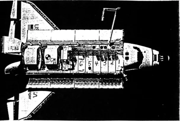
The Shuttle's payload compartment consists of 13 payload bays which are numbered from front to rear.
Figure 2-9, depicts the Shuttle's payload bays and their positions relative to the Shuttle's mass center.
Figure 2-9. Space Shuttle Payload Bays
The KITE spacecraft's size and weight allow it to be positioned in bays 2 through 13; however, there are other factors which must be considered.
The Remote Manipulator System (RMS) is a 50-foot mechanical arm which moves cargo around the payload bay. It is required to deploy and retrieve the KITE
spacecraft. Therefore, the KITE must be positioned to enable the RMS to grasp the KITE's Grapple Fixture. KITE's Grapple Fixture location, as indicated in figure
2-3, restricts its position and orientation in the
payload bay; however, calculations showed that upward orientation of the Grapple Fixture enables the RMS to remove and replace the KITE spacecraft from all payload bays.
A second consideration is KITE's payload priority.
The KITE is a secondary payload which means that its position in the payload compartment depends upon the placement of the primary cargo for that mission. It would be desirable for the KITE to ride in bay 10, near the Shuttle's mass center, because this would minimize tether torques imparted on the orbiter. This scenario is unlikely since the larger primary payloads are usually placed on or near the Shuttle's mass center. The most
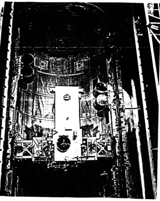
likely scenario is for KITE to ride in or close to bay 5 as a Spartan did during STS Mission 51-G. A view of the Spartan aboard Mission 51-G is depicted in figure 2-10.
CHAPTER 3
SPACECRAFT DEPLOYMENT
3.1 INTRODUCTION
Deployment of the Kinetic Isolation Tether
Experiment (KITE) spacecraft from the Space Shuttle is a relatively straight forward and stable operation. After an initial separation rate and distance between the
Shuttle and KITE spacecraft are established by Shuttle RCS jet firings, the gravity gradient forces will
continue tether deployment. Tether deployment friction, applied by the Small Expendable-tether Deployment System
(SEDS), controls the deployment rate according to a
proprietary control law. Due to the proprietary nature of the Small Expendable-tether Deployment System, this chapter discusses general deployment considerations and presents nominal deployment parameters rather than
focusing on a specific, hardware-dependent deployment profile. Nominal calculations based on a mathematically simplified deployment model are developed and compared with numerical simulation results from Energy Sciences Laboratory.
3.2 DEPLOYMENT CONSIDERATIONS
The Kinetic Isolation Tether Experiment has been tentatively budgeted 15 hours of mission time. The desire to conduct inertial and LVLH scanning at 5
different tether lengths demands that deployment time be minimized consistent with the following considerations.
The deployment should end with libration angles less than 10 degrees to enable the experiment to immediately proceed. If large libration angles develop as a result of deployment, they must be reduced below 10 degrees before the KITE spacecraft control system is activated.
Excitation of the tether longitudinal mode should be minimized. A fast deployment with strong braking toward
its completion will vigorously excite the longitudinal tether mode. Due to the physical properties of the tether, this mode is very lightly damped. Section 7.5 discusses the KITE spacecraft attitude errors induced by the combined effects of the mobile masses and excitation of the longitudinal mode. A measure of this excitation can be expressed as a percent variation of tether
tension. A rough goal for deployment may be to target a post deployment tension variation of no greater than 20%.
Final selection of this target must be based upon desired pointing accuracy for the KITE spacecraft, willingness to use Shuttle jet firings to damp this vibrational mode, and tension measurement capabilities.
3.3 A NOMINAL DEPLOYMENT SCENARIO
The KITE spacecraft will be removed from the payload bay by the Remote Manipulator System (RMS) and placed vertically upward or downward along the gravity gradient vector. For ease of discussion a downward deployment is
assumed. Positioning of the Small Expendable-tether Deployment System (SEDS) in the payload bay and RMS
operational restrictions limit the initial RMS deployment to approximately 30-40 feet. The Shuttle will then
thrust away from the KITE to overcome deployer friction and develop an opening rate and separation distance. After a separation distance of approximately 200 meters
has been established, deployment thrust is terminated and passive gravity gradient forces continue the deployment until the desired deployment length has been achieved. As the tether approaches the desired deployment length,
SEDS applies increased deployment friction to brake the
deployment and maintain the desired tether length.
3.4 A MATHEMATICALLY SIMPLIFIED DEPLOYMENT MODEL2 7
The objectives of this chapter are obtainable using a simplified mathematical deployment model. The
simplified model provides valuable insights into the
27 A. H. von Flotow and P. R. Williamson, "Deployment of
a Tethered Satellite Pair Into Low Earth Orbit for Plasma Diagnostics," Journal of Astronautical Sciences, Vol 34, No 1, January-March 1986, pp 65-90. Much of the analysis in this model is motivated from this source.
deployment problem prior to invoking more complex numerical simulations.
3.4.1 Modeling Assumptions
The following assumptions are used to develop
governing equations of motion for the simplified model: 1) The tether is assumed to remain straight because tether deflections from the nominal straight shape are damped and only weakly driven by Coriolis and aerodynamic forces.
2) Longitudinal and lateral deformations are assumed to be negligible.
3) The tether is assumed to be massless. Total tether mass (4-10 kg) is negligible compared to either the KITE (1053 kg) or the Shuttle (100,000 kg).
4) The Shuttle and KITE spacecraft are modeled as point masses. Attitude motion and inertia effects of the Shuttle and KITE spacecraft are neglected.
5) External forces arising from aerodynamic drag, solar pressure, electromagnetic interactions with the ambient magnetic field, variations in the gravitational field, and temperature variations are neglected.
3.4.2 Defining the LVLH Reference Frame
The Local-Vertical-Local-Horizontal (LVLH)
coordinate frame with its origin at the Shuttle-KITE
system center of mass is used. The following conventions are adopted:
Z-axis - positive direction up along the local vertical
X-axis - positive direction in the direction of flight and along the local horizontal
Y-axis - positive direction out of the orbital plane to complete the right handed system
3.4.3 Coordinate Frame Equations of Motion
If one assumes that the LVLH reference frame travels in a Keplerian orbit about a spherically symmetric Earth, then the relative motion of the KITE-Shuttle system
center of mass is described by the following equations.
S= ( w2 - GM / R3 ) X - 2 w - z + Fx / MT " = (- GM / R3) Y + F / MT (3-1) " = (2 GM / R3 + w2 ) Z + 2 w X + w X + Fz / MT where,
GM = Gravitational strength of the Earth
R = Distance from the system center-of-mass or coordinate frame origin to the Earth center w = Orbital rate of the LVLH origin
MT = Total system mass; sum of KITE, Shuttle, and tether masses
FxIFyIF = Components of external force, in addition to the gravitational force, acting on the system
3.4.4 Circular Orbit Approximation
Since typical Shuttle orbits have eccentricities less than 0.005, orbital rate (w) and radius (R) will change by less than one percent throughout the orbit. Therefore, we can adopt a circular reference orbit and simplify the equations of motion.
The circular reference orbit implies that orbital rate is constant.
= 0 and w2 = GM / R3 (3-2)
Then equations (3-1) become:
X = - 2 w Z + FX / MT
Y=-w 2 Y + Fy / MT (3-3)
S= 3 w2 Z + 2 w + Fz / MT
One can see from equations (3-3) that the circular orbit approximation decouples deployment computations from the system's position in the reference orbit.
3.4.5 Motion Equations About the System Mass Center
In this subsection equations are derived for system motion about its origin as the Shuttle backs away from the KITE spacecraft.
Assume that the Shuttle is traveling nose first and inverted with respect to the previously defined Local-Vertical-Local-Horizontal coordinate frame. Furthermore,
assume that the KITE spacecraft is deployed downward along the local vertical from the Shuttle via the RMS. Figure 3-1 depicts the proposed deployment orientation.
Z Up
X Forward
Ber
E
KITE
Figure 3-1. Nominal Orientation for KITE Deployment
The following parameters and approximations are defined to facilitate deployment analysis.
ep = In-plane pitch excursions from the local
vertical.
er = Out-of-plane roll excursions from the local vertical.
L = Separation distance, tether length,
between the Shuttle and KITE spacecraft. Icm = Instantaneous system roll/pitch inertia.
S = Tether deployment friction function. TLTepTr = Components of tether extraction thrust
parallel and normal to the tether. Bep = In-plane thrust misalignment angle. Ber = Out-of-plane thrust misalignment angle.
ms = Space Shuttle mass = 100,000 kg mk = KITE spacecraft mass = 1,053 kg
mt = total tether mass = 10 kg
MT = ms + mk + mt = 101,063 kg
The.proposed deployment orientation with the
previously defined conventions and parameters yield the following governing equations of motion.
L = L [ ( ep + w )2 cos2 er + r2 + 3 w2 cos2er cos2ep
- w2 ] - ( M
T S / m mk ) + TL / m
(3-4) 6p = ( Bp + w ) 2 8r tan e - 2 ( L / L ) ( 6p + w)
- 3 w2 cos ep sin
ep + ( Tep L mk / Icm MT cos2 er) '6r = - 2 ( L / L ) 8r - [ ( p + w )2 + 3 w2 Cp cos2 ]
cos er sin 8r + ( Tr L mk / Icm MT )
Equations (3-4) govern system motion as the Shuttle reaction control thrusters establish an opening rate and