Comparison of Zero-Valent Iron and Activated Carbon for Treating
Chlorinated Contaminants in Groundwater
by
Bina M. Indelicato
B.S. Environmental Engineering Massachusetts Institute of Technology, 1995Submitted to the Department of Civil and Environmental Engineering In Partial Fulfillment of the Requirements for the Degree of
MASTER OF ENGINEERING
IN CIVIL AND ENVIRONMENTAL ENGINEERING
at the
MASSACHUSETTS INSITITUTE OF TECHNOLOGY June 1998
©1998 Massachusetts Institute of Technology All rights Reserved
Signature of the Author
Department of Civil and Environmental Engineering May 8, 1998
Certified by
Dr. Albert B. Pincince Senior Lecturer of Civil and Environmental Engineering Camp Dresser and McKee Inc. Thesis Supervisor
Accepted by
"v Joseph M. Sussman
Chairman, Departmental Committee on Gradate Studies
JUN 02198
Comparison of Zero-Valent Iron and Activated Carbon for Treating Chlorinated Contaminants in Groundwater
by
Bina M. Indelicato
Submitted to the Department of Civil and Environmental Engineering on May 8, 1998 in Partial Fulfillment of the Requirements for the Degree of Master of Engineering in Civil and
Environmental Engineering
Abstract
The use of zero-valent iron to remediate chlorinated ground water is being explored at the Massachusetts Military Reservation (MMR). Zero-valent iron is inexpensive when compared to activated carbon, and is a destructive form of remediation. The technology involves a redox reaction between zero-valent iron and chlorinated solvents. The reaction results in non-toxic hydrocarbons, hydrogen gas, and hydroxide ions. This technology does not transfer contaminants from one medium to another, as in remediation schemes involving activated carbon or air stripping.
This thesis compares the use of activated carbon to the potential use of zero-valent iron at the MMR and for general sites. Specifically, the cost of implementing an aboveground system that utilizes zero-valent iron in place of activated carbon is compared. The cost of both systems is dictated by the flow rate and the contaminant concentrations.
Consequently, although the cost of iron ($450/ton) is much less than the cost of activated carbon ($2,000/ton), zero-valent iron is not a cost effective alternative at high flow rates such as 450 gallons per minute, which are the flow rates at the MMR. This is due to the enormous volume of iron required. Specifically, the amount of iron required is 55 times greater by weight than the amount of activated carbon required.
The second alternative explored in this thesis is the use of iron for treatment ahead of activated carbon. By using iron for pretreatment, the amount of activated carbon required would be decreased which may reduce the overall cost of the remediation scheme. However, this option is also not cost effective for the MMR.
For general sites, the cost comparison of carbon and iron gives similar results to that of the MMR site. Zero-valent iron is not a cost effective alternative to activated carbon for remediating chlorinated contaminants at concentrations ranging from 0.1 To 5 mg/1, regardless of the flow rate.
Thesis Supervisor: Dr. Albert B. Pincince
Title: Senior Lecturer of Civil and Environmental Engineering
_I --- II_-Y IP--lr-yl ~~ii ---Y-Y --~II~--*~ LIl- C-- ---- --s~i~ls~i_-~- 1I1I~
Acknowledgments
I would like to take this opportunity to thank the following people who have helped me complete this thesis:
my advisors, Dr. Al Pincince and Dr. Pete Shanahan,
Bruce Jacobs for introducing me to his friend Maple@, and helping me solve numerous differential equations, and
John Vogan of EnviroMetal Technologies, Inc. for supplying technical information on zero-valent iron.
Lastly, I'd like to thank my family and friends. I would like to especially thank my husband Tony, for his love and encouragement, and my parents for giving me everything I have ever needed to be successful.
Table of Contents
1. INTRODUCTION ... 11
1.1 PURPOSE ... ... 11
1.2 SC O PE L... ... 12
2. MASSACHUSETTSOLOGY ANDIL ITARY OPOGRESERVATION ... 12
2.1 L O CA TION ... ... 12
2 .2 H Y D RO LO G Y ... 13
2.3 HYDROGEOLOGY AND TOPOGRAPHY ... 14
2 .4 SITE H ISTO RY ... ... 14
2.5 STORM DRAINAGE DITCH NUMBER 5 PLUME... ... 15
2.6 EXTRACTION/TREATMENT/REINJECTION CAPTURE SYSTEM ... 17
2.7 C ONTAM INANTS ... ... ... ... ... 18
2. 7. 1 Tetrachloroethylene... 18
2.7.2 Trichloroethy lene... 19
2. 7.3 1,2-Dichloroethylene ... 20
2.7.4 Vinyl Chloride... 22
3. ZERO-VALENT IRON TECHNOLOGY ... 23
3.1 B ACKGROUND ... 23
3.2 C HEM ICAL R EACTION ... 25
3.3 THERM ODYNAM ICS ... 26
3.4 M ECHA N ISM ... 26
3.5 REACTION ORDER AND RATE ... 27
3.6 ZERO-VALENT IRON CONSUMPTION ... 28
4. USE OF ZERO-VALENT IRON IN REMEDIATION ... ... 29
4.1 OPERATING PARAMETERS ... 29
4. 1.1 Residence Time ... 29
4.1.2 Byp roducts ... ... 32
4.1.3 Precipitation ... 32
4.1.4 Temperature ... 33
4.1.5 Ratio of iron surface area to water volume ... 34
4.1.6 Gas Formation... ... 34
4.1.7 Inorganic Characteristics. ... ... 35...35
4 .2 PILO T T EST ... 36
4.2. 1 Zero-valent iron Treatability Study for Chemical Spill 10 ... 37
4.2.2 SITE Evaluation ofAboveground Systems... 38
4.3 MAINTENANCE REQUIREMENT ... ... 38
4.4 C O ST ... ... ... ... 39
4.5 ENHANCED IRON ... ... ... 40
4.5.1 N ickel-P lating ... 41
4.5.2 P alladium ... ... ... 42
5. ACTIVATED CARBON TECHNOLOGY ... 42
5.1 B ACKGROUN D ... ... 42
5.2 ACTIVATED CARBON SYSTEM AT SD-5 ... 43
6. COST COMPARISON OF ZERO-VALENT IRON AND ACTIVATED CARBON ... 44
06.1 COST OF IRON SYSTEM ... .. ... ... 44
6 1.1 Contam inant Concentrations ... 45
6 1.2 Reaction Rates ... 45
6 1.3 Residence Tim e Calculations... ... 46
6 1.4 Volum e of ron... ... 52
6 1.5 N um ber of Vessels... 52
6 1.6 Cost of ron System ... 52
6.2 COST OF CARBON SYSTEM ... 54
6.3 COST COM PARISON ... ... 57
6. 3.1 SD-5 System ... ... ... 57 6. 3.2 General Comparison ... ... 58 7. C O N C LU SIO N S ... 64 8. BIBLIO G RA PH Y ... 65 9. APPEN D IC ES ... 69 8
List of Figures
FIGURE 2-1: SD-5 PLUME ... ... 16
FIGURE 2-2: EXTRACTION-TREATMENT-REINJECTION (ETR) SYSTEM (MMRIRP, 1997B) ... 18
FIGURE 3-1: REACTIVE W ALL (U SEPA , 1996)...24
FIGURE 3-2: DEHALOGENATION REACTION... ... 26
FIGURE 4-1: DEGRADATION MODEL (ENVIROMETAL TECHNOLOGIES, 1998)... ... 30
FIGURE 6-1: DEGRADATION OF MEASURED CONCENTRATIONS USING ZERO-VALENT IRON...48
FIGURE 6-2: DEGRADATION OF MEASURED CONCENTRATIONS WITH NICKEL-PLATED IRON... 49
FIGURE 6-3: DEGRADATION OF DESIGN CONCENTRATIONS USING ZERO-VALENT IRON... 50
FIGURE 6-4: DEGRADATION OF DESIGN CONCENTRATIONS USING NICKEL-PLATED IRON ... 51
FIGURE 6-5: GRANULAR ACTIVATED ISOTHERM FOR CHLORINATED SOLVENTS (JACOBS, 1996B)... ... 55
FIGURE 6-6: ENHANCED IRON AND CARBON COST FOR CIS-DCE REMEDIATION ... ... 63
List of Tables
TABLE 2-1: PROPERTIES OF PCE ... ... ... ... ... 19TABLE 2-2: PROPERTIES OF TC E ... ... 20
TABLE 2-3: PROPERTIES OF CIS-1,2-DCE...21
TABLE 2-4: PROPERTIES OF VINYL CHLORIDE ... ... ... 22
T ABLE 4-1: H A LF L IV ES ... ... ... 29
TABLE 4-2: M OLECULAR FRACTIONS ... 32
TABLE 4-3: EFFECT OF SURFACE AREA TO VOLUME RATIO ON T1/2 VALUES FOR TCE DEGRADATION...34
TABLE 4-4: INORGANIC CHARACTERISTICS OF WATER IN AQUIFER AND PLUME AROUND REACTIVE IRON BARRIER..35
TABLE 4-5: COSTS ASSOCIATED WITH ABOVEGROUND SYSTEM...40
TABLE 4-6: ENHANCED IRON HALF-LIFE FOR COMMERCIAL NICKEL PLATED IRON... ... 41
TABLE 6-1: SD-5 CONTAMINANT CONCENTRATION AND REQUIRED CLEAN-UP LEVELS ... 45
TABLE 6-2: REACTION RATES ... ... ... 46
TABLE 6-3: RESIDENCE TIME ... .... ... ... ... ... 47
TABLE 6-4: SUMMARY OF ZERO-VALENT IRON COSTS... ... 54
TABLE 6-5: COST COMPARISON OF CARBON AND IRON (NPV) ... 57
TABLE 6-6: ADSORPTIVE CAPACITY OF CARBON AND RESIDENCE TIME OF IRON FOR GIVEN CONTAMINANT C ON CEN TRATION S ... 59
TABLE 6-7: IRON AND CARBON COST AS A FUNCTION OF FLOW RATE (GPM) ... 62
__--- ~I*P-T-r ---IY-^~^-~LIII--^ ~91 1_ --~sl~_1~l_-.14 1^IIIIILUL _-^I-III ~tC~I-_----~--~-YI
1.
Introduction
1.1
Purpose
Many of the remediation systems at the Massachusetts Military Reservation (MMR) use granular activated carbon for the removal of contaminants from ground water. Carbon is used primarily because it has given proven results. However, carbon is a costly treatment option at $2000/ton. In addition, after the carbon has adsorbed the contaminants, it requires further treatment to ultimately destroy the toxins. Given this information, the Massachusetts Military Reservation is exploring the possibilities of using cheaper alternatives to granular activated carbon.
This thesis assesses the feasibility of using zero-valent iron as a substitute for granular activated carbon. Zero-valent iron is cheaper ($450/ton) and destroys the contaminants instead of transferring them to another medium (Vogan, 1998).
The use of zero-valent iron in groundwater remediation has been increasing since it was recognized that zero-valent iron reacts with chlorinated hydrocarbons to produce non-toxic hydrocarbons. The reaction does not require external energy or additives, and is ideal for in-situ methods of groundwater remediation. This technology has been used to treat chlorinated ground water through the use of permeable walls. Permeable walls have been constructed with zero-valent iron as funnel and gate systems or as trenches built across the flow path of the contaminated ground water. However, permeable wall technology is only feasible for shallow plumes and becomes difficult to implement for plumes greater than 50 feet deep.
Since many of the plumes at MMR are deeper than 50 feet, zero-valent iron walls would not be easy to install. However, the use of zero-valent iron in aboveground treatment systems may be feasible. Zero-valent iron may prove to be an efficient substitute for activated carbon systems. It may also prove to be economical to use zero-valent iron as a pretreatment to activated carbon. Doing so may increase the life of activated carbon and decrease the frequency of replacing spent carbon.
..
__ ~I _I~ II~ _^^_II~___IIC___~I__~~~ --- ---~11_~1~
-1.2
Scope
This thesis explores the potential of utilizing zero-valent iron for treating plumes contaminated with chlorinated solvents at the MMR. Specifically, the cost of developing an aboveground system that utilizes zero-valent iron is explored. This cost is compared to the current use of granular activated carbon at the Storm Drain Number 5 (SD-5) Plume at the MMR. The cost and effectiveness of the remediation options are compared to determine if the use of zero-valent iron may be a better option. Specifically, the following options are compared:
* Activated carbon only
* Zero-valent iron as pretreatment to activated carbon * Zero-valent iron only
2. Massachusetts Military Reservation
2.1 Location
The Massachusetts Military Reservation (MMR) is located on the upper western part of Cape Cod, Massachusetts. It occupies 22,000 acres (35 square miles) within the towns of Bourne, Sandwich, Mashpee, and Falmouth in Barnstable County. The MMR consists of facilities operated by the U.S. Coast Guard, the Army National Guard, the U.S. Air Force, Air National Guard, U.S. Veterans Administration, and the Commonwealth of Massachusetts.
MMR comprises four principal functional areas (Jacobs, 1997b):
* Cantonment Area: This southern portion of the reservation is the most actively used section of the MMR. It occupies 5,000 acres and is the location of administration, operational, maintenance, housing, and support facilities for the base. The Otis Air Force Base facilities are located in the southeast portion of the Cantonment Area. * Range Maneuver and Impact Area: This northern part of the MMR consists of 14,000
acres and is used for training and maneuvers.
* Massachusetts National Cemetery: This area occupies the western edge of the MMR and contains the Veterans Administration Cemetery and support facilities.
Cape Cod Air Force Station (AFS): This 87-acre section is at the northern portion of the Range and Maneuver and Impact Area and is known as the Precision Acquisition Vehicle Entry -Phased Array Warning System.
A majority of the facilities at the MMR are located in the southern portion, while the northern portion consists of several firing ranges.
2.2 Hydrology
The continental climate of Cape Cod is strongly influenced by the Atlantic Ocean. Proximity to the ocean results in mitigated temperature extremes. February is the coldest month of the year, with daily temperatures ranging from an average minimum of 23 oF to an average maximum of 38 OF (ANG, 1993). July, the warmest month of the year, typically experiences average temperatures ranging from daily lows of 63 oF to daily highs of 78 OF (ANG, 1995). The oceanic influence results in warmer winters and cooler summers than those experienced in the inland areas of Massachusetts (ANG, 1995).
Cape Cod receives an average rainfall of 47.8 inches per year (ANG, 1995). The precipitation is distributed fairly evenly throughout the year, although a slightly higher portion of the precipitation occurs in the winter months (LeBlanc et al., 1986). The one-year/24-hour rainfall event for Cape Cod is 2.7 inches (Baker et al., 1997).
Due to the highly permeable sand and gravel deposits prevalent on Cape Cod, surface water runoff is less than 1% of the total precipitation (LeBlanc et al., 1986). Approximately 55% of the total precipitation is returned to the atmosphere via evaporation or transpiration by plants (LeBlanc et al., 1986). The remaining 45% infiltrates to recharge the ground water (LeBlanc et al., 1986).
Although ground water provides the main source of water for Cape Cod, approximately 4% of
Cape Cod is covered by surface-water bodies. These surface-water bodies, mainly intermittent streams or kettle holes, receive a net recharge of approximately 18 inches per year from direct precipitation (ANG, 1995).
_ ___~____~I X~~~__I1__1C__~I I_ _X__I ~_I_~~~C__ _LI^~_~1^ _ ^_L
The prevailing winds along Cape Cod are heavily influenced by the Atlantic Ocean and the Gulf Stream. From November through March, the prevailing winds arise from the northwest, whereas, from April through October, the prevailing winds originate from the southwest (ANG, 1995). Average wind speeds range from 9 miles per hour in the summer months to 12 miles per hour throughout the remainder of the year. Episodic tropical or ocean storms can result in exceedingly high wind velocities, ranging from 40 to 100 miles per hour (ANG, 1995).
2.3 Hydrogeology and Topography
The geology of western Cape Cod was shaped during the Wisconsin period, 85,000 to 7,000 years ago, of the Pleistocene epoch, with the advance and retreat of two glacial lobes that resulted in glaciofluvial sedimentation. To the north and west, the Buzzards Bay and Sandwich Moraines are composed mostly of glacial till. South is the Mashpee Pitted Plain, an outwash plain containing poorly sorted, fine- to coarse-grained outwash sands overlying finer-grained till and marine or lacustrine sediment. This lower layer of fine sediment has a hydraulic conductivity that is as much as five times less than that of the upper outwash layer, so that ground-water flow occurs mostly through the permeable upper layer. Seepage velocity within the sand and gravel outwash is estimated between 1 and 4.6 feet per day, with virtually no vertical flow. The entire plain is dotted with numerous kettle holes, bodies of water that resulted when large blocks of glacial ice, embedded in the sediment, melted. These ponds are maintained mostly by ground-water recharge and runoff.
The topography of the area can be characterized as a broad, flat, glacial outwash plain, dotted by kettle holes and other depressions, with marshy lowlands to the south, and flanked along the north and the west by recessional moraines and hummocky, irregular hills. Remnant river valleys cross the Mashpee Pitted Plain from north to south, while to the north and west the Buzzards Bay and Sandwich Moraines lend a higher degree of topographic relief.
2.4 Site History
Activities at the MMR began in 1911. Operational units at the MMR included the U.S. Air Force, U.S. Navy, U.S. Army, U.S. Marine Corps, U.S. National Guard, U.S. Army National Guard, and U.S. Coast Guard. Activities at the MMR have included troop development and
deployment, fire-fighting, ordnance development, testing and training, aircraft and vehicle operation and maintenance, and fuels transport and storage. Most activities are associated with either army training, maneuvers, or military aircraft operations, maintenance, support, and associated functions. From 1955 to 1970, a substantial number of surveillance and air defense aircraft operated out of the ANG portion of the reservation. Since that time, the intensity of operations has decreased substantially.
Past releases of hazardous materials at the MMR have resulted in ground-water contamination in a number of areas. Documented sources of contamination include former motor pools, landfills, fire-fighting training areas, and drainage structures such as dry wells. Several major plumes of ground-water contamination have been found to be migrating from these source areas and have been defined during extensive ground-water investigations.
2.5 Storm Drainage Ditch Number 5 Plume
The Storm Drainage Ditch No. 5 (SD-5) plume is located in the eastern portion of the Cantonment Area. The primary sources of this plume include the former Non-Destructive Inspection Laboratory dry well, the Corrosion Control Shop, and Hangers 3104 and 3192 (Jacobs, 1997a). The primary contaminants found at SD-5 and other plumes at MMR are trichloroethylene (TCE), tetrachloroethylene (PCE) and dichloroethylene (cis-DCE). The map of the SD-5 Plume is shown in Figure 2-1.
~-Source Area ETR Syst ' f 5' SD-5 Plume .~ ; :'::. I' i: . -r: -t: Legend SSD-5 Plume (Approximate)
- Base Boundary S n soF
Sieae in Feet Figure 2-1: SD-5 Plume Ashmet Pond Johns Pond Lj \t ?X: "i i. ., \
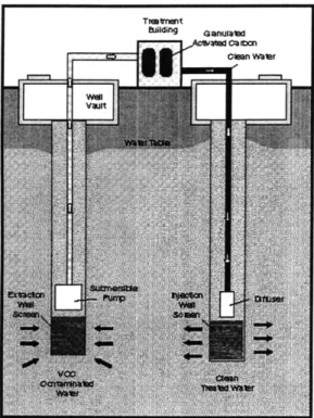
2.6 Extraction/Treatment/Reinjection Capture System
The SD-5 plume is currently being remediated with an Extraction-Treatment-Reinjection (ETR) system, a pump-and-treat system. The treatment method is activated carbon. In ETR technology, water is pumped from an aquifer, treated and returned to the aquifer. The design of this system is based on the nature and magnitude of the contaminants contained in a groundwater system; a characterization of the location, extent and behavior of the contaminated plume within the aquifer; aquifer characteristics; and an assessment of how the aquifer and plume will respond to pumping and reinjection (MMRIRP, 1997b).
At MMR, design criteria for the ETR system are based on a review of past operating procedures and past source-area and groundwater investigations, as well as field tests to estimate aquifer hydraulic characteristics. Monitoring wells are also used to characterize the nature and extent of the aquifer and contaminated waters. Aquifer pumping and reinjection tests are conducted to determine the aquifer's hydraulic characteristics and physical properties (MMRIRP, 1997b).
A series of extraction wells (an extraction fence) has been installed down gradient of the plume's leading edge or in an area of high contaminant concentration (MMRIRP, 1997b).
The extracted water is pumped through an underground piping system to a treatment system. The contaminated water is treated in a process system, such as granular activated carbon, to remove organic contaminants. If necessary, additional processes can be added to the system to treat inorganic elements, e.g., manganese and iron compounds. The chemistry of the water is adjusted as needed to increase the efficiency of the treatment. The treated water is pumped into another underground piping system to reinjection wells. The reinjection fence is located in an area where its impact on the ecology, the aquifer, and the extraction fence is determined to be minimal (MMRIRP, 1997b). Figure 2-2 illustrates how the ETR system operates.
Figure 2-2: Extraction-Treatment-Reinjection (ETR) system (MMRIRP, 1997b)
Currently, this method is used to treat SD-5 North plume. The treatment method is granular activated carbon.
2.7 Contaminants
Ten of the 25 most common contaminants found in ground water at hazardous waste sites are chlorinated solvents such as TCE. This is the result of the wide spread use of chlorinated solvents in dry cleaning fluid and metal degreasing solvents. These compounds pose problems due to their complex physical behavior in the subsurface and because of low concentrations allowed by drinking water standards (Gillham, 1996).
2.7.1 Tetrachloroethylene
Tetrachloroethylene (PCE) is a colorless DNAPL (dense nonaqueous phase liquid) with a chloroform or sweet, ethereal odor. The molecular structure of PCE is:
Cl Cl
C=C /
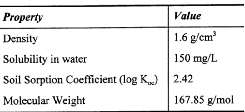
Properties of PCE are listed in Table 2-1.
Table 2-1: Properties of PCE
Property Value
Density 1.6 g/cm3
Solubility in water 150 mg/L
Soil Sorption Coefficient (log Koc) 2.42
Molecular Weight 167.85 g/mol
(Montgomery, 1996)
PCE has been used in:
* Dry cleaning fluids;
* Degreasing and drying metals and other solids;
* Solvents for waxes, greases, fats, oils, gums;
* Manufacturing printing inks and paint removers; * Preparation of fluorocarbons and trichloroacetic acid;
* Heat-transfer medium; and * Organic synthesis.
The Federal drinking water standard, or maximum contaminant level (MCL) is 5 ptg/l. Symptoms of exposure included headaches, drowsiness, dizziness, incoordination, and irritation of eyes, nose and throat. It is a narcotic at high concentrations. It is also a potential carcinogen (Montgomery, 1996).
2.7.2 Trichloroethylene
Trichloroethylene (TCE) is a DNAPL that is a clear, colorless, watery-liquid with a chloroform-like odor. The molecular structure of TCE is:
Cl Cl
/ \=C
Cl H
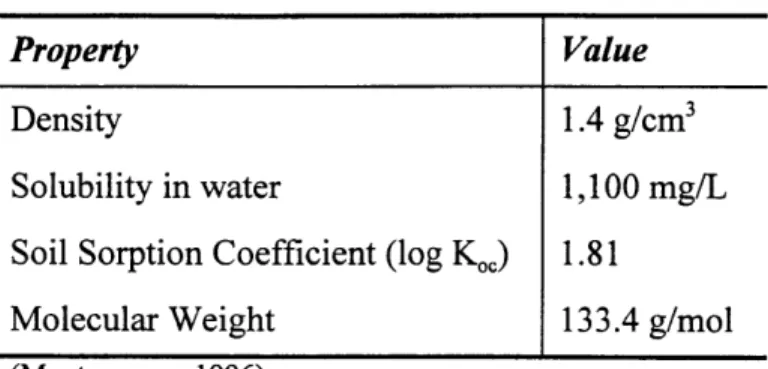
It is soluble in acetone, ethanol, chloroform and ether. Properties of TCE are listed in Table 2-2.
_ I_~~ ~LI~I~ _____1_1~__ ~II-eYIY-IIIYilY~i Ii ---I) -- --XIII^__ --L^IUIII-~LC~- I ~~ ~ _1~^1 -1--1^_ -1~111 111~~-~ 11_^1_1. ..-1--l1l1i~i- --^--. ~
Table 2-2: Properties of TCE
Property Value
Density 1.4 g/cm3
Solubility in water 1,100 mg/L
Soil Sorption Coefficient (log K0o) 1.81
Molecular Weight 133.4 g/mol
(Montgomery, 1996)
Symptoms of inhalation exposure include dizziness, headaches, fatigue and visual disturbance. Ingestion may cause nausea, vomiting, diarrhea and gastric disturbances. The Federal drinking water standard is 5 ptg/l. It is also a potential carcinogen (Montgomery, 1996).
TCE uses are varied and numerous. Some include * Dry cleaning fluids;
* Degreasing and drying metals and electronic parts; * Extraction solvent for oils waxes and fats;
* Solvents for cellulose esters and ethers; * Removing caffeine from coffee;
* Refrigerant and heat exchange liquid; * Anesthetic;
* Medicine; and * Organic synthesis.
2.7.3 1,2-Dichloroethylene
1,2-Dichloroethylene (1,2-DCE) is a colorless liquid with an ethereal, slightly acrid odor. It has two forms with different molecular structures:
Cl Cl
"C=C/
H H
Cl H
"c=c
/
H C1
trans- 1,2-DCE
Properties of cis-1,2-DCE are listed in Table 2-3.
Table 2-3: Properties of cis-1,2-DCE
Property Value
Density 1.27 g/cm'
Solubility in water 3500 mg/L
Molecular Weight 96.94 g/mol
(Prager, 1996)
1,2-DCE is soluble in most organic solvents such as alcohol, ether, acetone, benzene and
chloroform. 1,2-DCE can be corrosive towards some forms of plastics, rubber and coatings. Common uses of 1,2-DCE include:
* Solvents for fats, phenol, and camphor;
* Retarding fermentation;
* Solvent for natural rubber;
* Coolant in refrigeration plants; * Low temperature solvent;
* Dye extraction; * Perfumes;
* Organic synthesis; and
* Extracting agent for heat sensitive substances such as perfume oils and caffeine in coffee.
Symptoms of inhalation include dizziness, nausea, vomiting, or difficult breathing (Prager, 1996). The Federal drinking water standard for cis-1,2-DCE is 70 tg/l.
~~114_ _____~1_1~_^ _ __I_ _I___IY~__UII____ - -L1- C__---.._.__. .^-_II~~~ ~-- - IY-UL ~1-~1111_1 ~11- li^l _^_L-~tll~---r. .IIC--~ ---.--- L-~--I____._.
2.7.4 Vinyl Chloride
Vinyl chloride (VC) is a colorless, liquefied compressed gas with a faint sweetish odor. The molecular structure of VC is:
H H
"C=C/
H C1
Properties of vinyl chloride are listed in Table 2-4.
Table 2-4: Properties of Vinyl Chloride
Property Value
Density 0.91 g/cm3
Solubility in water 1,100 mg/L
Soil Sorption Coefficient (log Koc) 0.39
Molecular Weight 62.5 g/mol
(Montgomery, 1996)
Since vinyl chloride has a density less than water, it is classified as a LNAPL (light nonaqueous phase liquid). It is soluble in ethanol, carbon tetrachloride and ether. The Federal drinking water standard is 2 pg/l. Its uses include:
* Manufacturing of polyvinyl chloride and copolymers; * Adhesives for plastics;
* Refrigerants;
* Extraction solvent; and * Organic synthesis.
VC is a potential carcinogen. At high concentrations, vinyl chloride is a narcotic (Montgomery, 1996).
3. Zero-valent Iron Technology
3.1 Background
The use of zero-valent iron in groundwater remediation was developed at the University of Waterloo (UW) in Ontario, Canada. It was later commercialized in 1992 through EnviroMetal Technologies, Inc. (ETI) of Waterloo, Ontario (Vogan, 1995).
The metal-enhanced dechlorination technology involves oxidation of zero-valent iron and reductive dehalogenation of volatile organic compounds (VOCs). The process degrades dissolved halogenated organic chemicals from ground water including common chlorinated compounds such as:
* Tetrachloroethene (PCE) * Trichloroethene (TCE)
* Dichloroethene Isomers (DCEs)
* Vinyl Chloride (VC)
* Trichloroethane (TCA)
* Tetrachloromethane (CT) * Ethylene Dibromide (EDB)
The main advantage of using zero-valent iron for remediation is the destructive nature of the process. It does not result in the transfer of chemicals from one medium to another, but rather destroys the contaminants in a redox reaction. In addition, the end products include hydrogen gas, dechlorinated hydrocarbons such as ethene, and chloride in solution, which are all nontoxic.
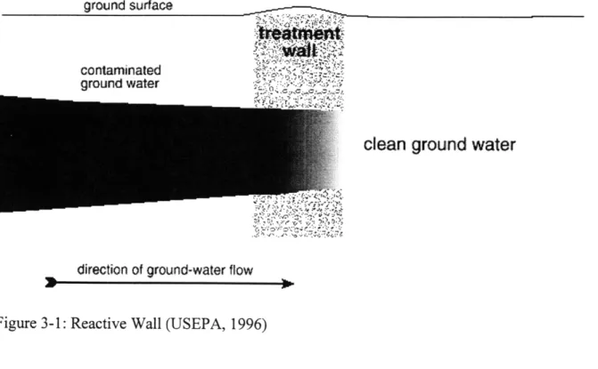
The technology has been implemented at several locations with the use of permeable walls as shown in Figure 3-1.
ground surface
contaminated ground water
clean ground water
direction of ground-water flow
Figure 3-1: Reactive Wall (USEPA, 1996)
There are basically two designs used in full-scale implementation of reactive barriers: (1) funnel and gate; and, (2) a continuous trench. The funnel-and-gate system is constructed using interlocking sheet pilings or a slurry wall. The pilings or wall is employed to enclose the plume and direct it to the gate containing the permeable zone of zero-valent iron. The permeable zone is designed to have a much higher permeability than the soil surrounding the system to prevent ground water from flowing around the wall instead of through it (USEPA, 1997b).
The continuous trench design involves excavating and backfilling a trench with zero-valent iron. It also is designed to intercept the plume (USEPA, 1997b).
The continuous trench and funnel-and-gate technologies are ideal for in-situ treatment because the system does not require energy or additives for the dehalogenation to take place. However, permeable barriers are not suitable for every location, particularly areas with deep plumes.
Zero-valent iron can also be used in aboveground treatment systems as part of a pump-and-treat remediation scheme. It can be used in place of activated carbon or air stripping. Aboveground systems are not as maintenance free as in-situ systems of zero-valent iron since injection and extraction wells are required for the aboveground system.
The primary disadvantage of using zero-valent iron technology for groundwater remediation is that the precise pathway of the reaction between zero-valent iron and chlorinated hydrocarbons is
not known. This makes it difficult to develop an optimal design for a remediation system.
3.2 Chemical Reaction
The reaction between zero-valent iron and chlorinated compounds is a reduction-oxidation (redox) which causes the substitution of halogen atoms by hydrogen atoms (USEPA, 1997a). This causes iron to rust and the contaminant to become dechlorinated. Zero-valent iron has been shown to destroy chlorinated compounds and immobilize several hazardous metals such as chromium, selenium, technetium and uranium (Kaplan, 1997). Although the products and reactants of the redox reaction have been determined, the details of the reaction between iron and chlorinated compounds are not fully understood.
It is believed that dechlorination occurs at the surface of the iron fillings. In the dechlorination reaction, iron atoms donate electrons, breaking the bond between chlorine atoms and the carbon atom. Most of the chlorine is released as harmless chloride ion or combines with ferrous iron to precipitate as green rust. Byproducts include partially dechlorinated compounds, such as vinyl chloride, and completely dechlorinated compounds such as ethene and ethane.
The overall reaction is a redox reaction that takes place in the presence of water, zero-valent iron (FeO) and chlorinated hydrocarbon (RC1).
2Feo -* 2Fe2 + + 4e- (1) 3H20 + - 3H + 30H- (2) 2H+ + 2e- -+ H2(g) (3) RCl + H' + 2e- - RH + Cl- (4) 2Feo + 3H20 + RCl -- 2Fe2+ + 30H- + H2(g) + RH + Cl- (5)
Reaction (1) is the corrosion of iron and reaction (2) is the ionization of water. The electrons
resulting from the corrosion of iron react with the hydrogen ions and the halogenated
hydrocarbon (RC1) to form Fe2", hydroxyl ions (OH-), hydrogen gas (H2(g)), non-halogenated
hydrocarbon (RH) and chloride ions (CI-) (USEPA, 1997a).
3.3 Thermodynamics
The dehalogenation of chlorinated compounds is a thermodynamically favorable reaction. The carbon in halogenated compounds is in an oxidized state due to the chlorine atom, and is likely to degrade under reducing conditions produced by the reduced metal (Feo) (Orth, 1993). In addition, the higher chlorinated compounds are the most highly oxidized and have the highest degradation rates in reducing environments (Gillham, 1996). Therefore, compounds such as PCE would dehalogenate faster than DCE. This is generally the case; however, half-lives tend to vary under different conditions (USEPA, 1997a).
3.4 Mechanism
Reactions involving multi-chlorinated hydrocarbons and zero-valent iron are not fully understood. There are two general mechanisms by which reductive dehalogenation can take place: hydrogenolysis (replacement of a halogen by a hydrogen) and reductive p-elimination (two halides are released). Both mechanisms involve the net transfer of two electrons from the chlorinated compound to the electron acceptor (zero-valent iron). Research has indicated that reductive P-elimination reactions with chlorinated ethenes, such as PCE and TCE, are energetically comparable to hydrogenolysis (Roberts et al., 1996).
During the hydrogenolysis reaction, sequential dechlorination of these compounds occurs. The multi-chlorinated compound is converted to less chlorinated compounds and then eventually to hydrocarbons such as ethenes and ethanes. For example, PCE would be converted to TCE, then to DCE, and then to vinyl chloride before being completely dechlorinated, as shown in Figure 3-2.
H CI H CI H Cl H CI
PCE -4 TCE - DCE "-4 VC - =4 ethene
The dehalogenation reaction is believed to be either a continuous (precipitous) reaction (Gillham, 1996), or a sequential reaction, or a combination of both. For example, if the reaction is precipitous, the TCE would be attached to the iron surface until enough electrons have been transferred to complete the dechlorination. This may be due to the hydrophobic nature of TCE or to the covalent bond formed after the first electron transfer (Orth and Gillham, 1996). If the reaction is sequential, on the other hand, each chlorine atom would be removed in a separate reaction (USEPA, 1997a).
In laboratory tests conducted on the degradation of chlorinated compounds, small amounts of chlorinated intermediates were detected. Therefore, the degradation reaction may not be completely sequential since this reaction would generate a greater amount of intermediates (Orth and Gillham, 1996). It is proposed that low concentrations of intermediate degradation products are the result of the continuous reaction in which incidental releases occur from the iron surface during the degradation process (Gillham, 1996).
Although the actual mechanism of the dechlorination does not affect the overall results of the dechlorination, the mechanism will need to be fully understood in order to design an optimal treatment system.
3.5 Reaction Order and Rate
The redox reaction is believed to be pseudo-first order. Since the reaction does occur on the surface of the iron, the reaction is dependent on the availability of surface area. Therefore, as the system becomes saturated, the reaction may no longer be pseudo-first order. However, according to Orth and Gillham (1996), the concentrations of TCE found in ground water are not high enough to cause a saturation of iron surfaces and the use of pseudo-first order models is appropriate. For TCE, the rate constant is relatively insensitive to the initial concentration over the range of 1.3-61 mg/l.
Reaction rates are often reported by way of half-lives, which is the time required to decrease the initial concentration by half. Zero-valent iron has been shown to have typical half-lives of 1.1 to 4.6 hours for TCE and 2.1 to 10.8 hours for PCE, when normalized to 1 m2 of iron surface per
milliliter of solution. (O'Hannesin and Gillham, 1997). (Since the reaction is dependent on the
.. _1-~- ^*~-^~llli---*-1- 11- -("- ---Llsl~-- -~--rrcu-- II -i
available surface area of zero-valent iron, normalizing half-lives to 1 m2/ml provides a method for comparison.) This is 5 to 15 orders of magnitude greater than natural abiotic rates.
In a long term performance test conducted for an in-situ iron wall at the Canadian Forces Base in Borden, Ontario, reaction rates determined in the laboratory matched the observed field data in order of magnitude. Therefore, lab tests can be useful to determine parameters for design of a treatment system. In addition, the kinetics of the degradation was reasonably consistent with the first-order decay model (O'Hannesin and Gillham, 1997).
It is important to note that the half-life determined in the laboratory may be less than the half-life observed in the field due to differences in conditions such as temperature and mineral content of the water. High temperatures yield faster reaction times and therefore lower half-lives. In addition, precipitate may decrease iron surface areas and inhibit reactions. Therefore, it may be appropriate to increase the laboratory half-lives by as much as two orders of magnitude when determining field half-lives (Hubble and Gillham, 1997b).
It is important to note that the reaction rate of higher chlorinated compounds is greater than that of lower chlorinated compounds. This is evident in looking at the reaction rates for PCE, TCE, DCE and VC. PCE and TCE tend to degrade at reasonably similar rates. However, the rate is
lower for DCE and VC (Gillham, 1996).
3.6 Zero-valent Iron Consumption
The iron granules are dissolved by the dehalogenation process, but the metal disappears so slowly that the media will be able to treat large quantities of chlorinated solvents (USEPA, 1996). For example, based on the electron requirement for the redox reaction, 1 kg of iron could completely dechlorinate the carbon tetrachloride in 130,000 gallons of water at an initial concentration of 1 mg/1 (Gillham and O'Hannesin, 1994). However, since the corrosion of iron occurs quicker through the dissociation of water than the dechlorination reaction, the rate of iron consumption would be greater in the presence of water than with just iron and halogenated compounds. But it is still reasonable to expect that zero-valent iron in walls and aboveground systems will last for years (Gillham and O'Hannesin, 1994).
4. Use of Zero-valent Iron in Remediation
In order to determine the feasibility of using zero-valent iron for remediating ground water at MMR, operating parameters, previous pilot tests, maintenance requirements and costs should be evaluated.
4.1
Operating Parameters
In order to design an aboveground system using zero-valent iron, several parameters must be considered.
4.1.1 Residence Time
The key parameter in designing a remediation system that utilizes zero-valent iron is the residence time. Residence time is defined as the time required to decrease the concentration of contaminants to the desired levels. To calculate the residence time for given concentrations, the reaction rate of the compounds must be determined. This is often done through column tests in treatability studies.
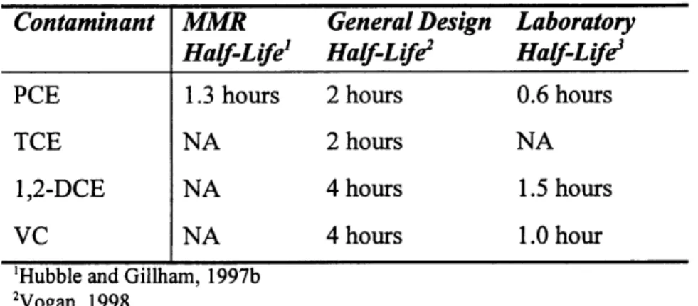
Reaction rates are used to calculate half-lives. Half-lives for selected chlorinated compounds are given in Table 4-5.
Table 4-1: Half Lives
Contaminant MMR General Design Laboratory
Half-Life' Half-Life2 Half-Life
PCE 1.3 hours 2 hours 0.6 hours
TCE NA 2 hours NA
1,2-DCE NA 4 hours 1.5 hours
VC NA 4 hours 1.0 hour
'Hubble and Gillham, 1997b 'Vogan, 1998
3 Focht et al., 1996
MMR half-life is the value obtained from a treatability study discussed in later sections. The
general design half-lives are estimated values used when assessing the feasibility of using zero-valent iron prior to conducting a treatability study. This half-life is for 100% iron at 5:1 ratio for
^I~--- --- ~-, ---" - '-- II-~ I-*-r---rr---~ I---- ~- l ---rr~lr-- I--a*---r*1--~l
surface area:volume for ground water (Vogan, 1998). The laboratory half-lives are values obtained in laboratory column tests.
The half-lives used for assessing the feasibility of using zero-valent iron at MMR are the general design values for TCE, cis-DCE and VC, and the MMR value for PCE.
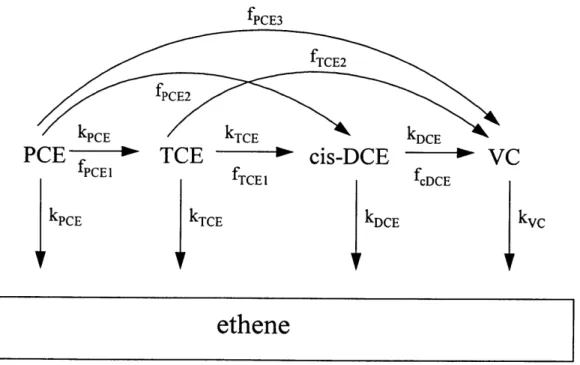
Once the half-life is determined, the residence time can be determined using a degradation model developed by EnviroMetal Technologies, Inc. The model is based on the reaction sequences in Figure 4-1.
fPCE3
V kPCE kTCE
PCE
TCE
-
cis-DCE
fPCE1 fTCE
kPcE kTcE IkDcE
kDCE
fcDCE
VC
I
kvcethene
The equations which correspond to the degradation model are given in equations (6) through (9).
dPCE k PCE (6)
dt PCE
dTCEdTCE = fPcE kPCE PCE - kTCE TCE (7)
dt
dcDCE
dDCE
= fPCE2kPCEPCE + fTCElkTCETCE - kcDCEDCE (8)dt
dVCdV fPCE3kPCE PCE + fTCE
2kTCE TCE + fcDCE kcDCE cDCE - kvcVC (9) dt
This Degradation Model accounts for the byproducts that are formed in the degradation of PCE, TCE and cis-DCE. For example, although a majority of PCE is thought to degrade to ethene, it is believed that 25% (fPcEl) of PCE is converted to TCE instead. This model is able to calculate the
concentration of PCE, TCE, cis-DCE and VC at any given time given these multiple pathways.
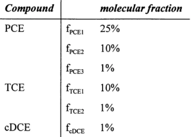
Since the exact mechanism for the degradation process is not known, this degradation model was developed as a method for determining required residence times for remediation systems. O'Hannesin and Gillham (1997) determined the molecular fractions (f) by fitting observed data to an analytical sequential degradation model. The molecular fractions used in implementing the model for assessing the feasibility of using zero-valent iron at MMR are given in Table 4-2. The
reaction rates used were calculated from half-lives in Table 4-5.
_ ^--- --- ^---~c-- L- r~- ~. ~.- .I-...-ll--..lllp--*Isr*rryr*~ CLLi n-~- I..~ ---XXI~X-IPi^.-~qplll^- CI. lk~
Table 4-2: Molecular Fractions Compound molecularfraction PCE fPCE1 25% fPcE2 10% fPCE3 1% TCE fTcEl 10% fTCE2 1% cDCE fcDCE 1%
(EnviroMetal Technologies, Inc., 1998)
4.1.2 Byproducts
Byproducts of the reaction between zero-valent iron and halogenated compounds include hydrogen gas, hydrocarbons (such as ethane and ethene), chloride in solution, and some halogenated intermediates. Test results show that approximately 10% of initial TCE and PCE appear as cis-DCE, while 1% of PCE, TCE and DCE appear as vinyl chloride as shown in Figure 4-1 (Vogan et al., 1995). This may be a problem because the drinking water standard for vinyl
chloride is 2 pg/l, and 70 jtg/l for cis-DCE (Orth and Gillham, 1996). Therefore, additional time may be required to treat these byproducts. However, if the original concentrations of TCE, PCE and DCE are fairly low, the amount of chlorinated byproducts may be lower than MCLs, thus eliminating the need for additional residence time (Vogan, 1998).
4.1.3 Precipitation
Precipitation caused by the reaction between inorganic elements in the ground water and hydroxide ions from the dehalogenation reaction can inhibit the remediation process. Precipitate can cause clogging and coating that may inhibit the performance of zero-valent iron in dehalogenating chlorinated compounds. Precipitate may also affect the hydraulics of the vessel by impairing the flow through the zero-valent iron media and thereby lead to channeling. This would result in the contaminants bypassing portions of the zero-valent iron, causing some compounds to reach deeper into the vessel before becoming dechlorinated. In such cases, the
compound may not experience appropriate residence times and complete dechlorination may not be achieved (USEPA, 1997a).
Precipitation can occur under various conditions. If no oxygen is present and pH is high, ferrous hydroxide will precipitate.
Fe2 + 20H- -+ Fe(OH)2(s) (ferrous hydroxide) (10)
In oxygenated water at high pH, Fe2+ is converted into ferric iron (Fe3 ) which could precipitate as ferric hydroxide.
Fe'3 + 30H- - Fe(OH)3 (s) (ferric hydroxide) (11)
Increases in pH can also cause OH- to react with bicarbonate ions (HCO3") in ground water and cause calcium carbonate (CaCO3) to precipitate.
HC03- + OH" -- H20 + CO3 2
- (12)
Ca2+ + CO32-- CaCO3 (s) (13)
In addition,,at low dissolved oxygen concentration, carbonate (C0 32) may react with Fe2+ to form
ferrous carbonate (siderite) [FeCO3] (USEPA, 1997a).
Fe2+ + CO32- - FeCO3(s) (14)
In order to alleviate problems caused by precipitates, periodic flushing of the iron may be required every few years if the ground water has a high mineral content. This is one area that will require further investigation to optimize zero-valent remediation system (Orth and Gillham,
1996).
4.1.4 Temperature
As in many reactions, decrease in temperature decreases the reaction rate between zero-valent iron and halogenated compounds. In a pilot test of an aboveground vessel with zero-valent iron, a
reduction in PCE removal efficiency generally coincided with a decrease in ambient temperature and water temperature (USEPA, 1997a). Therefore, it is important to account for any potential temperature changes in the water being treated when designing a zero-valent system.
4.1.5 Ratio of iron surface area to water volume
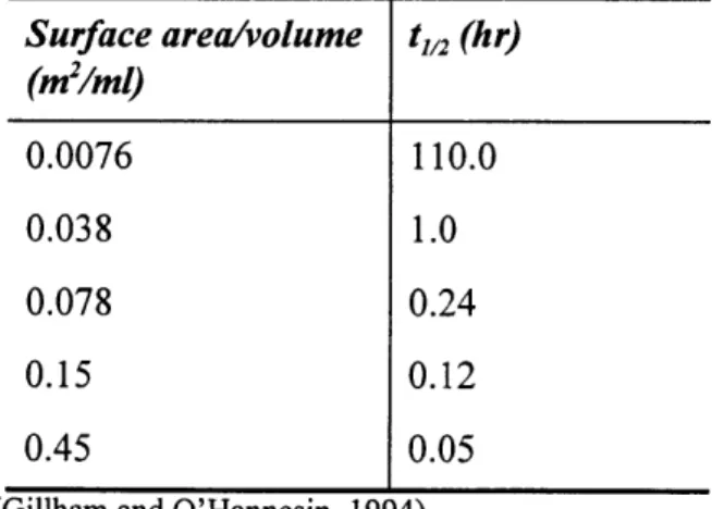
Laboratory experiments have shown that reaction rates of the dehalogenation are related to the ratio of iron surface area and water volume. A higher ratio has shown to give faster dehalogenation rates. In column experiments, the half-lives in iron columns with 100% iron were consistently lower than for samples with 50% iron and 50% sand (Vogan et al., 1995). Therefore, any reduction in available surface area may increase the time required to obtain dehalogenation (USEPA, 1997a). The results of tests to examine the effect of the surface area to solution volume ratio on half-lives (tl/2) of TCE are given in Table 4-3 (Gillham and O'Hannesin, 1994).
Table 4-3: Effect of Surface Area to Volume Ratio on t,,2 Values for TCE Degradation Surface area/volume tl/2 (hr) (m2/ml) 0.0076 110.0 0.038 1.0 0.078 0.24 0.15 0.12 0.45 0.05
(Gillham and O'Hannesin, 1994)
At low values of surface area to volume ratio, the half-life is disproportionately high. Gillham believes that this is due to the possibility that with smaller amounts of iron, a longer time would be required for the solute to contact an iron surface. After the surface area to volume ratio has reached 0.078 m2
/ml the rate of degradation of TCE would be limited by reaction rates and would no longer would depend on mass transfer rates. A second hypothesis is that in the presence of small amount of iron, a longer time period is required for the solution chemistry to develop (Gillham and O'Hannesin, 1994). In any case, it is apparent from Table 4-3 that the dehalogenation proceeds faster as more surface area of zero-valent iron becomes available.
4.1.6 Gas Formation
Since the dehalogenation of chlorinated VOCs by zero-valent iron produces hydrogen gas, the aboveground system must be designed to allow the gas to escape and not inhibit the flow through the media. If this gas is not properly ventilated, the build up of gas may decrease porosity and
therefore increase the flow rate through the media and ultimately decrease the contaminant removal rate.
4.1.7 Inorganic Characteristics
The inorganic characteristics of ground water being treated by zero-valent iron may change dramatically due to the redox reaction occurring between iron and chlorinated compounds. Since one of the main products of the redox reaction is hydroxide ions (OH-), the pH of the ground water changes as the reaction proceeds. Consequently, concentration of dissolved metals such as calcium, magnesium and barium decrease as pH increases. Table 4-8 gives the dissolved metals' concentrations and other inorganic properties of a zero-valent iron system.
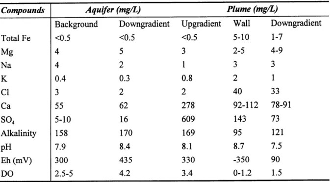
Table 4-4: Inorganic Characteristics of Water in Aquifer and Plume around Reactive Iron Barrier
Compounds Aquifer (mg/L) Plume (mg/L)
Background Downgradient Upgradient Wall Downgradient
Total Fe <0.5 <0.5 <0.5 5-10 1-7 Mg 4 5 3 2-5 4-9 Na 4 2 1 3 3 K 0.4 0.3 0.8 2 1 Cl 3 2 2 40 33 Ca 55 62 278 92-112 78-91 SO04 5-10 16 609 143 73 Alkalinity 158 170 169 95 121 pH 7.9 8.4 8.1 8.7 7.5 Eh (mV) 300 435 330 -350 90 DO 2.5-5 4.2 3.4 0-1.2 1.5
(O'Hannesin and Gillham, 1997)
Background aquifer values are from areas outside the influence of the contaminant plume and reactive iron wall. Downgradient values are from downgradient of the wall but unaffected by the plume. The values listed under Plume reflect conditions in the plume upgradient of the wall, in the wall and downgradient of the wall (O'Hannesin and Gillham, 1997).
The manganese (Mg), sodium (Na) and potassium (K) concentrations were not affected greatly. pH did increase within the wall, but resumed to normal downgradient. The increase in Cl is the result of the dechlorination of the contaminants in the plume.
Calcium (Ca) and sulfate (SO4) decreased as the plume passed through the wall, indicating that
calcium carbonate and siderite were precipitating within the wall.
Iron concentration did increase in the wall, but began to decrease downgradient again due to iron precipitating out as iron oxyhydroxide and as siderite (O'Hannesin and Gillham, 1997).
The reducing environment caused by the redox reaction causes a decrease in specific conductance (Eh) and dissolved oxygen concentration (DO). Decrease in Eh is probably caused by the removal of ions during treatment. Removal of ions may occur through formation of metal hydroxides or metal-carbonate precipitate. Formation of these precipitates may remove metal
cations, hydroxyl ions and carbonate ions from ground water (USEPA, 1997a).
Biological studies of this wall after year one and year two of operation concluded that there were very low levels of biological activity, indicating low possibility of biofouling (O'Hannesin and Gillham, 1997).
4.2 Pilot Test
In order to assess the feasibility of using zero-valent iron for groundwater remediation, a pilot test should be conducted. This is done to determine if the iron will effectively remove the contaminants and to determine the reaction rates of the removal. Unfortunately, a pilot test has not been conducted for the use of zero-valent iron for the SD-5 plume. However, there has been a treatability study conducted for the use of a zero-valent permeable wall at Chemical Spill 10 at MMR. This study will be used to assess the feasibility of using zero-valent iron at SD-5 since groundwater conditions are similar for the two plumes.
In addition to the treatability study from CS-10, a Superfund Innovative Technology Evaluation (SITE) Program Report is used in this thesis to assess feasibility. This SITE report is an evaluation of an aboveground reactor used for remediating ground water at a site in Wayne, New Jersey.
4.2.1 Zero-valent iron Treatability Study for Chemical Spill 10
Zero-valent iron technology has been assessed previously for use at the MMR. The MMR is installing a zero-valent iron wall to remediate the Chemical Spill Number 10 (CS-10) Plume. The primary contaminants of CS-10 plume are PCE, TCE and cis-DCE. Although it was determined that the depth of this plume is too great to use conventional excavation and backfilling techniques, advanced technologies involving hydraulic fracturing have been selected for the emplacement method (Hubble and Gillham, 1997a).
In order to properly assess the feasibility of using zero-valent iron at CS-10, a treatability study was conducted by the Institute for Groundwater Research at the University of Waterloo, Ontario, Canada. The study involved collecting groundwater samples from CS-10. The samples were passed through test columns containing granular iron. The objective of these tests was to determine if the organic compounds found in the CS-10 plume would degrade if passed through zero-valent iron and to measure degradation rates. Concentrations of manganese and other elements were also measured to assess the effects of the zero-valent iron on the inorganic elements of the ground water (Hubble and Gillham, 1997b).
Based on the column tests, the half-life of PCE is 39 minutes. To determine the design half-life, a factor of two is used to account for lower temperatures in the field. Therefore the design half-life for PCE is 1.3 hours (Hubble and Gillham, 1997b).
Inorganic results of the column tests showed that Eh of the ground water decreased from +320mV to about -250mV as it traveled through the zero-valent iron column. The pH increased to between 9 and 10 (Hubble and Gillham, 1997b).
There was little change in the aqueous potassium (K), sodium (Na), zinc (Zn), and chloride (Cl) concentrations as the ground water passed through the zero-valent iron column. The concentrations of calcium (Ca), sulfate (SO4) and alkalinity increased in the effluent. Aqueous
magnesium (Mg), silica (Si) and nitrate (NO3) decreased. The aqueous iron (Fe) did increase
after 68 pore volumes passed though the column (Hubble and Gillham, 1997b).
4.2.2 SITE Evaluation of Aboveground Systems
An evaluation of an aboveground vessel for remediation of contaminated ground water was conducted for a SITE evaluation in Wayne, New Jersey for three months during 1994. A reactive, zero-valent, granular iron medium was used in a vessel. The vessel consisted of an air eliminator, 5-micron water filter to remove suspended solids, and a flow meter. After passing through these, the water flows through the zero-valent iron medium and through a collector line at the bottom of the vessel. The vessel was designed to maintain about one foot of ponded water above the surface of the iron to prevent dewatering of the reactive media. A gas vent at the top of the vessel allows for built up gas from the reaction to escape. The vessel includes the zero-valent iron, pea gravel or well sand, and the necessary plumbing and piping (USEPA, 1997a).
For the SITE evaluation, the flow rate through the vessel was maintained at 0.5 gallons per minute. The removal efficiency of TCE and PCE exceeded 99.98%. Vinyl chloride and cDCE were detected after 6 weeks of testing and occasionally exceeded NJDEP regulatory limits (Chen, 1995).
The estimated porosity loss (after 80 pore volumes) from calcium carbonate, iron carbonate, and iron hydroxide precipitation was approximately 2.2% for the first foot, 1.5% for the next foot and 1.2% for the remainder of the canister. After 200 pore volumes, the porosity loss was 4.5% for the first foot, 5.4% for the second foot and 2.3% for the remainder of the canister. To alleviate these problems of porosity losses in the aboveground systems, EnviroMetal Technologies recommends that a highly permeable upper layer of the reactive media be created using a mix of pea gravel and iron to minimize the effects of precipitate (USEPA, 1997a).
The use of this technology depends on site-specific factors. The volume of contaminated water requiring treatment may affect the applicability of an aboveground treatment system. Groundwater chemistry, contaminant types and concentrations may affect how the technology is applied (USEPA, 1997a).
4.3 Maintenance Requirement
Unlike the in-situ reactive wall application, the aboveground system will require regular maintenance. Suspended solids in the influent ground water may cause some clogging on the
zero-valent iron. Also, precipitation may also cause clogging and coating. Therefore, it may be necessary to periodically replace the top section of the zero-valent iron bed or break it up. There may also be problems with algae and bacterial growth in the ponded water above the zero-valent iron bed. This may eventually restrict flow throughout the system. Therefore, it may be necessary to limit light into the system or use chemical algaecides. (USEPA, 1997a)
4.4 Cost
Zero-valent iron costs are approximately $400/ton with about $30-$40/ton for shipping. Currently, it is believed that iron in remediation systems will need to be replaced or mixed every 5 to 10 years. However, since there is no long-term data available, these numbers are educated guesses and not proven facts. (Vogan, 1998)
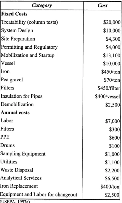
Other costs associated with an aboveground iron vessel are listed in Table 6-9. The costs listed are specifically those associated with the aboveground vessel at the SITE location in New Jersey. The total fixed and variable costs of any aboveground zero-valent iron system would be dependent on the number of vessels and the amount of iron required. Therefore, Table 4-9 is presented only to give an indication of costs of other resources required to construct and operate an aboveground system.
Table 4-5: Costs Associated with Aboveground System
Fixed Costs
Treatability (column tests) System Design
Site Preparation
Permitting and Regulatory Mobilization and Startup Vessel
Iron Pea gravel Filters
Insulation for Pipes Demobilization Annual costs Labor Filters PPE Drums Sampling Equipment Utilities Waste Disposal Analytical Services Iron Replacement
Equipment and Labor for changeout
(USEPA, 1997a) Cost $20,000 $10,000 $4,300 $4,000 $13,100 $10,000 $450/ton $70/ton $450/filter $400/vessel $2,500 $7,000 $300 $600 $100 $1,000 $1,100 $2,200 $6,500 $400/ton $2,500
4.5 Enhanced Iron
Ongoing research is being conducted to increase reaction rates between iron and contaminants. Enhanced zero-valent iron has been shown to increase reaction rates between iron and halogenated compounds. Two forms of enhanced iron are currently being researched, nickel-plated iron and iron with trace amounts of palladium.
4.5.1 Nickel-Plating
EnviroMetal Technologies has been researching the use of nickel-plated iron filings that may speed up reaction rates by 5 to 10 times compared to iron fillings alone. Nickel, ranging from 0.08 to 0.5% by weight is plated onto granular iron. Laboratory tests conducted at the University of Waterloo have shown laboratory half-lives of about 3 minutes for TCE, compared to about 30 minutes using iron alone. Half-lives for PCE were 5.6 minutes and 0.84 minutes for cDCE with nickel-plated iron.
Field tests have been conducted with nickel-plated iron. Average half-lives of 31 and 33 minutes were obtained for PCE and TCE, respectively. In the same test, regular iron gave half lives of 120 minutes for both TCE and PCE. Table 4-6 shows half-lives for commercially plated nickel-plated iron in laboratory and field.
Table 4-6: Enhanced Iron Half-Life for Commercial Nickel Plated Iron
Contaminant Laboratory tl/2 Field tl/2
(minutes) (minutes) PCE 40 31 TCE 10 22 cDCE 5 NA VC 9 NA (Gillham et al., 1997)
Another potential advantage with nickel-plated iron is that the reaction may not involve sequential dehalogenation and therefore, byproducts would not include vinyl chloride, but rather completely dehalogenated hydrocarbons (Vogan, 1998).
In pilot tests conducted, commercial nickel-plated iron did not perform as well as expected over longer period of times. This may be due to the inadequate commercial plating process. Therefore, commercial grade nickel-plated iron is still not available for use. However, the eventual use of nickel would greatly decrease the residence time required for dehalogenation (Gillham et al., 1997). The cost of this enhanced iron would be approximately $2000/ton (Vogan, 1998).
4.5.2 Palladium
Another form of enhanced iron involves the use of palladium. At the Oak Ridge National Laboratory (ORNL) and the University of Arizona, researchers have designed and tested iron-based material containing trace amounts of palladium (0.05% of iron). Palladium acts as a catalyst and increases the rate of dechlorination 10 to 100 times, and decreases the production of toxic compounds such as vinyl chloride. Researchers say that this bimetallic system reduces the time required for dechlorination of minutes (ORNL, 1996). This system works like the nickel-plated iron, but nickel is less expensive than palladium (Vogan, 1998).
5. Activated Carbon Technology
In order to compare the use of zero-valent iron with activated carbon, it is important to understand the mechanism by which activated carbon removes contaminants in ground water.
5.1
Background
Activated carbon is formed from char from materials such as coconuts, walnut hulls, and other woods and coal. The char is made by heating these materials to a red heat to drive off hydrocarbons but with insufficient supply of air to sustain combustion. The char is then activated by exposing it to an oxidizing gas at a high temperature. This gas develops a porous structure in the char that creates large internal surface area. After activation, the carbon can be separated into or prepared in different sizes with different adsorption capacities. The two main sizes are powdered and granular (Metcalf & Eddy, 1991).
Granular activated carbon (GAC) is usually placed in a fixed-bed column to treat wastewater. The water is applied to the top of the column and withdrawn from the bottom. The carbon is held in place by an underdrain system at the bottom of the column. A backwash system is constructed to limit the headloss buildup due to accumulation of particulate matter within the carbon column (Metcalf & Eddy, 1991).
Granular carbon is regenerated in a furnace by oxidizing the organic matter and thus removing it from the carbon surface. Five to 10 percent of the carbon is destroyed in this process and must be
replaced with new carbon materials. Regenerated carbon usually has a capacity slightly less than virgin carbon (Metcalf & Eddy, 1991).
The adsorption of organic material onto activated carbon takes place in three steps: macro-transport, micro-macro-transport, and sorption. Macro-transport is the movement of the organic material through the water to the liquid-solid interface by advection and diffusion. Micro-transport is the diffusion of the organic material through the macropore system of the GAC to the adsorption sites in the micropores of the GAC granule. Adsorption occurs at the surface of the granule. When the rate of sorption equals the rate of desorption, equilibrium is achieved and the capacity of the carbon is met. The quantity of the organic material that can be taken up by the activated carbon is a function of the characteristics and concentration of organic material and the temperature (Metcalf & Eddy, 1991).
Activated carbon is used to remove contaminants such as TCE, PCE, 1,2-DCE from water. Activated carbon systems remove organic material from water by sorption. As water passes through the activated carbon granules, contaminants are attracted to the activated carbon surface and held there by weak physical forces. As the carbon absorbs the contaminant molecules, the pores of the activated carbon become saturated with the contaminants. Therefore, after time, the system hits a breakthrough point when the contaminants are no longer being adsorbed. After breakthrough, the carbon must be replaced and the spent carbon taken off-site to be reactivated.
The waste generated through the regeneration must be further treated to detoxify the contaminants.
Pretreatment of the influent is required if the wastewater contains large amounts of suspended solids, metals, oils and greases.
5.2 Activated Carbon System at SD-5
The northern part of the SD-5 plume is currently being treated with an extraction, treatment and reinjection system that uses an activated carbon system to treat the ground water. This system consists of 10 extraction wells screened approximately 100 feet below ground surface. The total pumping rate is approximately 355 gallons per minute (MMRIRP, 1997c) The design pumping rate is 450 gpm.