Centralized Performance Control for Datacenter Networks
by
Jonathan Perry
Submitted to the Department of Electrical Engineering and Computer Science
in partial fulfillment of the requirements for the degree of
Doctor of Philosophy in Computer Science
at the
MASSACHUSETTS INSTITUTE OF TECHNOLOGY
June 2017
Massachusetts Institute of Technology 2017. All rights reserved.
Author...Signature
redacted
I&eartment oYElectrical Engineering and Computer Science
May 19, 2017
Certified by
....
Signature redacted
...
Hari Balakrishnan
Fujitsu Professor of Electrical Engineering and Computer Science
CSignature
redacted
Thesis Supervisor
Certified by...
Devavrat Shah
Professor of Electrical Engineering and Computer Science
Thesis Supervisor
Accepted by
...
Signature redacted
L/
Vs]e A. Kolodziejski
Professor of Electrical Engineering and Computer Science
Chair, Department Committee on Graduate Students
MASSACHUSETTS INSTITUTE (OF TECHNOLOGY
W
Centralized Performance Control for Datacenter Networks
by
Jonathan Perry
Submitted to the Department of Electrical Engineering and Computer Science on May 19, 2017, in partial fulfillment of the
requirements for the degree of Doctor of Philosophy in Computer Science
Abstract
An ideal datacenter network should allow operators to specify policy for resource allocation between users or applications, while providing several properties, including low median and tail latency, high utilization (throughput), and congestion (loss) avoidance. Current datacenter networks inherit the principles that went into the design of the Internet, where packet transmission and path selection decisions are distributed among the endpoints and routers, which impede obtaining the desired properties. Instead, we propose that a centralized controller should tightly regulate senders' use of the network according to operator policy, and evaluate two architectures: Fastpass and Flowtune.
In Fastpass, the controller decides when each packet should be transmitted and what path it should follow. Fastpass incorporates two fast algorithms: the first determines the time at which each packet should be transmitted, while the second determines the path to use for that packet. We deployed and evaluated Fastpass in a portion of Facebook's datacenter network. Our results
show that Fastpass achieves high throughput comparable to current networks at a 240 x reduction is queue lengths, achieves much fairer and consistent flow throughputs than the baseline TCP, scales to schedule 2.21 Terabits/s of traffic in software on eight cores, and achieves a 2.5 x reduction in the number of TCP retransmissions in a latency-sensitive service at Facebook.
In Flowtune, congestion control decisions are made at the granularity of a flowlet, not a packet, so allocations change only when flowlets arrive or leave. The centralized allocator receives flowlet start and end notifications from endpoints, and computes optimal rates using a new, fast method for network utility maximization. A normalization algorithm ensures allocations do not exceed link capacities. Flowtune updates rate allocations for 4600 servers in 31 ps regardless of link capacities. Experiments show that Flowtune outperforms DCTCP, pFabric, sfqCoDel, and XCP on tail packet delays in various settings, and converges to optimal rates within a few packets rather than over several RTTs. EC2 benchmarks show a fairer rate allocation than Linux's Cubic.
Thesis Supervisor: Hari Balakrishnan Title: Professor
Thesis Supervisor: Devavrat Shah Title: Professor
Acknowledgments
By far the most substantial contribution to this work came from my family. My parents and grandparents have shown me an ingrained appreciation of education and the pursuit of knowledge since I was an infant, spent immense amounts of time and effort in raising and teaching me, and gave me freedom to set out on academic endeavors. I am eternally grateful to my wife, Noa, for joining in this adventure halfway across the planet; for being a true friend and confidant; for together building a family and raising our daughter, Ayala during her infant years. Noa, without your love and support over the years, this work would not have existed. I look forward to our next adventures together!
To my advisors, Hari and Devavrat, thank you for taking me in. Thank you for your patience and your insight, for openly sharing your views on a wide range of subjects from the metric system to US politics, for opening your homes. May I have the strength and ability to mentor and collaborate with others like you mentored me, with a gentle hand and a smile.
To our admin, Sheila Marian, thank you for taking care of me and the group, and for treating Noa, Ayala and me like family!
To my friends from CSAIL, from Eastgate, Westgate, and Walden St., from back home and those who scattered around the globe - you know who you are - and to my office-mates who brightened my days at the office, Fadel Adib, Eugene Wu, Holger Pirk, Raul Castro Fernandez, and Oscar Moll
- thank you for your friendship. I hope to enjoy your company and good spirits for many more years to come!
I would like to thank my co-authors Amy Ousterhout, Hans Fugal, Petr Lapukhov, Peter lannucci, and Kermin Elliott Fleming, and of course Hari and Devavrat. You have been exceptional collaborators, and each added your special color and depth to our work.
Omid Aryan and Brendan Chang accepted me as their M.Eng mentor, Mohana Prasad as his summer internship mentor, and Ambika Krishnamachar and Deepti Raghavan as a SuperUROP mentor. Thank you for your trust. I enjoyed working with you!
Relly, Yigal, Taly and Tomer were our adopting family away from home. Thank you for welcoming us into your lives!
The collaboration with Facebook had enriched my PhD tremendously, and I am grateful to Omar Baldonado and Sanjeev Kumar of Facebook for their enthusiastic support of this collaboration.
To Frans Kaashoek and PDOS, thank you for welcoming me into PDOS and inviting me to TA 6.824. I always looked forward to the group meetings and lunches. Frans, I thank you for your open door policy and dedicating time over the years.
To Nick McKeown, thank you for accepting me into your Stanford group during my last PhD year, and for your generous help and advice.
I thank my EECS academic advisor, Prof. Berthold K.P. Horn for having my back in ensuring I achieved the PhD program's milestones.
I thank Srikanth Kandula for his mentorship during the summer of 2011 at MSR, and for a lot of my early knowledge of datacenter networks.
Many people provided support and advice over the years. I am grateful to Doug Weimer for his generous assistance with the Facebook infrastructure, Garrett Wollman and Jon Proulx at MIT CSAIL for their help and efforts in setting up environments for our early experiments, and David Oran of Cisco for his help. I thank Mohammad Alizadeh, Rodrigo Fonseca, John Ousterhout, George Varghese, Chuck Thacker, Amin Vahdat, Steve Hand, Prabhakaran Ganesan, Songqiao Su, Kirtesh Patil, Neda Beheshti, James Zeng, Sandeep Hebbani, Jasmeet Bagga, Dinesh Bharadia, Chris Davies, Andreas Nowatzyk, Tom Rodeheffer.
I would like to thank the SIGCOMM, NSDI, OSDI and HotNets reviewers for their insightful feedback.
This work was supported in part by National Science Foundation grants, a Jacobs Presidential Fellowship, Claude E. Shannon Research Assistantship, the Elie Shaio Memorial Award, An-drew and Erna Viterbi Fellowship, and a Facebook Graduate Fellowship. I thank the people and organizations who made these sources available.
Contents
1 Introduction 15
1.1 F astpass . . . . 17
1.2 Flowtune . . . . 23
1.3 The bigger picture . . . 27
1.4 Contributions . . . . 28
2 Fastpass: Packet-based Allocation 31 2.1 Fastpass Architecture . . . . 31
2.2 Timeslot Allocation . . . . 33
2.3 Theoretical Properties of the Timeslot Allocator . . . . 37
2.4 Path Selection . . . . 40 2.5 Handling Faults . . . 43 2.6 Implementation . . . . 45 2.7 Evaluation . . . . 48 2.8 Discussion . . . . 58 2.9 Summary . . . . 61
3 Flowtune: Flowlet-based Allocation 63 3.1 Rate Allocation in Flowtune . . . . 63
3.2 Rate normalization . . . . 67
3.3 Scalability . . . 69
3.4 Evaluation . . . . 71
3.6 Sum m ary . . . 87 3.A Appendix: Why price duality works . . . . 89 3.B Appendix: Simulation CDFs . . . . 90
4 Related work 91
5 Conclusion 95
5.1 Future w ork . . . . 96
List of Figures
1-1 Example allocation of packet transmission from host A to host B in Fastpass. . . 17 1-2 Datacenter topologies frequently sport multiple possible paths between endpoints. 18 1-3 Structure of the arbiter, showing the timeslot allocator, path selector, and the
client-arbiter com m unication. . . . . 19 1-4 Maximal matchings are good matchings: summary of this work's theoretical
contri-butions in context of prior results. . . . . 21 1-5 Example of allocation in Flowtune. . . . . 24
1-6 Iterative solvers to NUM adjust rates via prices. Too small adjustment result in slow convergence; too aggresive updates result in oscillation and failure to converge. . . 25 1-7 NED uses the slope of the explicit utility functions to choose the size of incremental
updates, similar to the Newton method, requiring fewer updates to converge. . . . . 25 1-8 Motivation for the allocator architecture. . . . . 26 1-9 Flowtune components. Endpoints send notifications of new flowlets starting and
current flowlets finishing to the allocator. The NED optimizer computes rates, which F-NORM then normalizes and sends back to Endpoints; endpoints adjust
sending rates accordingly. . . . . 27 1-10 Responsibilities for networking activities in the traditional, SDN, Flowtune and
Fastpass architectures. . . . . 27
2-1 Pipelined timeslot allocation. The allocator for timeslot t processes the demands not fully satisfied by the allocator for t - 1 . . . . 35 2-2 Timeslot allocation for the max-min fairness allocation objective. . . . . 36
2-3 Path selection. (a) input matching (b) ToR graph (c) edge-colored ToR graph (d) edge-colored matching. . . . . 41 2-4 Multicore allocation: (1) allocation cores assign packets to timeslots, (2) path
selection cores assign paths, and (3) communication cores send allocations to endpoints. . . . . 47
2-5 Switch queue lengths sampled at I OOms intervals on the top-of-rack switch. The diagram shows measurements from two different 20 minute experiments: baseline (red) and Fastpass (blue). Baseline TCP tends to fill switch queues, whereas Fastpass keeps queue occupancy low. . . . . 51
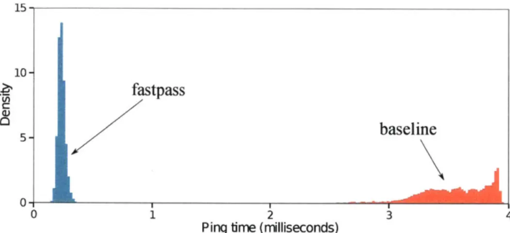
2-6 Histogram of ping RTTs with background load using Fastpass (blue) and baseline (red). Fastpass's RTT is 15.5 x smaller, even with the added overhead of contacting the arbiter. . . . . 52 2-7 Each connection's throughput, with a varying number of senders. Even with Is
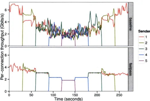
averaging intervals, baseline TCP flows achieve widely varying rates. In contrast, for Fastpass (bottom), with 3, 4, or 5 connections, the throughput curves are on top of one another. The Fastpass max-min fair timeslot allocator maintains fairness at fine granularity. The lower one- and two-sender Fastpass throughput is due to Fastpass qdisc overheads ( 2.7.2). . . . . 53 2-8 As more requests are handled, the NIC polling rate decreases. The resulting
queueing delay can be bounded by distributing request-handling across multiple com m -cores . . . . . 54 2-9 The arbiter requires 0.5 Gbits/s TX and 0.3 Gbits/s RX bandwidth to schedule 150
Gbits/s: around 0.3% of network traffic. . . . . 55 2-10 Path selection routes traffic from 16 racks of 32 endpoints in <12 Ps. Consequently,
10 pathsel-cores would output a routing every <1.2 ps, fast enough to support 10 Gbits/s endpoint links. Error bars show one standard deviation above and below the m ean . . . . 56 2-11 Distribution of the sending and receiving rates of one production server per 100
2-12 99th percentile web request service time vs. server load in production traffic. Fastpass shows a similar latency profile as baseline. . . . . 58 2-13 Live traffic server load as a function of time. Fastpass is shown in the middle with
baseline before and after. The offered load oscillates gently with time. . . . . 59 2-14 Median server TCP retransmission rate during the live experiment. Fastpass
(mid-dle) maintains a 2.5 x lower rate of retransmissions than baseline (left and right).
. ... ... ... 60
3-1 Illustration of how NUM chooses a flow rate. . . . . 64 3-2 Partitioning of network state. . . . . 69 3-3 Aggregation of per-processor LinkBlock state in a 64-processor setup. At the end
of step m, blocks of 2m x 2m processors have aggregated upward LinkBlocks on the main diagonal, and downward LinkBlocks on the secondary diagonal. . . . . 69 3-4 8-to-i experiment on Amazon EC2. Flowtune shares available throughput more
fairly than baseline Linux. . . . . 73
3-5 AWS EC2 data aggregation benchmarks. Flowtune coflows are more predictable and generally faster. . . . . 73 3-6 Flowtune achieves a fair allocation within 100 ps of a new flow arriving or leaving.
In the benchmark, every 10 ms a new flow is added up to 5 flows, then flows finish one by one. DCTCP approaches a fair allocation after several milliseconds. pFabric, as designed, doesn't share the network among flows. sfqCoDel gets a fair allocation quickly, but retransmissions cause the application to observe bursty rates. XCP is conservative in handing out bandwidth and so converges slowly. . . . . 77 3-7 Overhead with Hadoop, cache, and Web workloads is < 0.17%, 0.57%, and 1.13%
of network capacity. . . . . 78 3-8 Notifying servers when rates change by more than a threshold substantially cuts
control traffic volum e . . . . . 79 3-9 The fraction of rate-update traffic remains constant as the network grows from 128
3-10 Improvement in 9 9 th percentile flow completion time with Flowtune. Note the
different scales of the y axis. . . . 80 3-11 Flowtune keeps 2-hop and 4-hop 99th-percentile queuing delays below 8.9 ps. At
0.8 load, XCP has 3.5x longer queues, DCTCP 12x. pFabric and sfqCodel do not maintain FIFO ordering so their p99 queuing delay could not be inferred from sampled queue lengths. . . . 81 3-12 pFabric and sfqCoDel have a significant drop rate (1-in-13 for sfqCoDel). Flowtune,
DCTCP, and XCP drop negligible amounts. . . . 82 3-13 Comparison of proportional fairness of different schemes, i.e., E log2 (rate).
Flow-tune allocates flows closer to their proportional-fair share. . . . 82 3-14 Normalization is necessary; without it, optimization algorithms allocate more than
link capacities. . . . 83 3-15 Normalizing with F-NORM achieves close to optimal throughput, while avoiding
over-capacity allocations. U-NORM's throughput is low in comparison. . . . 84 3.B. 1 CDF of flow size distributions (reproduced from [57]) used in 3.4. . . . 90
List of Tables
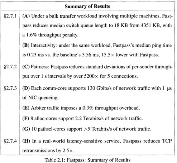
2.1 2.2 2.3 2.4 2.5Fastpass: Summary of Results . . . . Distribution of switch queue lengths in KB. . . . . Latency comparison, Baseline vs. Fastpass. . . . . Throughput variability, Baseline vs. Fastpass. . . . . Throughput of different alloc-core pipelines lengths. . . . . 3.1 NED N otation . . . . 3.2 Flowtune: Summary of Results. . . . . 3.3 Comparison of coflow completion time, Baseline vs. Flowtune. . . 3.4 NED iteration time for different numbers of cores, nodes, and flows. 3.B. 1 Statistics of the different flow size distributions (bytes). . . . .
. . . 49 . . . . 50 . . . . 5 1 . . . . 52 . . . 55 64 72 74 75 90
Chapter 1
Introduction
Many applications today are offered as a service: the application is deployed on compute and storage infrastructure controlled by the serving organization, allowing developers to quickly deploy new features and updates, and to better assure the availability of the service and its associated data in case of failure.
The datacenters hosting these applications are frequently shared infrastructure, hosting many tenants and applications. In the public cloud, applications belong to multiple companies; in the private cloud, different teams and business units. Furthermore, developers partition applications into many components ("microservices"). Microservices allow each component to be developed, deployed and scaled independently, greatly accelerating innovation.
The networks supporting datacenters are also shared, and applications compete for the ability to communicate through the network. When the network fails to allocate the right resources to applications, user experience suffers due to high response times and failure rates. Impaired performance damages user productivity, hurts revenue for companies that sell products online or show advertising, and for any organization, harms the organization's reputation and its ability to retain users.
Each application independently requests the network to transmit its data with unpredictable timing, destinations, and transfer sizes. This makes it hard for a network architecture to effectively manage the way its resources are divided among applications.
Current network architectures are highly distributed: endpoints decide when and how many packets to send ("congestion control"), and switches select packet paths ("routing") and decide
how to mark, drop, and queue packets ("scheduling and queue management"). Because of the strong fault-tolerance and scalability of these distributed architectures, these architectures have been widely adopted as the foundation of the Internet and practically all enterprise networks, and their distributed principles have been engrained into networking research and practice.
However, current architectures also have significant disadvantages. First, with any non-trivial resource allocation policy, configuring the distributed mechanisms at endpointes and switches to achieve desired application outcomes becomes practically impossible, as components interact in subtle ways. Next, the different components interact through the network, so it frequently takes many round-trip times (RTTs) for the network to achieve the desired resource allocation. Finally, changing the network behavior could require reconfiguring every component or in worse cases to replace the deployed mechanisms, which is expensive.
In this thesis we set out to address these disadvantages.
Is it possible to design a network in which: (1) the operator can explicily specify the network's resource allocation policies, (2) the network quickly and consistently enforces these policies, (3) it is easy to deploy, configure, and update network policy, preferrably in software, and (4) the network supports high utilization and low latency?
Such a network would be useful in many contexts, but especially in datacenters where the network is administered by one organization, link rates are at technology's bleeding edge, and system operators have to contend with multiple users and a rich mix of workloads. Meeting complex service-level objectives and application-specific goals would be much easier in a network that delivered these three ideals.
We advocate what may seem like a rather extreme approach: to centrally exercise (very) tight control over when endpoints send packets.
Besides better apportioning resources according to policy, centralized transmission control also solves long standing architectural problems in current networks: queueing latency and packet drops. In current networks, many endpoints can simultaneously burst packets that pass through a single link. To absorb these bursts, network use queues leading to delays that rise and fall and to packet loss when bursts exceed queue capacity.
With tight control, flow rates can match available network capacity over the time-scale of individual packets. Not only will persistent congestion be eliminated, but packet latencies will not
R1 R2
5 ps A 4 Arbiter "A has packet for B"
1-20 ps , timeslot allocation & path selection Arbiter 15 ps Arbiter 4 A "@t=107: A 4 B through R1"
no queuing A 1 B sends data
B A
Figure 1-1: Example allocation of packet transmission from host A to host B in Fastpass.
rise and fall, queues will never vary in size, tail latencies will remain small, and packets will never be dropped due to buffer overflow. Further, networks traditionally control queueing and packet drops by over-provisioning link capacity, leaving a share of capacity unused. Solving queueing and packet drops allows higher utilizations, improving networks cost-efficiency.
Three main concerns arise when considering centralized allocation: 1. Latency. Will allocation excessively delay packets?
2. Scale. How large can centrally allocated clusters be?
3. Fault-tolerance. Can the system gracefully handle controller and switch failure?
This thesis proposes two architectures, Fastpass and Flowtune, and specifies and evaluates solutions that address these concerns.
1.1 Fastpass
Considering the spectrum of network control approaches from the most distributed to the most centralized, Fastpass takes the extreme centralized end: it chooses the exact transmission time and network path of every single packet in the network.
Example. Figure 1-1 shows an example allocation in Fastpass. Say server A wants to send a packet to server B. A first queues the packet and sends a request to the arbiter (shown in red). The arbiter knows about all the packets servers want to send, so it can choose a time and path for the packet such that the packet causes no queueing inside the network: the packet arrives at each switch exactly when its designated output becomes available (yellow). The arbiter informs the server of the allocation (green), and at the designated time, A sends the packet on the allocated path (blue).
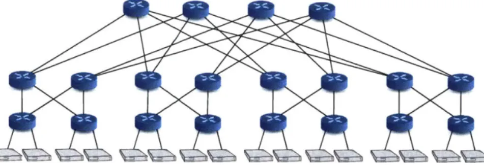
Figure 1-2: Datacenter topologies frequently sport multiple possible paths between endpoints.
Network latencies. The figure also shows example timing for the different steps: transmitting requests and allocations should take 5 Vs and 15 ps respectively, and computation at the arbiter should take 1-20 ps, depending on network size. While allocation adds 20-40 ps for every packet, the major benefit is that once a packet is allocated, it has the ultimate network traversal experience: no queueing and no packet drops. Compared to current networks, the best possible one-way delay in Fastpass is therefore 20-40 ps larger, however under load the average and tail latencies improve dramatically ( 2.7.1). The idea is analogous to a hypothetical road traffic control system in which a central entity tells every vehicle when to depart and which path to take. Then, instead of waiting in traffic, cars can zoom by all the way to their destinations.
But how could an arbiter allocate traffic on a datacenter network? Network transfers start and terminate extremely frequently, and in any non-trivial deployment, it is practically impossible to predict all the tranfers' source, destination, transfer size and timing. Further, common topologies sport multiple paths between most endpoint pairs (figure 1-2); allocation should load-balance traffic across these paths without creating congestion on any particular link.
Timeslots. The first step we took to simplify the problem statement was to divide time into timeslots, in which each source sends to at most one destination, and each destination receives from at most one source. Timeslots discretize the allocator's decisions, as the allocator doesn't need to allocate fractions of a sender's throughput among multiple receivers. Instead, it allocates the entire timeslot to one receiver. The sender can send multiple packets to the receiver - as many as fit in the timeslot. In the prototype, we set timeslot duration to the transmission time of the largest possible packet (an MTU, Maximum Transmission Unit), e.g., 1.2 ps on a 10 Gbits/s network. Timeslots can cause waste due to internal fragmentation; we discuss this in 2.8.4.
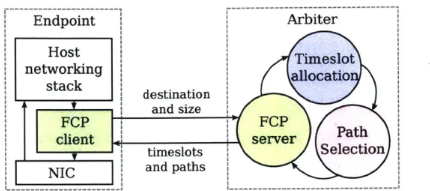
Endpoint Arbiter Host Timeslot networking allocatio stack destination and size FCP FCP
client server Path
Selection
timeslots Secin
..- and paths
Figure 1-3: Structure of the arbiter, showing the timeslot allocator, path selector, and the client-arbiter communication.
Untangling timeslot allocation from path selection. Packet-level control over timing and paths allows the arbiter in the Fastpass architecture to perfectly balance load across the multiple paths available in today's datacenters. Our first implementation jointly chose which endpoints will transmit and the path that transmissions will take: for a given sender-receiver pair, the arbiter traverses all paths between the sender and receiver, and allocates traffic through a path if all links on a path are yet unallocated. This was expensive and hard to scale.
Luckily, a circuit-switching result [36] enables a clean separation of concerns: timeslot allocation can match senders and receivers as if the network is a big switch; then a good path assignment to this allocation is guaranteed to exist. We further found that this path assignment not only exists but can also be efficiently computed: a series of algorithmic advances in edge coloring between 2001-2005 [18, 7, 67] paved the way for the fast edge-coloring implementation in Fastpass ( 2.4).
Fastpass architecture. Figure 1-3 shows the Fastpass architecture. The endpoints queue outgoing packets and send allocation requests to the arbiter. The arbiter performs timeslot allocation and path selection, and notifies endpoints of their allocated timeslots and paths.
Fastpass includes three key components:
1. A timeslot allocation algorithm at the arbiter to determine when each endpoint's packets
should be sent ( 2.2).
2. A path assignment algorithm at the arbiter to assign a path to each packet ( 2.4).
3. A reliable control protocol between endpoints and the arbiter and a replication strategy to
Timeslot allocation. The arbiter runs a heuristic algorithm for maximal matching. To allocate a timeslot, the allocator iterates over endpoint requests, and allocates a source-destination pair if the source and destination are both unallocated in the timeslot. The implementation keeps a bit for every source and for every destination, so checking if a request is possible is an AND of the source and destination bits. To allocate a pair, the code sets both bits to zero and adds an allocation record to an array. These can be implemented very efficiently on commodity CPUs.
Enforcing operator policies. The timeslot allocator iterates over requests to produce a matching. How can it be modified to enforce different operator policies? It turns out that request processing
order matters; different objectives can be achieved with different orderings. For example, Shortest
Remaining Time First (SRTF) can be achieved by first processing requests with the lowest number of remaining timeslots, or max-min fair allocation by first processing the least-recently allocated requests. A re-ordering component sorts requests into priority bins (64 bins in our implementation), and releases these bins in-order to the timeslot allocator. This causes some request delay while requests wait in bins, however policies tend to have limited re-ordering (true for the SRTF and max-min fair policies), so delays are small in practice.
Scaling timeslot allocation. To scale the timeslot allocator, we set out to extend the algorithm to leverage multiple CPU cores. Unfortunately, parallel maximal matching algorithms [8, 47] tend to focus on hardware implementations and are extremely inefficeint on CPUs. Worse, parallel implementation do not preserve the request ordering required for policy enforcement. We realized it is not necessary to speed up a single timeslot allocation. Instead, cores can allocate a set of consecutive timeslots, with each core responsible for a single timeslot. The remaining demand from one timeslot is the input to the next timeslot, forming a pipeline of cores. Cores only need to communicate along the pipeline, and demands are transferred in small batches between cores to reduce overhead.
Are maximal matchings good matchings? The Fastpass timeslot allocator uses a heuristic to find matchings. Before entrusting a datacenter network to such a heuristic, it is important to understand how good (or bad) the produced matchings are. In this work, we bound the maximal matching's average latency by 2x the optimal scheduler's latency on its worse-case workload.1 Figure 1-4
Maximal Matching
Optimal scheduler
with 2C network capacity with C network capacity
Dai-Prabhakar '00:
Finite average latency Finite average latency
This work:
Average latency !2 x Average latency
Figure 1-4: Maximal matchings are good matchings: summary of this work's theoretical contribu-tions in context of prior results.
shows this in the context of related work. Note that this is an upper bound, and in practice, maximal matching tends to perform very well: queueing remains low even at high utilization.
Clock synchronization. The arbiter allocates timeslots such that there is no queueing in the network. To avoid queueing, the endpoints must transmit packets precisely at allocated times. We implemented Fastpass in the Linux kernel using high-precision timers (hrtimers) to time transmitted packets and deployed and configured the IEEE 1588 Precision Time Protocol (PTP) to achieve sub-microsecond network-wide time synchronization. When endpoints are not perfectly synchronized, some queueing results. Fastpass uses switch queues to absorb errors in synchronization. We found queues to be proportional to clock discrepancy and are small in practice (see 2.6.3 and 2.7.1). Relaxing synchronization. While PTP achieves good synchronization results, it was hard to deploy: it requires a carefully tuned configuration and takes many minutes to converge after synchronization disruptions. In later versions of Fastpass, we used arbiter-to-endpoint allocation packets to clock transmissions. Allocation packets experience some jitter, so endpoints do not send precisely at their allocated times. However, the added timing noise is small, and as mentioned above results only in a small amount of queueing ( 2.7.1).
Experimental results. We conducted several experiments with Fastpass running in a portion of Facebook's datacenter network. Our main findings are:
1. High throughput with nearly-zero queues: On a multi-machine (n-to- 1) bulk transfer workload, Fastpass achieved throughput only 1.6% lower than baseline TCP, while reducing the switch queue size from a median of 4.35 Mbytes to under 18 Kbytes. The resulting RTT reduced from 3.56 ms to 230 ps.
2. Consistent (fair) throughput allocation and fast convergence: In a controlled experiment with multiple concurrent flows starting and ending at different times, Fastpass reduced the standard deviation of per-flow throughput by a factor over 5200 x compared to the baseline with five concurrent TCP connections.
3. Scalability: Our implementation of the arbiter shows nearly linear scaling of the allocation algorithm from one to eight cores, with the 8-core allocator handling 184.3M timeslots per second (2.21 Terabits/s on 10 Gbits/s links). The arbiter responds to requests within tens of microseconds even at high load.
4. Reduced retransmissions: On a real-world latency-sensitive service located on the response path for user requests, Fastpass reduced the occurrence of TCP retransmissions by 2.5 x, from between 4 and 5 per second to between 1 and 2 per second.
Added benefit: eliminating incast. Incast occurs when concurrent requests to many servers triggers concurrent responses. With small router queues, response packets are lost, triggering delay-inducing retransmission timeouts [51], whereas large queues cause delays due to queueing. Current solutions are approximations of full control, based on estimates and assumptions about request RTTs, and solve the problem only partially [54, 75]. Fastpass schedules concurrent responses in different timeslots, thereby avoiding loss and retransmission timeouts.
Limitation: scaling. The Fastpass architecture provides very tight control of application network performance, however at the cost of performing per-packet work. Link speeds have been increasing: from 10 Gbits/s networks to 25 Gbits/s, 40 Gbits/s, 100 Gbits/s and beyond. Fastpass is at a disadvantage with increasing link speeds. First, Fastpass could increase its compute power by adding more cores to the pipeline, however this will increase latency, while the networking hardware latencies decrease. Second, Fastpass's pipelining architecture cannot scale indefinitely, as short requests tend to get fulfilled by the head of the pipeline, leaving its tail underutilized.
Limitation: algorithmic design. Fastpass enforces operator policy by re-ordering requests, which requires the policy to be expressed as a algorithm that assigns each request to one of a set of bins; bins are then passed to the timeslot allocator in order. Some policies can be expressed very naturally this way, such as SRTF and max-min fair, however others are harder, especially those pertaining to longer lived flows, where operators would like to control the relative allocation of throughput in different settings, and care less about per-packet latency.
These two limitations motivated us to develop Flowtune.
1.2
Flowtune
Packet-level network resource allocation has become the de facto standard approach to the problem of determining the rates of each flow in a network. Over the past thirty years, network congestion control schemes-whether distributed [39, 14, 33, 31, 70] or centralized [56], whether end-to-end or with switch support [21, 27, 28, 62, 43, 66, 52], and whether in the wide-area Internet [22, 74] or in low-latency datacenters [4, 5, 6, 34, 49]-have operated at the granularity of individual packets. Flowlet-based allocation. In Flowtune, we adopt the position that aflowlet, and not a packet, is a better granularity for congestion control. By "flowlet", we mean the application's transmission granularity: a flowlet starts when a socket has no backlog and an application calls the send () socket call, and ends when there is a threshold amount of time during which the sender's queue is empty. Because application developers care about the network's performance over these send () calls, it is natural to both express and enforce policy over flowlets. Our idea is to compute optimal rates for a set of active flowlets and to update those rates dynamically as flowlets enter and leave the
network.2
Example. Figure 1-5 illustrates an allocation in Flowtune. Whenever a flowlet starts or ends, the endpoint notifies a centralized allocator. Upon receiving each such message, the allocator computes the best values of flow rates for each endpoint according to policy, and updates the endpoints.
NUM. Flowtune adopts the network utility maximization (NUM) framework, previously developed to analyze distributed congestion control protocols [44, 46]. In Flowtune, network operators specify
explicit utility functions, and the allocator maximizes the total network utility.
Allocation complexity. With flowlet-based allocation, the network can avoid per-packet work, as rates would have to change only when new flows arrive or flows leave the system. However, computing the optimal rates is difficult because even one flowlet arriving or leaving could, in general, cause updates to the rates of many existing flows. Flows that share a bottleneck with the new or ending flow would change their rates. But, in addition, if some of these flows slow down, other flows elsewhere in the network might be able to speed up, and so on. The effects can cascade.
2
RI R2
Hadoop on Server A has data for B:
Allocator A 4 Allocator "Hadoop on A has data for B"
Assign rates Allocator 4 A "Send at 40Gbps"
B C A
(a) The allocator assigns rates to flowlets. When links are free, flowlets are instructed to immediately ramp up to line rate.
R1 R2
Now say adserver on Server C has data for B:
C 4 Allocator "adserver on C has data for B"
Allocator katr Assign rates
Allocator - A "Send at 5Gbps" Allocator 4 C "Send at 35Gbps"
B C A
(b) When a new flowlet arrives, the allocator re-assigns rates according to policy. Figure 1-5: Example of allocation in Flowtune.
NED. To converge quickly to the allocation that maximizes the specified utility, we introduce a new method, termed Newton-Exact-Diagonal (NED). Iterative solvers to NUM make incremental adjustments to rates (Figure 1-6). NED leverages the explicit knowledge of the operator's utility functions to adjust how aggressive each iteration's updates should be (Figure 1-7, 3.1).
Flowtune can achieve a variety of desirable objectives. In this work, we focus on proportional fairness, i.e., max E; U(xi), where U(xi) = log xi, and xi is the throughput of flowlet i. In general, however, NED supports any objective where the utility is a function of the flow's allocated rate.3 A responsive architecture. Traditionally, an optimizer would run iterations until the solution converges before setting rates (Figure 1-8a), causing large delays in rate updates when flowlets start or end. To increase system responsiveness, the allocator continuously updates its set of active flowlets and publishes intermediate rates between iterations of the optimizer (Figure 1-8b). These intermediate rates may temporarily exceed the capacity of some links, causing queuing delays. To reduce queuing, Flowtune uses a rate normalizer (F-NORM, 3.2) to scale-down the computed values (Figure 1-8c).
3
.100-W
0
0.005 0.010 0.015 0.020
link price
Figure 1-6: Iterative solvers to NUM adjust rates via prices. Too small adjustment result in slow convergence; too aggresive updates result in oscillation and failure to converge.
100-0.005 0.010 0.015 0.020
link price
Figure 1-7: NED uses the slope of the explicit utility functions to choose the size of incremental updates, similar to the Newton method, requiring fewer updates to converge.
The normalizer's results are sent to the endpoints. Endpoints transmit according to these rates (they are trusted, similar to trust in TCP transmissions today). Figure 1-9 shows the system components and their interactions.
Flowtune does not select flow paths, but rather works given the paths the network selects for each flow ( 3.5).
Cache-aware multicore architecture. A scalable implementation of the optimization algorithm on CPUs would run in parallel on multiple cores. Unfortunately, straightforward implementations are slowed by expensive cache-coherence traffic. We propose a partitioning of flows to cores where each core only interacts with a small set of links. Each core has copies of link state it needs. Before manipulating link state, the algorithm aggregates all modified copies of link state to authoritative copies. Afterwards, the algorithm distributes copies back to the cores ( 3.3). On 40 Gbits/s links,
Update Run 100 Output
inputs iterations rates
(a) The strawman solution runs the optimizer until it converges, but then system is slow to react to updates of flowlet start/end.
Update Run 1 Output
inputs iteration rates
(b) Performing just one iteration reduces reaction time, but results in over-allocation while the algorithm converges.
Update Run 1 Normalize Output
inputs iteration rates rates
(c) Flowtune adds a normalization step that eliminates link over-allocation while achieving 99.7% of optimal throughput.
Figure 1-8: Motivation for the allocator architecture.
this scheme allows our implementation to allocate 15.36 Tbit/s in 8.29 on 4 Nehalem cores, up to 184 Thit/s in 30.71 ps on 64 Nehalem cores ( 3.4.2).
Implementation and Evaluation. We implemented Flowtune in a Linux kernel module and a C++ allocator that implements the multi-core NED algorithm and uses kernel-bypass for NIC access. The system enforces rate allocations on unmodified Linux applications. We deployed Flowtune on Amazon Web Services instances; experiments show the servers are able to achieve their fair share of available network resources, with much better fairness than the Linux baseline (which uses Cubic). Flowtune reduced the 95th percentile (p95) of coflow completion times [17] by 1.61 x on a data aggregation benchmark.
Simulation results show that Flowtune out-performs distributed congestion control methods like DCTCP, pFabric, Cubic-over-sfqCoDel, and XCP on metrics of interest like the convergence time and the p99 of the flow completion time (FCT).
Compared with the centralized arbitration in Fastpass [56], Flowtune offers similar fast con-vergence, but handles 10.4x traffic per core and utilizes 8 x more cores, for an improvement in throughput by a factor of 83.2.
, . ... lw e . N ED start/end NED ...-.---... Endpoint flow routes''--.. rates(periodically) Endpoint F-NORMnfllledEdot ... Endpoint Allocator
Figure 1-9: Flowtune components. Endpoints send notifications of new flowlets starting and current flowlets finishing to the allocator. The NED optimizer computes rates, which F-NORM then normalizes and sends back to Endpoints; endpoints adjust sending rates accordingly.
Congestion Update routing
Flow control control tables
Congestion Update routing
Flow control control tables
Congestion Update routing
Flow control control tables Congestion Per-packet path Flow control control selection
Scheduling & Queue mgmt. Scheduling & Queue mgmt. Scheduling & Queue mgmt. Scheduling & Queue mgmt. Centralized
Figure 1-10: Responsibilities for
Fastpass architectures.
networking activities in the traditional, SDN, Flowtune and
1.3 The bigger picture
Figure 1-10 compares Flowtune and Fastpass to the two major network architectures: traditional networking and Software Defined Networks (SDN). In traditional networks, the endpoint chooses when and how many packets to send (flow control and congestion control), and switches choose the routes packet take, decide how to schedule queued packets, and perform the actual packet forwarding. Traditional SDN Flowtune Fastpass Packet forwarding Packet forwarding Packet forwarding Packet forwarding Switch
SDN centralizes the control plane: the choice of routes is delegated to a centralized con-troller. The controller makes decisions when flows start or in some proposals at coarse granularity periodically (every few minutes or seconds).
Flowtune centralizes endpoint congestion control and switch scheduling and queue management, giving the allocator control over resource allocation with data-plane granularity. Control over routing is left to other mechanisms, whether distributed or centralized.
Fastpass further centralizes routing, and provides packet-granularity scheduling and routing control, further extracting functionality from switches.
Switches can become much simpler. With Fastpass and Flowtune, switches need to implement less functionality, so switches for these architectures can be simpler and cheaper. Further, with simplified functionality, it should be easier to scale switches to the next generations of link speeds. Better developer productivity. In the Flowtune and Fastpass architectures, developers need not worry about packet drops, high tail latency, and hotspots delaying traffic, and in Fastpass, do not need to avoid bursts. These stronger network-provided semantics simplify application building and debugging, improving developer productivity.
Better datacenter operations. Flowtune and Fastpass give operators tools to better balance the needs of the different applications and ensure applications' peaceful co-existence. Further, networks can run at higher utilizations without excessive queueing and packet loss, which reduces the cost/performance ratio.
Guiding principal: explicit policy. Both architectures presented in this work let operators explic-itly specify policy of how network resources should be allocated. We believe explicit policy will help application developers and network engineers reason about and enforce performance goals, thus bridge the communication chasm between the two disciplines. We hope the explicit policy enforcement proposed by this work will help service providers run their datacenter networks - and improve online service quality for all.
1.4 Contributions
1.4.1
Fastpass
1. A timeslot-based networking architecture for datacenters, with per-timeslot control of allowed sender-receiver pairs and packet paths.
2. A method to use maximal matching to achieve operator objectives by re-ordering input requests. An O(1) insertion and pop data structure for re-ordering requests. Algorithms to achieve SRTF and max-min fair allocations using re-oredering. Fast implementations of the re-ordering, maximal matching, SRTF, and max-min fair algorithms on CPU.
3. A proof that bounds the maximal-matching average latency by 2 x that of the optimal allo-cation's (with the standard 2x speedup common in such proofs). Best previous result only shows that maximal-matching latencies are bounded if optimal latencies are bounded. 4. A technique to scale timeslot allocation by arranging timeslot allocation cores into a pipeline
and passing requests between cores in batches to reduce overhead. A multicore architecture which allows scaling communication, timeslot allocation, and path selection independently (comm-, alloc- and pathsel-cores), and a specification of how the core types communicate. A C++ implementation using DPDK cores and rings.
5. Adaptation of a circuit-switching technique to allocate paths given allocated matchings [36] to packet-switched networks, where updates are expected to be 4-5 orders of magnitude more frequent. A fast implementation of edge-coloring for path selection on CPUs.
6. A reliable, low-latency protocol for requests and allocations using idempotent updates (the Fastpass Control Protocol, FCP). A low-overhead implementation of FCP.
7. A hot backup failover technique for fault tolerance in case of Arbiter failure, and its imple-mentation.
8. Evaluation using microbenchmarks, synthetic experiments in a datacenter, and Facebook production traffic.
9. An open-source distribution of the Fastpass code under a permissive license (MIT license). Our source code is at http: / / f astpas s .mit .edu /.
1.4.2
Flowtune
1. Flowlet-based allocation, where the network allocates resources to application-layer trans-mission batches (flowlets), and an architecture for centrally assigning rates to flowlets. 2. The Newton-Exact-Diagonal (NED) algorithm for solving the Network Utility Maximization
(NUM) problem with fast convergence times.
3. An architecture that allows the network allocator to output rates before full convergence while avoiding queueing and packet loss by introducing a normalizer. Two normalizer algorithms: U-NORM and F-NORM, their implementation and evaluation.
4. A multicore algorithm required to efficiently move between computation on flows to compu-tation on links on modem CPUs, replacing random-access memory patterns with sequential scans. Fast multicore implementations of NED and F-NORM using this algorithm.
5. A Linux kernel implementation of flowlet scheduling and an idempotent protocol on top of FCP. A C++ controller using DPDK.
6. Evaluation using ns-2 simulation, microbenchmarks, numeric simulation, and a deployment on Amazon EC2.
Chapter 2
Fastpass: Packet-based Allocation
2.1
Fastpass Architecture
In Fastpass, a logically centralized arbiter controls all network transfers (Fig. 1-3). When an application calls sendo or sendtoo on a socket, the operating system sends this demand in a request message to the Fastpass arbiter, specifying the destination and the number of bytes. The arbiter processes each request, performing two functions:
1. Timeslot allocation: Assign the requester a set of timeslots in which to transmit this data. The granularity of a timeslot is the time taken to transmit a single MTU-sized packet over the fastest link connecting an endpoint to the network. The arbiter keeps track of the source-destination pairs assigned each timeslot ( 2.2).
2. Path selection. The arbiter also chooses a path through the network for each packet and communicates this information to the requesting source ( 2.4).
Because the arbiter knows about all current and scheduled transfers, it can choose timeslots and paths that yield the "zero-queue" property: the arbiter arranges for each packet to arrive at a switch on the path just as the next link to the destination becomes available.
The arbiter must achieve high throughput and low latency for both these functions; a single arbiter must be able to allocate traffic for a network with thousands of endpoints within a few timeslots.
Endpoints communicate with the arbiter using the Fastpass Control Protocol (FCP) ( 2.5.3). FCP is a reliable protocol that conveys the demands of a sending endpoint to the arbiter and the
allocated timeslot and paths back to the sender. FCP must balance conflicting requirements: it must consume only a small fraction of network bandwidth, achieve low latency, and handle packet drops and arbiter failure without interrupting endpoint communication. FCP provides reliability using timeouts and ACKs of aggregate demands and allocations.
Endpoint applications can send many megabytes with one send () socket call, and can make many send () s in quick succession. Endpoints aggregate allocation demands over a few microsec-onds into each request packet sent to the arbiter. This aggregation reduces the overhead of requests, and limits queuing at the arbiter.
Fastpass can recover from faults with little disruption to the network ( 2.5). Because switch buffer occupancy is small, packet loss is rare and can be used as an indication of component failure. Endpoints report packet losses to the arbiter, which uses these reports to isolate faulty links or switches and compute fault-free paths. The arbiter itself maintains only soft state and endpoints retransmit aggressively if the arbiter does not respond (lOs of microseconds), so that a secondary arbiter can take over within a few milliseconds if the primary arbiter fails.
To achieve the ideal of zero queueing, Fastpass requires precise timing across the endpoints and switches in the network. When endpoint transmissions occur outside their allocated timeslots, packets from multiple allocated timeslots might arrive at a switch at the same time, resulting in queueing. Queueing is linear in the clock discrepancy and is small in practice (see 2.6.3, 2.7.1)
Fastpass requires no switch modifications, nor the use of any advanced switch features. End-points require some hardware support in NICs that is currently available in commodity hardware ( 2.6.3), with protocol support in the operating system. Arbiters can be ordinary server-class machines, but to handle very large clusters, a number of high-speed ports would be required.
2.1.1
Latency experienced by packets in Fastpass
In an ideal version of Fastpass, endpoints receive allocations as soon as they request them: the latency of communication with the arbiter and the time to compute timeslots and paths would be zero. In this ideal case, the end-to-end latency of a packet transmission would be the time until the allocated timeslot plus the time needed for the packet to traverse the path to the receiver with empty queues at all egress ports.
In moderately-loaded to heavily-loaded networks, packets are delayed at their endpoints while previously-allocated packets are transmitted. This causes the ideal allocations mentioned above to typically be several timeslots in the future. As long as the Fastpass arbiter returns results in less than the several timeslots, Fastpass would achieve the ideal minimum packet latency in practice too.
In lightly-loaded networks, Fastpass trades off a slight degradation in the mean packet latency (due to communication with the arbiter) for a significant reduction in the tail packet latency.
2.1.2
Deploying Fastpass
Fastpass is deployable incrementally in a datacenter network. Communication to endpoints outside the Fastpass boundary (e.g., to hosts in a non-Fastpass subnet or on the Internet) uses Fastpass to reach the boundary, and is then carried by the external network. Incoming traffic either passes through gateways or travels in a lower priority class. Gateways receive packets from outside the boundary, and use Fastpass to send them within the boundary. Alternatively, incoming packets may use a lower-priority class to avoid inflating network queues for Fastpass traffic.
This chapter focuses on deployments where a single arbiter is responsible for all traffic within the deployment boundary. We discuss larger deployments in 2.8.1.
2.2
Timeslot Allocation
The goal of the arbiter's timeslot allocation algorithm is to choose a matching of endpoints in each timeslot, i.e., a set of sender-receiver endpoint pairs that can communicate in a timeslot. For a simpler exposition, we assume here that all endpoint links run at the same rate. The demand for any given link in the network can exceed its capacity; the arbiter selects sender-receiver pairs and assigns a path to packets (described in 2.4) to ensure that traffic issued in a given timeslot will not exceed any link's bandwidth.
Networks are often organized into tiers, with each tier providing network transport to components below it: top-of-rack switches connect servers in a rack, aggregation switches connect racks into clusters, core routers connect clusters (Figure 1-2). Fastpass requires that tiers be rearrangeably
non blocking (RNB) [23], networks where any traffic that satisfies the input and output bandwidth
The RNB property allows the arbiter to perform timeslot allocation separately from path selection: by definition, as long as the allocated matching satisfies the bandwidth constraints in and out of each tier, path selection is guaranteed to successfully assign paths on the physical topology. Consequently, each tier can be abstracted as a single switch for the purpose of timeslot allocation.1 The result is a tree topology on which it is easy for timeslot allocation to check bandwidth constraints, even when the physical network is oversubscribed and has many paths between endpoints. Non-oversubscribed (full-bisection bandwidth) topologies [2, 29, 53, 76] can be abstracted further: we can view the entire network as a single switch.
Because the arbiter has knowledge of all endpoint demands, it can allocate traffic according to global policies that would be harder to enforce in a distributed setting. For instance, the arbiter can allocate timeslots to achieve max-min fairness, to minimize flow completion time, or to limit the aggregate throughput of certain classes of traffic. When conditions change, the network does not need to converge to a good allocation - the arbiter can change the allocation from one timeslot to the next. As a result, the policy (e.g., fairness) can be achieved even over short time scales.
How fast must a viable allocation algorithm be? At first glance, endpoint link speeds determine the allowed allocator runtime, since the arbiter's processing rate must match endpoint link speed. On 10 Gbits/s links with 1500-byte timeslots, a timeslot is 1.2 ps; the arbiter must allocate a timeslot every 1.2 ps, leaving very few compute cycles for allocating each timeslot. However, this can be improved by allocating multiple timeslots in parallel: say 10 cores allocate 10 timeslots in parallel. If each core takes 12 ps to compute its allocation (10 x more cycles), in aggregate the arbiter can still finish one allocation per 1.2 ps, maintaining the required processing rate.
A long runtime per timeslot (compared to the minimum RTT between the endpoints) is ac-ceptable with some workloads, but not others: on heavily-loaded endpoints, the time until the first available timeslot can be tens to hundreds of microseconds, so traffic will observe the ideal end-to-end latency ( 2.1.1), even if allocation takes many microseconds. On the other hand, traffic on lightly-loaded networks doesn't enjoy this masking of allocation latency; the algorithm must finish promptly if a small end-to-end latency increase is desired.
Complete knowledge of all network demands thus becomes a double-edged sword; in order to meet these latency and throughput requirements, the timeslot allocator requires very fast algorithms.
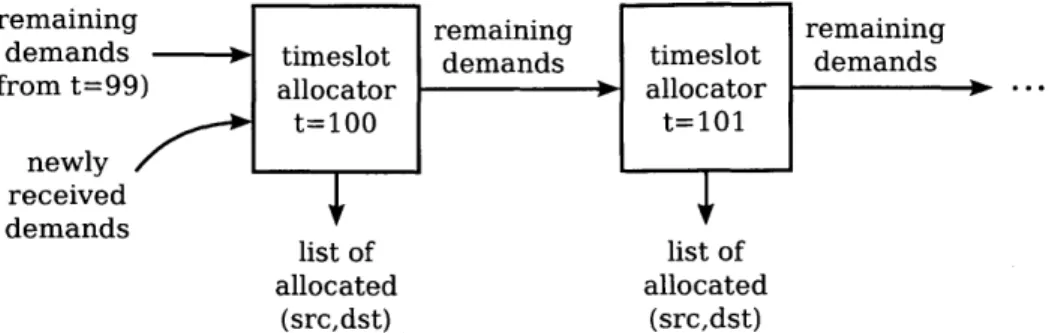
remaining remaining remaining
demands 0 timeslot demands timeslot demands
(from t=99) allocator allocator
nely/_ lt=100 It=101 _ newly received demands list of list of allocated allocated (src,dst) (src,dst)
Figure 2-1: Pipelined timeslot allocation. The allocator for timeslot t processes the demands not fully satisfied by the allocator for t - 1
Finding an allocation with the largest possible number of pairs (a maximum matching) is expensive; switch algorithms (e.g., [69, 9, 47]) generally use heuristics to find good, but not maximum, matchings. Fastpass uses a similar approach: as the arbiter processes demands, it greedily allocates a source-destination pair if allocating the pair does not violate bandwidth constraints.2 When the arbiter finishes processing all demands, it has a maximal matching, a matching in which
none of the unallocated demands can be allocated while maintaining the bandwidth constraints.
2.2.1
A pipelined allocator
The allocator takes a list of all network demands (how many timeslots are waiting to be sent between each pair of endpoints), and computes the allocated matching and the remaining demands after the allocation. Figure 2-1 shows how Fastpass allocators are arranged into a pipeline: the input to the allocator processing timeslot t is the remaining demand after allocating timeslot t - 1. Cores do not wait to process all input demands before outputting remaining demands. Instead, cores output each remaining demand soon after processing it. Demands stream between the running cores, allowing multiple cores to perform useful work concurrently.
The arbiter implements different allocation policies by changing the order in which demands are processed. For max-min fairness, the arbiter orders demands by the last timeslot that was allocated to the source-destination pair, "least recently allocated first"; for minimizing flow completion time
2
1n a non-oversubscribed network, the arbiter checks that neither the source nor the destination have already been allocated to a different pair. Oversubscribed topologies require the arbiter to additionally check bandwidth constraints in and out of each network tier.
active flows
src
dst
1
1
2
2
3
3
4
4
Figure 2-2: Timeslotlast
allocated
src dst allocation
srcs & dsts
1
3
45
o---
--
]/
4
2
47
EI-]QL]
-
/
2
3
48
MIULI
X
2
1
48
i
/
3
4
51
allocation for the max-min fairness allocation objective.
(min-FCT), the arbiter tracks the number of pending bytes (measured in MTU-sized chunks) and performs "fewest remaining MTUs first".
Figure 2-2 demonstrates the allocation of one timeslot in a simple network with four endpoints. The allocator orders the demands by the last timeslot allocated to each pair, and processes them in that order. On the right is the state used to track bandwidth constraints: one bit for each source and for each destination. The first two demands can be allocated because both the source and destination are available, but the third demand cannot be allocated because destination 3 has already been allocated. The remaining two demands can be allocated, yielding a maximal matching.
Each allocator in the pipeline receives a stream of demands. Ideally, an allocator could process each demand as soon as it is produced by the previous allocator. If demands can appear out of the desired order, however, the allocator must reorder them first. In a worst-case scenario, the last demand from the previous allocator should be processed first. The allocator would have to wait until the previous allocator produced all demands in the stream before it could start processing, eliminating the concurrency gained by pipelining.
Fortunately, with both max-min fairness and min-FCT (and other such objectives), demands can be kept in roughly the correct order with only limited reordering. For example, in max-min fairness, the allocator of timeslot t only changes the last allocated timeslot of a source-destination pair if that pair is allocated, and will only change it to t. Therefore, an allocator for timeslot t + I can process all demands with last allocated timeslot strictly less than t immediately. Only demands with last allocated timeslot equal to t need to be kept until all demands are received.