HAL Id: hal-02356090
https://hal.laas.fr/hal-02356090
Submitted on 10 Apr 2020
HAL is a multi-disciplinary open access
archive for the deposit and dissemination of
sci-entific research documents, whether they are
pub-lished or not. The documents may come from
teaching and research institutions in France or
abroad, or from public or private research centers.
L’archive ouverte pluridisciplinaire HAL, est
destinée au dépôt et à la diffusion de documents
scientifiques de niveau recherche, publiés ou non,
émanant des établissements d’enseignement et de
recherche français ou étrangers, des laboratoires
publics ou privés.
advances for laser wavelength stabilization and enhanced
second harmonic generation
Antoine Monmayrant, Olivier Gauthier-Lafaye, Stéphane Calvez, François
Renaud, Evgueni Popov, Anne-Laure Fehrembach
To cite this version:
Antoine Monmayrant, Olivier Gauthier-Lafaye, Stéphane Calvez, François Renaud, Evgueni Popov,
et al.. Cavity Resonator Integrated Grating Filters : recent advances for laser wavelength stabilization
and enhanced second harmonic generation. The Thirteenth International Conference on Quantum,
Nano/Bio, and Micro Technologies (ICQNM 2019), IARIA, Oct 2019, Nice, France. �hal-02356090�
Cavity Resonator Integrated Grating Filters :
Recent Advances for Laser Wavelength Stabilization
and Enhanced Second Harmonic Generation
Antoine Monmayrant,
Olivier Gauthier-Lafaye,
St´ephane Calvez
LAAS-CNRS, Universit´e de Toulouse, CNRS, F-31400 Toulouse, France email: [email protected] email: [email protected] email: [email protected]Franc¸ois Renaud,
Anne-Laure Fehrembach,
Evgueni Popov
Aix Marseille Univ, CNRS Centrale Marseille, Institut Fresnel,
F-13013 Marseille, France email: [email protected] email: [email protected]
email: [email protected]
Abstract—Cavity Resonator Integrated Grating Filters (CRIGFs) are a peculiar mix between microcavities and Guided-Mode Resonant Filters (GMRFs). They rely on the coupling of free-space beams to guided and localized modes in a multilayer structure by subwavelength gratings. They provide spectrally selective reflection for tightly focussed beams, combining high Q-factors with high angular and positioning tolerances. Recently, their unusual properties have been harnessed to design and demonstrate compact and robust Extended Cavity Diode Lasers (ECDL) with single-mode and narrow-linewidth emission in the near infrared and Extended Cavity Quantum Cascade Lasers (ECQCL) with tunable emission in the mid-infrared. More recent works have taken advantage of new geometries on thermo-optic and non-linear material to demonstrate thermal tuning and second harmonic generation at telecom wavelengths. In this contribution, the principle and key features of CRIGFs will be presented together with the applications listed above.
Keywords–Bragg gratings; nanophotonics; optical filters.
I. INTRODUCTION
Cavity Resonator Integrated Grating Filters (CRIGFs) have been introduced a few years ago as small aperture spectral filters [1]. Contrary to the Guided-Mode Resonant Filters (GMRFs) they are derived from, they exhibit large angular acceptance together with a filtered wavelength that does not depend on the conditions of incidence [2][3]. This opens the way to new geometries for extended cavities to stabilize the emitted wavelength of different kinds of lasers [4][5]. Here, we will report on recent advances on the CRIGF-based extended cavity diode laser and quantum cascade lasers.
The rest of the paper is structured as follows. Section II presents the main theoretical differences between CRIGFs and the more widespread GMRFs. Section III presents the use of CRIGFs for wavelength stabilization in extended cavities for both diode lasers (in the near infrared) and quantum cascade lasers (in the mid-infrared). Section IV details the recent approaches for wavelength tuning of CRIGFs, which are inherently fixed wavelength filters. We conclude our work in Section V.
II. GMRFS ANDCRIGFS THEORY
A. GMRFs
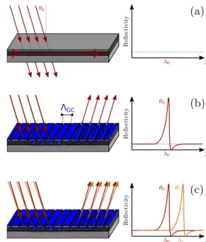
GMRFs are based on the coupling of guided modes and propagating waves through Bragg gratings, usually called Grating Couplers (GCs). As described in Figure 1 (a), GMRFs are commonly based on a multistack layer that plays a double role around the wavelength of interest λ0 and the angle of
incidence of interest θ0: (1) they act as an antireflection coating
for incoming propagating waves; (2) they contain a single-mode planar waveguide (usually for TE guided-single-mode).
ΛGC
Figure 1. Principle of GMRFs: (a) base antireflection multistack layer; (b) grating coupler and Fano reflection spectrum; (c) angular tuning of the
spectrum.
The GC is designed such that it couples the incoming propagating waves to the guided-mode at the wavelength of
interest λ0 (see Figure 1 (b)). Out of resonance (i.e., away
from λ0), the reflectivity of the multistack is unaffected and
stays low. At resonance, the incoming wave is simultaneously coupled into the waveguide and decoupled into the specular direction (see Figure 1 (b)). In the specular direction, this results in a Fano-shaped resonant spectrum that adds to the low reflectivity background. As the coupling condition of the incoming wave to the guided mode by the GC depends on the angle (Bragg condition), the spectral response can be tuned by changing the angle of incidence (see Figure 1 (c)), with a quasi-linear tuning for angles away from normal incidence (and quadratic tuning near normal incidence). The main design parameters of the GMRF (once the multistack and thus the waveguide are set) are the periodicity ΛGC of the GC and
its filling factor. The filling factor alters the width of the Fano resonance: the sharpest resonances are obtained for filling factors of 0.5 and the width of the resonance increases as we move away from 0.5. For a given angle of incidence and a given guided mode, the periodicity ΛGC sets the wavelength
of resonance λ0. If we neglect the chromatic dispersion of the
waveguide, λ0 scales linearly with the periodicity of the GC.
One noticeable consequence of the angular tuning is the lack of angular tolerance of GMRFs with Q factors. For a high-Q factor GMRF, the spectral Fano peak is extremely narrow, and because of the linear angular tuning, this corresponds to a narrow angular tolerance. As a result, a high-Q GMRF results in a narrow spectral peak with high reflectivity only if (1) the incoming beam is large enough, with a flat phase-front (i.e., really close to an ideal plane wave); (2) the GMRF is large enough and perfectly uniform across its whole area. Any deviation from this ideal case results in reduced performance [6].
B. CRIGFs
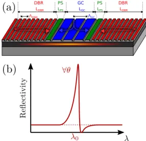
CRIGFs [1] are a variation around the concept of GMRFs. The base idea was to provide the same kind of spectral high-Q filter, but with a smaller footprint. The base geometry is depicted on Figure 2 (a).
LPS ΛDBR LDBR ΛGC LGC LPS LDBR DBR GC PS PS DBR
Figure 2. Principle of CRIGFs: (a) Schematic view of a CRIGF (b) Typical spectral reflectivity.
A small grating coupler (GC, in blue) of typically a few to a few tens of periods ΛGC is sided by two unstructured Phase
Sections (PS, in green) and two Distributed Bragg Reflectors (DBR, in red). The pair of DBRs forms a planar Fabry-P´erot cavity that supports several modes, all localized under the GC. By adjusting the length LP S of the phase section, one
can ensure that one of these modes is spectrally overlapped with the Bragg resonance of the GC. When this is the case, a beam tightly focussed to the dimension LGCof the GC, under
normal incidence, can couple to this localized mode and re-emits along both the reflected and transmitted directions. As shown in Figure 2 (b), this coupling and re-emission results in one single Fano resonance at the wavelength of interest λ0. Contrary to GMRFs, this spectrum is not tunable with the
angle of incidence, the spectral reflectivity being set once and for all [7]. In particular, contrary to GMRFs where spectral and angular width are totally coupled, the CRIGF spectral width is decoupled from its angular acceptance. High-Q CRIGFs with large angular tolerances have been demonstrated [2]. Moreover, another distinction is that neither the spectral width, nor the spectral position of the resonance are affected by the conditions of incidence on the CRIGF [2][3]. The only parameter affected is the peak reflectivity that is maximized when the beam is spatially overlapped with the GC and when its size matches LGC. One can thus tailor the size LGC of the
GC at the centre of the CRIGF to match that of the targeted focussed beam independently from the wavelength of interest and spectral width. One particular advantage of the CRIGF is its large tolerance [2] for both angular (several degrees) and positional (from few µm to few 100µm) degrees of freedom. One last property of the CRIGF that helps integrate several CRIGFs with different reflected wavelengths on a same sub-strate is that every critical dimension is directly proportional to the GC periodicity ΛGC. Indeed, the DBR periodicity is
ΛDBR = 1/2ΛGC and the optimal PS length was found to
be LP S = 1.125ΛGC (see reference [2]). As the wavelength
of interest λ0 is proportional to the GC periodicity ΛGC,
it is straightforward to design several CRIGFs at different wavelengths: one just needs to scale all the planar dimensions of the CRIGF (i.e., ΛGC, ΛDBR, LP S) uniformly.
III. CRIGFS FOR LASER WAVELENGTH STABILIZATION
A. Extended Cavity Diode Laser in the near infrared
One application of CRIGFs is the conception of minimalist Extended Cavity Diode Lasers (ECDLs), as reported in [4]. The goal of an ECDL is to enhance the spectral purity of a diode laser. The base principle of ECDL is two-fold: (1) the Fabry-P´erot cavity extends the laser beyond the length of the diode laser chip and thus decreases the spectral width of each Fabry-P´erot mode ; (2) a spectral filtering element introduced in the cavity further reduces the spectral width and selects one isolated mode. The ECDL is usually quite complex, tricky to align and not robust towards misalignment and vibrations, for two reasons. First, the ECDL contains many independent components (gain chip, several intracavity lenses, a spectral filter, an end reflector) that should all be carefully aligned. This makes the cavity more complex: more elements in the cavity means more elements to align and a reduction of the robustness of the cavity as each element is a possible point of failure. Second, most usual spectral filters with a high Q-factor (i.e., a low spectral width) only work efficiently on well collimated beams. The highly divergent output of the diode laser gain chip thus needs to be carefully collimated intracavity before
reaching the filtering element (as in the Littrow configuration, for example). This geometry is particularly sensitive to angular misalignment of the filter that hinders the optical feedback into the gain chip.
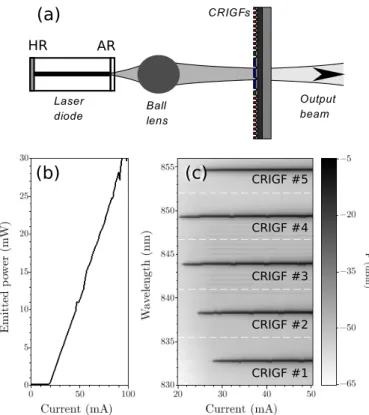
AR HR
(a)
CRIGF #1 CRIGF #2 CRIGF #3 CRIGF #4 CRIGF #5(b)
(c)
Figure 3. ECDL wavelength stabilization with CRIGFs: (a) schematic of the minimalist cavity; (b) Typical light curve; (c) Spectrum as a function of the
injected current for 5 different CRIGFs.
As shown in Figure 3 (a), a CRIGF-based ECDL can be simpler than an usual ECDL. First, as the CRIGF acts simultaneously as the end reflector and the optical filter, the cavity only contains 3 elements: a gain chip, an imaging lens and the CRIGF. This reduces the number of elements in the ECDL and thus decreases the chances of failure. Second, as the CRIGF can work with tightly focused beams, the cavity has a so-called “cat’s-eye” geometry where the anti-reflection-coated facet of the gain chip (AR) is imaged onto the CRIGF that plays the role of a spectrally selective end reflector. This geometry is more robust towards angular displacement of the end reflector.
Figure 3 (b) shows a typical light curve (emitted power as a function of the injected current in the diode laser gain chip) for a CRIGF-based ECDL operating around 850 nm: thresholds around 20 mA and emitted power up to 30 mW are routinely achieved [4]. As can be seen in Figure 3 (c) that shows the emitted spectrum of the CRIGF-based ECDL as a function of the injected current for 5 different CRIGFs, depending on the spectral peak reflectivity of the CRIGF used, the emitted wavelength can be stabilized around any wavelength in the spectral gain of the diode laser. From Figure 3 (c), one can observe the detuning between the stabilization wavelength set by the CRIGF and the spectral gain of the diode laser: the higher the detuning, the higher the threshold. The smallest detuning is around 850 nm (the smallest threshold).
Current works in this field are focussing on miniaturization
of the cavity to fit all components in a butterfly package and on the achievement of low-linewidth emission [8] (few 100 kHz linewidth).
B. Extended Cavity Quantum Cascade Laser in the mid-infrared
The stabilization of laser diodes described previously can be easily extended towards other wavelength ranges, like the mid-infrared. Indeed, there is nothing that is wavelength specific in the principle of CRIGFs. Provided that we find suitable materials (i.e., materials that we can process in a clean room and with appropriate refractive index and low absorp-tion), we can design and fabricate CRIGFs in any wavelength ranges. In the mid-infrared, CRIGFs were demonstrated using GaAs/GaAlAs material system [5]. As presented in Figure 4, the geometry is exactly the same than in the near infrared. The only differences are due to the different wavelength range of operation: the gain chip is a quantum cascade gain chip, the optics are made of ZnSe and the CRIGF is GaAs/GaAlAs.
IntraCavity Lens
Figure 4. Extended cavity quantum cascade laser.
Figure 5 shows the spectrum emitted by the cavity as a function of the periodicity of the CRIGF used for stabilization. Each periodicity results in a particular wavelength reflected by the CRIGF. When the reflected wavelength is not too far detuned from the spectral gain of the quantum cascade gain chip (periodicity in the range [1460:1510] from red to light blue in Figure 5), the emission is stabilized to the reflected wavelength. When the detuning is too large (periodicity in the range [1520:1560] from blue to purple in Figure 5), the cavity emits around the maximum of the spectral gain and the emission is not stabilized.
IV. TUNABLECRIGFS:SPATIAL AND THERMAL TUNING
The main advantage of the CRIGFs (the reflected wave-length not depending on the conditions of incidence) is also a main disadvantage for some applications: the CRIGF is inherently non-tunable. Indeed, for both ECDL and ECQCL, in addition to wavelength stabilization, wavelength tuning would be beneficial. Two approaches have been followed. The first one takes advantage of the 2D nature of the CRIGF. As can be seen in Figure 2 (a), the CRIGF is invariant along the grooves of the GC and DBRs: along this dimension, the CRIGF can be arbitrarily long without noticeably changing the CRIGF properties. As the spectral reflectivity of the CRIGF is directly given by the planar dimensions (ΛGC, ΛDBR, LP S), one can
2 200 2 100 2 120 2 140 2 160 2 180 2 090 2 110 2 130 2 150 2 170 2 190 0 20 10 2 4 6 8 12 14 16 18 22 WaveNumber [1/cm] Emitted P ower [mW] GC period (nm) 4.78 4.76 4.74 4.72 4.69 4.67 4.65 4.63 4.61 4.59 4.57 4.55 Wavelength [µm] 1460 1470 1480 1490 1500 1510 1560 1540 1530 1520
Figure 5. Wavelength stabilization of quantum cascade laser: emitted spectrum of the ECQCL as a function of the periodicity of the CRIGF used
for stabilization.
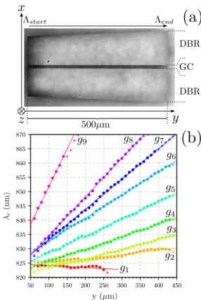
introduce a gradient of these dimensions along the grooves of the GC [9].
Figure 6 (a) shows the image of a fabricate CRIGF with a gradient where the dimensions are scaled linearly along the y-dimension (along the groove direction). The wavelength of the spectral peak reflected by such a CRIGF (Figure 6 (b)) depends on the position along the y-direction. By spatially scanning the position along this direction, one can tune the reflected wavelength, the slope of the tuning depending on the strength of the gradient applied to the dimensions (from no gradient in red to strongest gradient in purple).
The second approach relies on thermo-optic materials. By using a thin film of LiNbO3 for the waveguide (that is a
strongly non-linear, electro-optic and thermo-optic material), one can achieve tuning by altering the temperature of the substrate. Extremely recent results on thermally tuned CRIGFs working at telecom wavelengths [10][11] have demonstrated movement-free tuning over 2.4 nm for a temperature change of 60◦. In addition, preliminary observation of second harmonic generation enhancement by CRIGF in such material has been reported[12].
V. CONCLUSION
This contribution details the base principles of Guided Modes Resonant Filters (GMRFs) and Cavity Resonator In-tegrated Grating Filters (CRIGFs) and presents several appli-cations of CRIGFs to laser wavelength stabilization. Recent results on CRIGF wavelength tuning using spatial gradients or thermally active materials are also discussed.
ACKNOWLEDGMENT
F. Renaud acknowledges PhD grant from DGA/AID. Au-thors thankfully acknowledge the LAAS clean room team for technical support and technological expertise provided within the French RENATECH framework.
REFERENCES
[1] K. Kintaka et al., “Cavity-resonator-integrated guided-mode resonance filter for aperture miniaturization,” Opt. Express, vol. 20, no. 2, Jan. 2012, pp. 1444–1449.
Figure 6. CRIGF with a spatial gradient: (a) top-view of a graded CRIGF; (b) Local spectral reflectivity as a function of the strength of the dimension
gradient (from no gradient in red to strongest gradient in purple).
[2] X. Buet et al., “High angular tolerance and reflectivity with narrow bandwidth cavity-resonator-integrated guided-mode resonance filter,” Opt. Express, vol. 20, no. 8, Apr. 2012, pp. 9322–9327.
[3] N. Rassem, A.-L. Fehrembach, and E. Popov, “Waveguide mode in the box with an extraordinary flat dispersion curve,” J. Opt. Soc. Am. A, vol. 32, no. 3, Feb. 2015, pp. 420–430.
[4] X. Buet et al., “Wavelength-stabilised external-cavity laser diode using cavity resonator integrated guided mode filter,” Electronics Letters, vol. 48, no. 25, Dec. 2012, pp. 1619–1621.
[5] S. Aug´e et al., “Mid-infrared cavity resonator integrated grating filters,” Optics Express, vol. 26, no. 21, 2018, pp. 27 014–27 020.
[6] A.-L. Fehrembach et al., “Measurement and modeling of 2d hexagonal resonant-grating filter performance,” J. Opt. Soc. Am. A, vol. 27, no. 7, Jul. 2010, pp. 1535–1540.
[7] R. Laberdesque et al., “High-order modes in cavity-resonator-integrated guided-mode resonance filters (crigfs),” J. Opt. Soc. Am. A, vol. 32, no. 11, Nov. 2015, pp. 1973–1981.
[8] A. Monmayrant et al., “Cavity resonator integrated filter (CRIGF) based external cavity laser in a butterfly package,” in 2019 21st International Conference on Transparent Optical Networks (ICTON). IEEE, Jul. 2019.
[9] S. Aug´e, A. Monmayrant, S. Pelloquin, J. B. Doucet, and O. Gauthier-Lafaye, “Tunable graded cavity resonator integrated grating filters,” Optics Express, vol. 25, no. 11, May 2017, pp. 12 415–12 420. [10] S. Calvez, A. Monmayrant, and O. Gauthier-Lafaye,
“Lithium-niobate-based Cavity Resonator-Integrated Guided-mode Resonance Filters,” Jun. 2019, poster.
[11] S. Calvez, A. Monmayrant, and O. Gauthier-Lafaye, “Towards high-speed tuning Cavity Resonator-Integrated Guided-mode Resonance Filters,” in EOS Topical meeting on Diffractive Optics 2019, Jena, Germany, Sep. 2019.
[12] F. Renaud et al., “Second-harmonic-generation enhancement in cavity resonator integrated grating filters,” Opt. Lett., vol. 44, no. 21, Nov 2019, pp. 5198–5201.