Publisher’s version / Version de l'éditeur:
Journal of Thermal Insulation, 5, pp. 209-228, 1982-04
READ THESE TERMS AND CONDITIONS CAREFULLY BEFORE USING THIS WEBSITE. https://nrc-publications.canada.ca/eng/copyright
Vous avez des questions? Nous pouvons vous aider. Pour communiquer directement avec un auteur, consultez la première page de la revue dans laquelle son article a été publié afin de trouver ses coordonnées. Si vous n’arrivez pas à les repérer, communiquez avec nous à [email protected].
Questions? Contact the NRC Publications Archive team at
[email protected]. If you wish to email the authors directly, please see the first page of the publication for their contact information.
NRC Publications Archive
Archives des publications du CNRC
This publication could be one of several versions: author’s original, accepted manuscript or the publisher’s version. / La version de cette publication peut être l’une des suivantes : la version prépublication de l’auteur, la version acceptée du manuscrit ou la version de l’éditeur.
Access and use of this website and the material on it are subject to the Terms and Conditions set forth at
Insulating existing flat roofs : design and construction details
Burn, K. N.; Roux, R.
https://publications-cnrc.canada.ca/fra/droits
L’accès à ce site Web et l’utilisation de son contenu sont assujettis aux conditions présentées dans le site LISEZ CES CONDITIONS ATTENTIVEMENT AVANT D’UTILISER CE SITE WEB.
NRC Publications Record / Notice d'Archives des publications de CNRC: https://nrc-publications.canada.ca/eng/view/object/?id=c72af8c8-de69-4ae3-84dd-ec9c7d1ab1d4 https://publications-cnrc.canada.ca/fra/voir/objet/?id=c72af8c8-de69-4ae3-84dd-ec9c7d1ab1d4
TH1 N21d
National Research Conseil national
log4
1
+
Council Canada de recherche Canada c. 2t
INSULATING EXISTING FLAT ROOFS:I
DESIGN AND CONSTRUCTION DETAILSby Kenneth N. Burn and Richard Roux
ANALYZED Reprinted from
Journal of Thermal Insulation, Vol. 5 (April 1982)
p. 209 - 228
DBR Paper No. 1094 Division of Building Research
OTTAWA N R C
-
C I S T IBLDG. RES.
L I B R A R Y
83-
05-
I
e
B I B L I O T H Z Q U E
Rech. 0
:. i;> C N \ NRCC 21172Cette note traite des details de construction et de conception de l'isolation des toits des nouvelles constructions et de l'am6lioration de l'isolation thermique des bltiments existants. On insiste ici plus particulisrement sur les toits B BtancheitB rmlticouches B cause de leur usage trss rgpandu et des problemes particuliers dus au retrait de la membrane.
On analyse des p r o b l k s rencontr6e dans la pratique et on propose des solutions. Ces solutions peuvent ltre regroupks en principes qui peuvent s'appliquer en g6n6ral B la conception des details de toiture. On trouvera dans cette note des exemples d'adlioration de l'ieolation thermique de toits existants par application de ces princlpes.
Enfin, on trouvera une analyse de la fonction des joints utilis'es habituellement sur lea toits et des effets de l'isolation thermique sur leur conception.
Division of Building Research
National Research Council of Canada Ottawa, Ontario
Canada AND
Department of Civil Engineering Ecole Polytechnique
University of Montreal Montreal, Quebec Canada
INSULATING EXISTING FLAT ROOFS: DESIGN AND CONSTRUCTION DETAILS Manuscript received January 20, 1982
ABSTRACT: This paper deals with the design and construc-
tion of details pertaining to insulated roofs for new construc- tion and for thermal upgrading of existing ones. Emphasis is given to built-up roofs (BUR) because of their wide use and the particular problems associated with the tendency of the membrane to shrink.
Roof problems encountered in current practice are analyz- ed and practical solutions are suggested. Such solutions may be adopted as principles that can be applied, in general, to the design of practical roof details. Examples of the applica- tion of these principles to thermal upgrading of existing roofs are described.
Finally, the functions of the different types of joints usually found on roofs and the effects of insulation on their design are discussed.
INTRODUCTION
R
APID INCREASES IN PRICES for oil and other forms of energy since 1973 have dictated the search for more economical methods to heat and air condition buildings. One of the more effective ways of accomplish- Based on a paper presented at the Fourth International Conference on Thermal Insulation, Millbrae, California, January 18 to 20, 1982.I
1
Kenneth N. Burn and Richard Roux\
1 ing this is to insulate the building envelope. In general, the component most easily accessible for retrofitting is the roof, particularly if it is flat. Adding insulation, however, also entails altering the roofing to a greater or lesser extent and this frequently creates problems. I
Roofing consists of two main parts, the membrane covering the clear
.
areas of the roof surface and the flashings, which are special sheltering,
devices designed to protect the edges and penetrations of the mem- , brane. The functions and characteristics of the materials of both must:
be well understood before they can be dealt with intelligently. Proper ,application not only improves performance but also lengthens the ser- vice life of roofs. Poor flashing details are a major cause of roofing 1
i
failure.
The term, roof details, is understood to mean ways in which to con-
I
struct junctions between the roof and walls of a building at both parapets and penthouses. It also includes suitable arrangements for 'drainage and flashings around mechanical equipment supported on the r roof and around the service pipes and ducts that penetrate it. An- chorage of the membrane to the deck, especially where significant thicknesses of insulation are used, is another detail influencing the per- formance of the system that must be carefully considered. I
Probably more than 90 per cent of existing roofs and present roofing construction comprises bitumen-saturated felts overlapped and in- terlayered with on-site applied coatings of bitumen to form a water- ,
proof built-up roofing (BUR) system. Emphasis is given to this system because of its wide use and the particular problems associated with the
tendency of the membrane to shrink. I
A survey of roofing jobs shows that details are generally not given adequate consideration and are frequently left in the hands of those who have a limited understanding of their purpose. Too often they are copied directly from guidelines or suggested details in trade literature without thought or modification and without recognition that these details frequently represent only minimum requirements.
I
MEMBRANE BEHAVIOR
The asphalt built-up roofing membrane is a composite material that contracts when subjected to tensile stresses induced by a temperature I
drop or to moisture loss and may not be able to expand or return to its original position when these factors are relaxed or reversed. Such
Insulating Existing Flat Roofs: Design and construction Details
behavior may result in considerable net shrinkage in certain cases when the membrane is not sufficiently restrained.
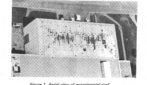
Figure I . Aerial view of experimental roof.
~ ? ~ - ~ e a r - o l d experimental roof (Figure 1) that is essentially a double- drained system was constructed as follows: concrete deck, bituminous membrane, rigid insulation and cap sheet. It is now in poor condition because the cap sheets have separated and wrinkled badly. The cap sheet is not a built-up roofing membrane but is made of the same basic materials and it is interesting to consider its behavior. When the cap sheets were mopped to the right insulation, overlaps were originally 3
in. laterally (75 mm), and 10 to 12 in. (250 to 300 mm) longitudinally.
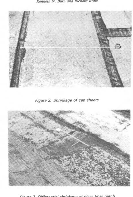
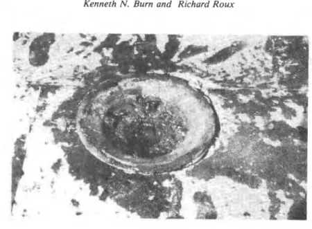
The original position of the edges and ends of each sheet where it
overlapped the sheet below can be seen from imprints on the adhesive used at the time of installation (Figure 2). Measurements indicate shrinkage in the order of 8 per cent laterally and 5 per cent longitudinal- ly. This has resulted in many openings between the sheets, exposing the insulation and necessitating repairs in certain locations. Where a glass fiber mesh was mopped on top of open joints further shrinkage was prevented in the vicinity of the path, but the unrestrained parts of the sheet continued to shrink. In some places this amounted to an addi-
I
Kenneth N. Burn and Richard ROUX
A ' > A +
' " . * i .
t
Figure 2. Shrinkage of cap sheets.
I
I
Figure 3. Differential shrinkage at glass fiber patch. 1
I Edge restraint is thus necessary if shrinkage is to be prevented. Poor I
bonding or too much asphalt between the felts may permit shrinkage. It
]
should be stressed that the cap sheets shrank but never expanded again to their original length.21 2
Insulating Existing Flat Roofs: Design and Construction Details
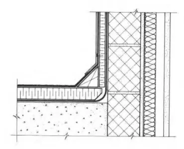
Figure 4. Section at parapet as installed.
Figure 5. Shrinkage of cap sheet resulting in lifting from insulation.
At the parapet, the cap sheet was nailed beneath the metal
counterflashing after being mopped over the cant strip (Figure 4).
Shrinkage of the cap sheet resulted in its separating and lifting from the
Kenneth N. Burn and Richard R o w
sheets were not able to withstand this tension while others failed when stepped on. If the sheets had been held in place, as they would have been if fastened to a nailing strip, lifting from the insulation and failure in tension in this area would have been prevented. In fact, the mem- brane lifted under tension and rain washed the cap sheet protection away. Ultra-violet radiation and water contributed to the end result.
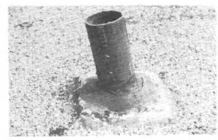
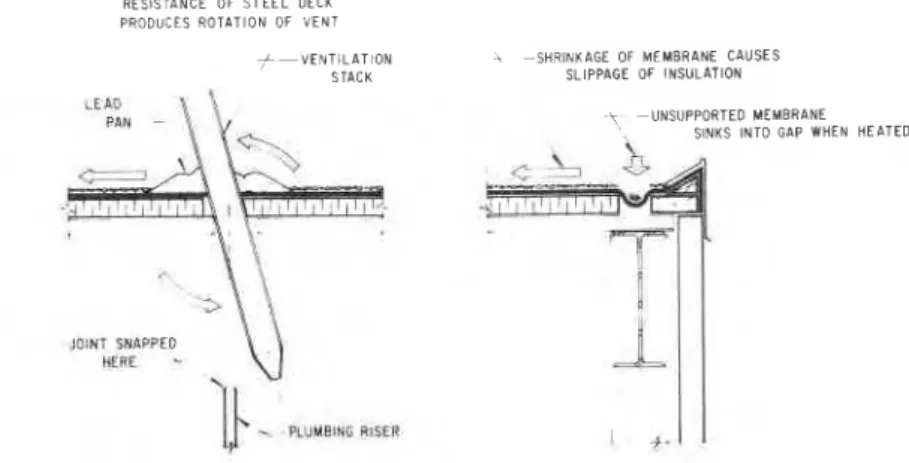
Evidence of shrinkage and the forces produced by a conventional membrane are shown by sloping vent pipes that were set solidly in lead pans (Figure 6). Removal of the dropped ceiling beneath revealed that the connection of the plumbing riser and vent pipe had broken and that the ends were 6 in. (150 mm) apart (Figure 7). In shrinking, the mem- brane pulled the vent pipe against the edge of the opening in the steel deck and forced the pipe to rotate. The membrane also dragged the in- sulation, closing its joints and causing a 4-in. (100 mm) gap to develop at the eave between the end board and the nailing strip. The unsup- ported membrane sank into the space when temperatures were high enough to cause plastic flow. These observations are based on a test cut shown in Figure 8. On the same roof, insulation was forced against a drain on one side, leaving a space on the opposide side (Figure 9).
Figure 6. Sloping vent pipe set in lead pan.
Insulating Existing Flat Roofs: Design and Construction Details
SHRINKAGE OF MEMBRANE AND RESISTANCE OF S T E E L DECK PRODUCES ROTATION OF VENT
f-VENTILATION i S H R I N K A G E OF MEMBRANE CAUSES
STACK SLIPPAGE OF INSULATION
\ U N S U P P O R T E D MEMBRANE SINKS INTO GAP WHEN HEATED
,- a
1UINf SNAPPED
hfHE -.
-
PLUUEIMG WSERFigure 7. Section through roof showing effects of membrane shrinkage on vent pipe and insulation.
Figure 8. Test cut at eave.
In both cases lack of adhesion between the insulation and the steel deck contributed to the failures. The membrane, well-bonded to the in- sulation, would probably have stayed in place if the insulation had been properly attached to the steel deck. It is difficult, however, to achieve
Kenneth N. Burn and Richard Roux
Figure 9. Effect of membrane shrinkage on insulation at roof drain.
good attachment of insulation materials to steel decks using adhesives. Mechanical fasteners, which provide more positive resistance to slip- page at this interface, are available.
Other evidence shows that shrinkage forces in the membrane are not negligible. This is graphically illustrated in an example in which a mem- brane anchored to the parapet developed sufficient force to cause ben-
ding failure of the brick wall four courses below (Figure 10). The forces
involved, though appreciable, are fortunately only a fraction of the ten- sile strength of a four-ply roofing membrane and should not in themselves cause splitting of the membrane. Weather conditions cause these forces to be relaxed periodically, as shown by the shrinking of the membrane into the gap at the roof perimeter, already described (Figure
8).
These observations and the property of a built-up roofing membrane to shrink leads to the conclusion that the membrane must be securely attached so that the forces produced by weathering can be transmitted to and resisted by the structure. This can be accomplished by the use of fasteners in the clear areas of the roof surface and by anchoring the membrane in its own plane to suitable blocking where the membrane ends.
Insulating Existing Flat Roofs: Design and Construction Details
MOVEMENT OF MEMBRANE CAUSED
7
BY SHRINKAGE FORCES-TOP 4 COURSES OF BRICK
AND WOOD BLOCKING P U L L E D
INWARD BY CONTRACTING
MEMBRANE
Figure 10. Force of shrinking membrane resulting in bending failure of brick veneer.
prevent the occurrence of ridges, blisters and other forms of membrane failure. There are many unfavorable weather conditions to be contend- ed with and poor practices to be avoided if a good membrane is to be achieved. Better quality control appears to be necessary.
DRAINAGE
Water is the arch enemy of all building materials and roofing mem- branes are no exception. It is important to remove water as soon as possible by suitable drainage. Unfortunately, many existing flat roofs were constructed without deliberate slopes, and drains are frequently located in the wrong areas. For convenience, they are often placed near columns, which remain the highest points when structural deflections develop, with the result that ponding occurs and large amounts of water remain until they either evaporate or seep through the roof. In retrofitting it is possible to tell where the low spots are by surveying a roof after a rainfall; the drains can then be moved to these locations if the performance of the roof is to be improved and its service life lengthened.
If there are practical reasons why the drains cannot be moved, con- sideration should be given to building in slopes by adding lightweight
Kenneth N. Burn and Richard Roux
fill, which will entail a structural investigation, or by installing tapered insulation boards.
FLASHINGS
A flashing is a sheltering device used to prevent water from entering
the interior of building elements such as walls and roofs at openings for mechanical equipment, skylights and other services. Its function is to intercept and deflect rain as quickly as possible onto the membrane.
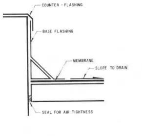
Flashings must be designed to take care of the forces that cause rain penetration, including: the kinetic energy of wind-driven rain, capillari- ty, gravity, and air pressure differences resulting primarily from wind action. In practical terms, and in present practice, flashing is essentially a two-component system made up of a base flashing, which is a pro- longation of the membrane, and an umbrella or counterflashing, which covers the edge of the base flashing and the top of the wall or parapet.
COUNTER - F L A S H I N G
7
r B A S E FLASHINGMEMBRANE
,
,
70 bRAINI S E A L FOR AIR TIGHTNESS
Figure 7 7. Schematic of components at edge of roof.
Base flashings (Figure 11) are usually flexible, often of the same ma-
terial as the roofing membrane or some waterproof material that iscom-
patible with it. They are adhered to theedge of the membrane and turned
Insulating Existing Flat Roofs: Design and Construction Details
Counter flashings, usually of sheet metal, should be sufficiently rigid and adequately attached to the structure to resist wind action, and they should be designed so that they can be fastened together without ex- posing nail heads and holes to the weather.
Depending on the type of construction, vertical differential movements may occur between the wall and the roof deck, so that base flashings and counterflashings should generally not be attached. If they are, they can be torn apart and water will enter the roof.
A gravel stop is an exception. Metal counterflashings are normally re- quired to be securely attached to the edge of the membrane at the horizontal leg, with felts mopped over. Experience shows that gravel stops generally perform well; this form of construction requires that the membrane be well nailed at the perimeter, preventing it from shrinking. The main disadvantage of this type of roof edging is that it has little or no capacity to hold water if the drains become plugged, and water spills or is blown onto the walls in high winds.
Caulking materials have been used in roofs, usually in an attempt to stop leakage at counterflashings. All caulking materials deteriorate, however, when exposed to weather, and experience shows that they are least durable on roofs because of the extreme conditions en- countered there. Caulking deterioration frequently results in roofing failure. Caulking of joints at roof penetrations and flashings is, therefore, of limited value.
FREE ACCESS TO ROOF MEMBRANE
Some roofs support many types of equipment. Access to the mem- brane for roof maintenance or membrane replacement should be con- sidered at the design stage. Equipment can be located on piers so that the roofer will be able to reach the membrane easily. Lack of access to the membrane beneath equipment causes particular problems in retrofitting and sometimes the only solution is to build curbs and pro- vide a shelter.
DESIGN PRINCIPLES
A review of the foregoing discussion indicates a few points that may be considered as design principles. In summary they are:
Kenneth N. Burn and Richard Roux
-that the membrane be adequately bonded or fastened to the struc- ture in the clear areas of the roof surface and anchored in its plane at the perimeter to prevent shrinkage and lifting by wind action, -that the roof be properly drained, with positive slopes,
-that flashings be designed to control rain penetration without the use of caulked joints,
-that provision be made for sufficient clearance beneath roof- supported mechanical equipment for proper maintenance.
ROOFING JOINTS
Three types of joints have been used on built-up roofs: 1) the roof expansion joint,
2) the roof area divider, and
3) one referred to as a "membrane control" joint.
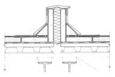
The roof expansion joint should consist of two curbs constructed on either side of a separation in the roof deck between which differential movements are expected to occur (Figure 12). This detail allows base flashings to be turned up well above the roof level, but to ensure water tightness against high water levels it is sealed with a flexible membrane at the top of the curbs. Continuity of the vapor retarder across the opening is ensured by another flexible membrane capable of withstan- ding the anticipated movements without failing, and the space between the curbs is filled with a flexible insulation to prevent condensation at the vapor retarder.
Shrinkage forces in the membrane could, of course, pull the curbs apart and eventually cause failure of the joint. To prevent this the mem- brane must be securely anchored to the deck on both sides. This is achieved by bolting the nailing blocks that support the curbs to the deck and nailing the edge of the membrane in its own plane, i.e., without turning it up, to the top of the nailing blocks. The cant strips are then secured in place and the base flashings mopped to the top of the membrane and up the curbs. A counter-flashing protects the whole system against ultra-violet radiation and mechanical damage.
The detail for a roof area divider is essentially the same as that for the
expansion joint except that it is placed where no differential movement
of the deck is anticipated (Figure 13). It is not necessary, therefore, to have G o separate curbs. Again, the vapor retarder is continued from one area to the other and the membrane is prevented from shrinking
Insulating Existing Flat Roofs: Design and Construction Details
Figure 12. Construction of an expansion joint.
Figure 13. Construction of an area divider.
by securing it, in its own plane, to the supporting nailing blockthat is anchored to the deck. The bituminous base-flashings are then mopped up and over the cant strips and curb. The principle of dividing roof areas to prevent stress concentrations is illustrated in Figure 14. It
Kenneth N. Burn and Richard Roux
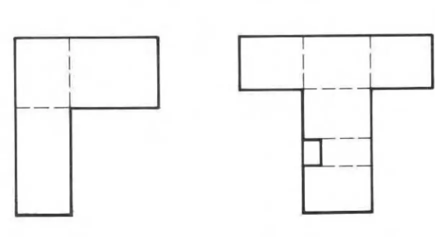
Figure 14. Dividing roof areas to avoid reentrant corners.
Figure 15. Membrane control joint.
consists basically of dividing the roof into square or rectangular areas ;
and avoiding shapes that produce re-entrant corners where most split-
ting failures occur. They can also be used as construction joints to limit
1
the area the roofing team can complete in one day, including gravelling, I I
to minimize failures that result from overnight weather changes.
I
I
Insulating Exkting Flat Roofs: Design and Construction Details
Membrane control joints are constructed with the intention of reliev-
ing tension stresses in the membrane by allowing it to move (Figure
15). They are usually constructed by cutting through the membrane
after it has been installed and then supporting, over back-to-back fiber
cants, a sheet of flexible material which is sealed on either side to the main roof membrane.
This approach is based upon the incorrect assumption that BUR membranes behave elastically. But the membrane has a tendency to
shrink and, unless it is restrained, movements will occur that will, in this
case, eventually pull the joint apart allowing water to enter the roof. If, on the original roof, splitting of the membrane has been a problem, this type of joint will not provide a solution. The situation should be careful- ly examined and consideration given to using either a "roof area
divider" if it appears that stress concentrations have developed or an
"expansion join^" if' differential movements in the deck are the cause.
THERMAL UPGRADING OF EXISTING FLAT ROOFS Generally, the easiest and cheapest way to insulate an existing flat roof is by placing insulation on top of the existing membrane. This leads to consideration of two main systems: the protected membrane system and the double drained system.
When the protected membrane system is considered, a check must be made to ensure that the structure will perform adequately under the additional dead load of the ballast. Recently, a lightweight mesh has been introduced that allows reduction of ballast. The mesh is stretched over the top of the insulation and, in combination with minimal ballast, prevents blow-off and allows the insulation boards to float in unison during temporary flooding. Another possible solution to the ballast pro- blem might lie in the use of mechanical fasteners. As well as being pro- tected by insulation against mechanical damage and that resulting from ultra-violet radiation, the protected membrane system has the advan- tage that the membrane is placed in a more stable thermal environment, with a greatly reduced tendency to shrink.
The double drained system might be considered where the structural capacity of the roof is inadequate for the addition of ballast necessary for the protected membrane system. Insulation may be laid directly on the roof with or without removing the existing gravel and a new mem-
brane installed above it, as on a conventional roof. The old membrane
Kenneth N. Burn and Richard Roux
drainage in the event of failure in the new membrane. Naturally, if the
existing membrane is in an advanced state of deterioration, it may be
necessary to remove it entirely and build either a conventional insulated
system or a new protected membrane system.
In upgrading a roof with insulation t o improve
Its
thermal perfor-mance the opportunity should also be taken to improve the air tightness of the wall-roof junction. Air leakage at the roof perimeter is frequently
a major factor of energy losses.
APPLICATION
To illustrate how these principles may be used, consider the arrange-
ment shown in Figure 16, a wall-roof junction that is to be thermally
upgraded. This is a steel structure with a concrete block exterior wall. The existing membrane is adhered to fiberboard resting on a fluted steel deck.
Wth the membrane in good condition, the gravel can be scraped off
and repairs made where necessary. The system may be converted as shown in Figure 17. Examination of the existing roof showed that ver- tical differential movements had taken place at the wall-roof junction.
The new details must take this into consideration and must accom-
modate the vertical movements at the eaves. The membrane is cut at
the perimeter of the steel deck and the flashing removed. A flexible
continuous membrane extends from the lower existing membrane to which it is mopped, bridges the gap between the deck and the wall, covers the head of the wall, and is integrated with the air vapor barrier
on
the
face of the block wall. This provides for air tightness of the wall-roof junction.
A new nailing strip wide enough to span one trough of the fluted
deck and of the same thickness as the insulation is secured to the steel
deck. The new top membrane, wood cant strip and curb are nailed to it.
The insulation is then laid and the new membrane is constructed and secured in its own plane at its perimeter. The base flashing is made con- tinuous with the new roof membrane and with the flexible membrane laid over the top of the wall. Experience shows that this works well as long as existing slopes are adequate and double drains are installed.
This detail does have a few drawbacks. The wide nailing strip an- I
chored to the deck is a thermal bridge and the low profile of the cant strip can lead to water leakage into the wall insulation in the event of
Insulating Existing Flat Roofs: Design and Construction Details
Figure 16. Existing wall-roof junction.
Figure 17. Possible upgrading No. 1.
accidental roof flooding and overtopping. In addition, a wide area of the counter flashing sheds water onto the wall and this could cause staining of the exterior wall finish. Failure of the joints between sections of unsupported flashing could also lead to water leakage into the wall
Kenneth N. Bum and Richard Roux -\ .
Figure 18. Possible upgrading No. 2, with an enlarged parapet.
Figure 19. Possible upgrading No. 3, using the protected membrane system. insulation. These problems could be overcome with a higher built-up parapet, which would prevent overtopping and would drain water to the roof, and by widening the parapet for more insulation, as shown in Figure 18. A rubberized membrane is used as a cover for the plywood
Insulating Existing Flat Roofs: Design and Construction Details
parapet and is continuous with the base flashing. In the event that a structural check indicates it is feasible, the protected membrane system could be used as shown in Figure 19. Many other arrangements are possible and undoubtedly those shown could be improved. They are in- tended simply to indicate how the principles outlined earlier might be implemented.
Of the three solutions, the protected membrane system is probably the cheapest, the simplest to construct, and technically the most sound. The choice of insulation for this solution, however, is rather limited and may be considered by some as a disadvantage.
SUMMARY
Basically, there are two methods that may be used in adding insula- tion to upgrade the thermal resistance of a roof. The protected mem- brane system, which can only be used if the structure can safely carry the extra load of ballast, greatly reduces the tendency for the built-up roofing membrane to shrink. With the double-drained system, which adds very little load to the roof, the membrane is exposed to ambient conditions and should be adequately secured at the perimeter to pre- vent shrinkage.
In retrofitting, there is the advantage of knowing what is wrong with the existing roof, where it is ponding, and where flashings and mem- brane have failed. This provides basic information on the particular re- quirements that should be considered in preparing details for upgrading.
ACKNOWLEDGEMENT
The authors gratefully acknowledge the assistance and encourage- ment of their colleagues at the Division of Building Research.
This paper is a contribution from the Division of Building Research, National Research Council of Canada, and is published with the ap- proval of the Director of the Division.
BIBLIOGRAPHY
1. Baker, M.C., Flashings for Membrane Roofing, National Research Council of Canada, Division of Building Research, Canadian Building Digest 69,
Sept. 1965.
2. Baker, M.C. Roofs - Design, Application and Maintenance, Multiscience Publications Ltd., Montreal, 1980.
Kenneth N. Bum and Richard Roux
3. Garden, G.K., Rain Penetration and Its Control, National Research Council of Canada, Division of Building Research, Canadian Building Digest 40, April 1963.
4. Handegord, G.O., and M.C. Baker, Application of Roof Design Principles, National Research Council of Canada, Division of Building Research, Cana- dian Building Digest 99, March 1968.
5. Jones, P.M., Some Engineering Properties of Built-up Roofing, American Society for Testing and Materials, STP 347, 1963, p. 70-81.
6. Solvason, K.R. and G.O. Handegord, Ridging, Shrinkage and Splitting of Built-up Roofing Membranes, National Research Council of Canada, Divi- sion of Building Research, Building Research Note 112, June 1976. 7. Turenne, R.G., Joints in Conventional Bituminous Roofing Systems, Na-
tional Research Council of Canada, Division of Building Research, Cana- dian Building Digest 202, Jan. 1979.
8. Turenne, R.G., Shrinkage of Bituminous Roofing Membranes, National Research Council of Canada, Division of Building Research, Canadian Building Digest 181, July 1976.
Thie publication is being dietributed by the Division of Building R e e e a r c h of the National R e r e a r c h Council of Canada. I t rhould not be reproduced in whole o r in p a r t without permieeion of the original publirher. The Di- vieion would be glad to be of a e r i r t a n c e in obtaining such permieeion,
Publications of the Divieion may be obtained by m a i l - ing the a p p r o p r i a t e r e m i t t a n c e (a Bank, Exprere, o r P o e t Office Money Order, o r a cheque, m a d e payable to the Receiver General of Canada, c r e d i t NRC) to the National Reeearch Council of Canada, Ottawa. K1A OR6. Stamps a r e not acceptable.
A l i s t of a l l publications of the Divieion is available and may be obtained f r o m the Publicationr Section, Divieion of Building Reeearch, National R e e e a r c h Council of Canada, Ottawa. KIA OR6.