Chaotic Vibration in Machine Systems and
Its Implications for Design
by
Pengyun GuB.S., Shanghai Jiao Tong University, 1982 M.S., Shanghai Jiao Tong University, 1984
Submitted to the
Department of Mechanical Engineering
in partial fulfillment of the requirements for the degree of Doctor of Philosophy
at the
Massachusetts Institute of Technology June 1994
© 1994 Massachusetts Institute of Technology All rights reserved
Signature of Author ...
Department of Mechanical Engineering June 1, 1994
Certified by
/- Prc(sor Steven Dubowsky
Thesis Supervisor
Accepted by
Professor Ain A. Sonin Chairman, De par4metal Graduate Committee
.,,
; -lVN
-.i
I
L(OT 24
1994
Chaotic Vibration in Machine Systems and Its Implications for Design by
Pengyun Gu
Submitted to the Department of Mechanical Engineering On June 1, 1994, in partial fulfillment of the requirements
for the degree of Doctor of Philosophy Abstract
Accurate prediction of machine performance is a key to the design of high performance machines. Due to the existence of clearance connections and component flexibility, the dynamic behavior of machine systems exhibits sensitivities to small variations of system parameters. These sensitivities limit the usefulness of predictions from computer-based simulations for design. Certain sensitivities are associated with chaotic behavior of the systems. This thesis investigates the design implications of chaotic behavior in machine systems with clearance connections and component flexibility. It also proposes a design methodology to most effectively use the predictions of machine models at the design stage.
The dynamic behaviors of two systems, called the Impact Beam System and the Spatial Slider Crank, are investigated. The existence of chaotic vibrations in these two systems is confirmed both numerically and experimentally. The dynamic responses of these systems can be classified into three characteristic types. These classifications are useful guidelines for design.
While Type I Response is well-behaved, Type II and Type III Responses are sensitive to small variations of the system parameters, presenting important design problems. The dynamic behavior of such machine systems could be quite different from model-based predictions due to these sensitivities. In particular, the periodicity of the Type II Response may lead designers to overlook the sensitivities. Design guidelines are developed for classifying these three types of responses and for evaluating the fatigue life and the reliability of machine systems at the design stage.
Thesis Supervisor: Dr. Steven Dubowsky
Acknowledgments
I would like to thank my thesis advisor, Professor Steven Dubowsky, for his guidance, inspiration, and financial support throughout this work. His depth of knowledge and keen insights into the subject have been my sure guide in this research. His enthusiasm for exploring new concepts and new
approaches will always be a positive influence on my professional career. I wish to express my gratitude to Professors Stephen Crandall and Steve Strogatz for serving as members of my thesis committee and for their valuable critical comments at various stages of the research. Professor Crandall, listening to your lectures during AV Lab lunch meetings has been a very enjoyable learning experience. I wish I could take more courses taught by you. Professor Strogatz, thank you for teaching me chaos in your class. I really like your teaching style.
I wish to express my thanks to Dr. Ming-Kai Tse for guidance and encouragement as well as financial support for my early years at MIT.
I am very grateful to Professor Richard Lyon for teaching me Statistical Energy Analysis and many useful discussions on noise and vibration issues as well as for helping me in my career planning.
I thank my Chinese friends at MIT: Drs. Zhong Cai, Fuquan Gao, Xiaojun Liu, Li Lin, Jie Ren, Hong Tian and Youhong Gong. I would like to thank Professor Zhao Chunsheng and his family for their friendship. Professor Zhao, thank you for beautiful flowers and for taking many memorable pictures after my thesis defense. Good luck for your research in China.
I would like to thank Fred Cot6 for his help for my experimental setup. With his assistance, I could have my work done and keep my ten fingers well. I would like to express my thanks to my colleagues, both past and present, in Dr. D's group. All of you have created an enjoyable, yet productive, atmosphere. I would to says: thanks for many jokes and helpful hands. Thanks to Jeff Cole, Tom Corrigan, Dr. Dinos Mavroidis, Nate Rutman, Craig Sunada, Michele Tesciuba, Richard Wang, Dr. Kazuya Yoshida for many useful suggestions when I prepared my thesis defense. In particularly, to Dinos for many suggestions and discussions since you joined this group.
I would like to thank members of "Machine Dynamics Group": Dr. Joe Deck, Erin O'Connell, and Dr. Charles Oppenheimer. Charles gave many suggestions for my research. We had many discussions on SEA. Thank you for recommending me to serve as AV Lab manager. I learned a lot from this job. Joe has helped me in many ways. He is a very knowledgeable colleague. From the day I walked into room 3-443, my "one question strategy" for Joe has been working very well. His patience and generosity have made me very comfortable to work with him for many years. He taught me how to run his program which has been used extensively in this research. He gave me many constructive suggestions for my research. I remember many, many discussions we had. I am very grateful to Joe for his critical reading on both the English and technical aspects of my thesis. Thank you Joe, I wish you good luck in your life. For Uwe Miiller, although you were not a member of this sub-group, I appreciate your help for my experiments. I am glad you were MIT when I served lunch for the group. Good luck in Germany. I will see you there.
Thanks to Kate Melvin for providing technical support and helping my English.
Thanks to Laureen Luszcz for her assistance since she came back to this group.
I would like to thank other professors of the Acoustics & Vibration/Machine Dynamics Laboratory: Triantaphyllos Akylas, Patrick Leehey, Frank Feng. They listened to my presentations in Lab lunch meetings and made suggestions. Thanks to Professor Frank Feng for friendship and for coming to my thesis defense. I wish you good luck at MIT. I thank student members of the Lab: Djamil Boulahbal, Dr. Jangbom Chai, John •hi, Sophie Debost, Hua He, Dr. Kay Herbert, Chris Lerch, Dr. Dan McCarthy, Roni Shlomi, In-Soo Suh for their cooperation and support when I wcrked as lab manager.
I thank Mary Toscano and Laurie McLaughlin for their help during my tenure as AV lab manager.
I thank Leslie Regan for effective administration and her help whenever I walked into her office.
Thanks to my cousin, Shengming Lin, and his family, for their help to my family.
I am especially grateful to my uncle and aunt, Institute Professor and Mrs. C. C. Lin for their generosity, concern, encouragement and guidance. Uncle's advice on "Why, What and How" has a great influence on my research and my future career. Aunt has helped our family whenever we needed.
I would like to thank my "family-in-law" for their support and for having faith that I would one day be able to provide for my wife. Thanks to my parents-in -law for taking care of my son and for everything they have done for me and my family.
My mother and father deserve a great of thanks for their love, encouragement, and support through my long education. Mom and dad, thank you for firm supports whenever I pursue my goals. Your expectation has been a continuous source of motivation. You should be proud of my achievements. To my young sister, thank you for your love and encouragement. I wish you good luck in your pursuits.
My son Steve has helped me in many ways he is still too young to understand. Steve, thank you to make my life more enjoyable.
Finally, I would like to thank my lovely wife, Dr. Hui Xie, who has sustained me throughout this many years at MIT. Hui, thank you for enduring so long and having great inspiration and faith. You have provided all the support and encouragement to keep me going when it all seemed hopeless. In many ways, this accomplishment is yours as well as mine. Without your love, talent and support in times of struggle, this dissertation would not exist today. Now, I am done. Let us enjoy our new, wonderful life.
The support of this research by the National Science Foundation under grant number MSS-9023487 is greatly appreciated.
Table of Contents A b stract ... 3 Acknowledgments...7 Table of Contents ... ... 11 List of Figures...15 List of T ables... ... 19 1 Introduction ... 21 1.1 M otivation ... ... 21
1.2 Background and Literature Review...22
1.2.1 Modeling Clearance Connections and Component Flexibility ... 22
1.2.2 Chaotic Behavior of Simple Impact Oscillators ... 23
1.2.3 Chaotic Behavior of Mechanisms ... 25
1.3 Objective and Approach... ... ... 27
1.4 Contributions of the Research ... 28
1.5 Thesis Overview...29
2 Basic Tools and Concepts ... 32
2.1 Introduction ... ... 32
2.2 Dynamic Modeling of Machine Systems ... 32
2.2.1 The Dynamic modeling Technique... 32
2.2.2 Connection Models ... 35
2.3 Basic Concepts of Chaotic Dynamics... ... 37
2.3.1 Diagnostics of Chaotic Vibrations ... 37
2.3.2 Routes to Chaos... 40
3 Study of an Impact Beam System ... 42
3.1 Introduction ... 42
3.2 The System ... 42
3.3 Analytical Model of the Impact Beam System ... 47
3.4 Simulations of Dynamic Responses of the System...48
3.5 Effects of System Parameters on the Dynamic Response...54
3.5.1 The Effect of Clearance and Excitation Frequency ... 55
3.5.2 The Effect of Beam Dimensional Variation...61
3.5.3 The Effect of Damping ... .... 63
3.7 Comparison of Experimental and Numerical Results...71
3.8 Summary ... 76
4 Study of a Spatial Slider Crank Mechanism ... ... 78
4.1 Introduction ... 78
4.2 The Spatial Slider Crank Mechanism ... 78
4.3 Analytical Model of the Spatial Slider Crank Mechanism...84
4.3.1 Model of the Mechanism ... 84
4.3.2 Models of Clearance Connections ... 85
4.4 Simulations of Dynamic Responses of the Mechanism...87
4.4.1 Impact Responses in the Clearance Ball Joint ... 88
4.4.2 Impact Responses in the Clearance Slider Joint...93
4.5 Effects of System Parameters on the Dynamic Response...97
4.5.1 The Effect of Clearance and Crank Speed ... 99
4.5.2 The Effect of Link Dimensional Variation...101
4.5.3 The Effect of Friction in Slider Joint...102
4.5.4 The Effect of Contact Damping ... 103
4.5.5 The Effect of Component Flexibility ... ... 105
4.6 Experimental Responses of the Mechanism ... 108
4.7 Comparison of Experimental and Numerical Results ... 117
4.8 Summary... ... 120
5 Design Methodology for Machine Systems with Chaotic Vibration ... 122
5.1 Introduction ... 122
5.2 Methods for Testing Chaotic Vibration ... 123
5.2.1 Two-Step Test Method...123
5.2.2 Matrix Update Test Method...124
5.2.3 Discussion...129
5.3 Predictive Criteria for Chaotic Vibration ... ... 132
5.3.1 Predictive Criteria ... 132
5.3.2 Precursors of Chaotic Behavior ... 135
5.4 Design for Machines with Chaotic Response ... 137
5.4.1 Characteristics of Impact Force...138
5.4.2 Estimation of Fatigue Life and Reliability...145
5.4.3 Calculation of Statistical Parameters ... 151
5.5 The Classification of Type I, Type II, and Type III Responses...153
5.5.1 The Approach...153
5.6 The Proposed Design Methodology... ... 158
5.7 Sum m ary ... 163
6 C onclusions ... ... 164
6.1 C onclusions...164
List of Figures
Figure 3.1 Schematic diagram of the Impact Beam System ... 44
Figure 3.2 Experimental setup of the Impact Beam System ... 44
Figure 3.3 IBS adjustable clearance joint and contact sensor...45
Figure 3.4 Schematic diagram of experimental measurement ... 46
Figure 3.5 Dynamic model of the Impact Beam System ... 47
Figure 3.6 A periodic response of the IBS ... ... 50
Figure 3.7 A chaotic response of the IBS ... ... 52
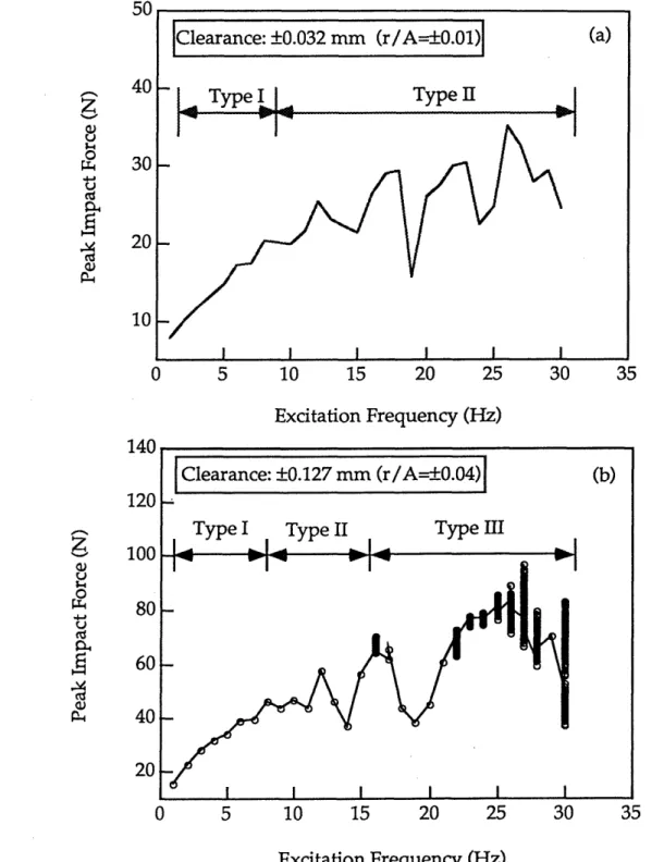
Figure 3.8 Peak impact force as a function of the excitation frequency...56
Figure 3.9 Response nature of the IBS in Excitation frequency-Clearance space ... ... 58
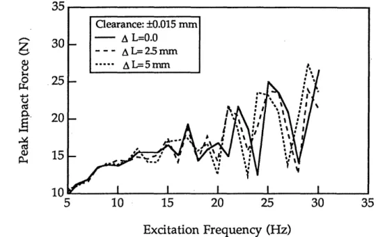
Figure 3.10 Peak impact force as a function of excitation frequency for different beam lengths ... 60
Figure 3.11 Peak impact force as a function of frequency ratio for different beam lengths ... ... 61
Figure 3.12 Peak impact force as a function of beam length variation ... 62
Figure 3.13 Peak impact force as a function of structural damping ratio...63
Figure 3.14 An experimental result. A periodic response of the IBS...65
Figure 3.15 An experimental result. A chaotic response of the IBS...67
Figure 3.16 Experimental results. Peak impact force as a function of excitation frequency...70
Figure 3.17 Comparison between experimental and numerical results...72
Figure 3.18 Comparison of experimental and numerical results. The nature of the response in Excitation frequency-Clearance space ... 76
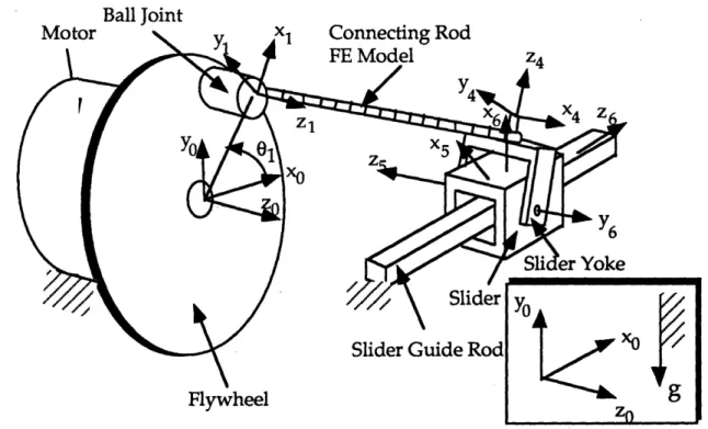
Figure 4.1 Schematic diagram of a spatial slider crank mechanism ... 79
Figure 4.2 Experimental spatial slider crank mechanism ... 81
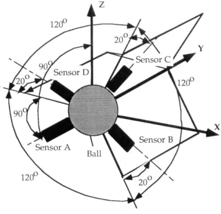
Figure 4.3 Instrumented, adjustable clearance ball joint...82
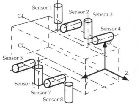
Figure 4.4 Instrumented, adjustable clearance slider joint ... 83
Figure 4.5 Numerical model of the SSC ... 84
Figure 4.6 Spherical Clearance Connection model...86
Figure 4.7 Contact force in the ball joint...88
Figure 4.8 Peak impact force as a function of crank speed ... 89
Figure 4.9 The nature of the response of the SSC in Crank speed-Clearance space... 90
Figure 4.11 Contact force in instrumented clearance slider joint...93
Figure 4.12 Slider vibration ... ... ... 95
Figure 4.13 Peak impact force as a function of crank speed in the slider joint... ... 97
Figure 4.14 Peak impact force as a function of crank speed in the slider join t...98
Figure 4.15 The nature of the responses of the SSC in Crank speed-Clearance space for the slider joint ... 101
Figure 4.16 Peak impact force in the slider joint as a function of length variation of the connecting rod ... ... 102
Figure 4.17 Effect of friction in the slider joint on the dynamic behavior... ... 104
Figure 4.18 Peak impact force as a function of crank speed. Showing superharmonic resonant responses...106
Figure 4.19 Schematic diagram of the SSC measurement ... 108
Figure 4.20 Measured contact force in the instrumented ball joint ... 110
Figure 4.21 Measured contact force in the instrumented slider joint...111
Figure 4.22 Measured peak impact force in the slider joint as a function of crank speed. ... ... 113
Figure 4.23 An experimental result. Slider vibration ... 114
Figure 4.24 Experimental results. Peak impact force as a function of the crank speed for different beam lengths...116
Figure 4.25 Comparison between experimental and numerical results...119
Figure 5.1 Peak impact force as a function of operating cycle. A periodic response. ... 127
Figure 5.2 Peak impact force as a function of operating cycle. A chaotic response . ... 128
Figure 5.3 Mean and one-standard deviation of a chaotic response as functions of the matrix update interval. ... 129
Figure 5.4 (a) A transient chaotic response. (b) A chaotic response ... 131
Figure 5.5 Flow chart of testing chaotic vibrations ... 133
Figure 5.6 Time histories of impact force ... 136
Figure 5.7 Simulation results of the IBS. Histograms of peak impact forces ... ... 140
Figure 5.8 Experimental results. Histograms of peak impact forces in the slider joint. ... ... 141
Figure 5.9 A simulation of the SSC. Histogram of peak impact forces
in the slider joint. ... ... 142 Figure 5.10 Peak Impact Diagrams of impact forces in the ball joint ... 143 Figure 5.11 Peak Impact Diagram of impact forces in the slider joint ... 144 Figure 5.12 Estimated relative fatigue life of the slider joint as a
function of crank speed...48 Figure 5.13 Peak Impact Diagrams of impact forces in the slider joint...152 Figure 5.14 Statistical parameters of the peak impact force as functions
of the number of operating cycle ... 154 Figure 5.15 Flow chart of the proposed design methodology...161
i9raxarra~·---~·~l·---·r~-r~--List of Tables
3.1 The first natural frequencies of the beam for different lengths ... 59 4.1 Hartenberg-Denavit parameters and link types of the SSC ... 85
Chapter 1 Introduction
Chapter 1
Introduction
This chapter explains the motivation for this research, reviews previous work in the related areas, highlights the contributions of the thesis, and finally, outlines the organization of this thesis.
1.1 Motivation
Over the decades, many analytical design models have been developed to predict the dynamic performance of machines with non-ideal characteristics such as clearance connections and component flexibility [3-10,12-14,25,27,28,34,40,41,57-59]. The effects of such non-ideal characteristics often degrade a machine's dynamic performance by causing impacts, vibration and noise, component fatigue, and poor precision. These developed models have focused on predicting this dynamic behavior.
Recently, it has been found that the dynamic responses of machine systems with clearance connections could exhibit both a large variation and high sensitivity to small parameter changes and operating conditions [3,4]. The findings have suggested that there are limitations on predictions of the responses based on machine models for design analysis, due to the sensitivity of the responses to small variations of machine parameters. Since every real engineering design, when manufactured and used, is subject to variations in its parameters, such as in its component dimensions and material properties, the real dynamic behavior of a machine could be quite different from the behavior predicted using an analytical modeling method.
The sensitivity of the dynamic behavior in responding to small variations in the parameters may indicate the existence of the chaotic
Chapter 1 Introduction
behavior in the systems since a characteristic of a chaotic system is the sensitivity of its dynamic response to small changes of initial conditions and system parameters [16,36,61]. In fact, chaotic behavior has been found in simulations of systems with non-ideal elements such as clearance connections [1,21,26,29-30,32-33,37-39,44,49-56,60,62,67]. Most of the research has focused on chaos itself and usually concerned with demonstrating the existence of the chaos, rather than with the effects of chaotic behavior on machine performance. Yet, the ability to predict accurately the performance of real systems needs to remain the goal of their design analysis.
New approaches need to be developed to use the predictions of machine models at the design stage effectively. In this thesis, the following important issues will be addressed: 1) how does a designer effectively test for the potential existence of chaotic vibrations in a machine design? 2) what are the effects of chaotic vibrations on a machine's performance? and 3) what is the relationship between chaotic vibrations and design parameters?
1.2 Background and Literature Review
1.2.1 Modeling Clearance Connections and Component Flexibility
Over the past three decades, the effects of clearance connections and component flexibility in machines have been studied extensively. Research in this area has been focused on the dynamic characteristics of a single clearance connection [5,12,27], a rigid-link system with clearance connections [9-10,13-14,25,34,57], and a flexible-link system with clearance connections [3,6-8,28]. A brief review will be given here; a comprehensive review can be found in reference [3].
Three different approaches have been proposed for modeling a single clearance connection or its equivalent effects. The first approach models the
Chapter 1 Introduction
connection as having compliance and friction but no clearance gap [25]. The second approach treats a clearance impact as an instantaneous event, characterized by conservation of momentum and energy dissipation described by a restitution coefficient. [28,34,57]. These two models cannot directly predict the clearance impact force. The third approach models the impact force in the clearance connection as a function of the relative motion, internal geometry, and material properties of the connection [5,27]. This approach is capable of predicting a detailed time history of the contact force during the impact. These connection models have been combined with rigid-body and flexible-rigid-body models of machine components [3-10,25,28,34,57] in order to predict an integrated machine's dynamics.
1.2.2 Chaotic Behavior of Simple Impact Oscillators
The clearance models described above, often called either the impact pair or impact oscillator by researchers, have been applied to analyze the chaotic behavior of the clearance connections. A bilinear system, a model of an asymmetrical clearance, was studied by Shaw and Holmes [51-53] using bifurcation theory and other tools of modern dynamical systems theory. Harmonic, subharmonic and chaotic vibrations were found to exist. Shaw [50] extended the analysis to a system having two-sided amplitude constraints. He found that in certain parameter regions no simple stable motions exist. In these regions complicated bifurcation sequences result in chaotic motions.
Moon and Shaw [38] studied forced vibrations of a nonlinear elastic beam. The nonlinearity arose from bi-modal boundary conditions applied at the end of the cantilevered beam. This system was numerically analyzed using a simple single-mode model. They showed that the system exhibits
Chapter 1 Introduction
chaotic behavior for a sinusoidal excitation. The numerical results were experimentally confirmed later by Shaw [51].
Shaw and his coworkers studied pendulum-type-impact problems [39,48-49,55]. In their studies, the system consisted of an inverted pendulum with rigid barriers which limited the amplitude variation of the pendulum from the unstable upright position. When subjected to a periodic excitation the system response can be quite complicated and may include subharmonics and/or chaotic motions. Their analytical results were verified by the
experiments [39].
Li, Rand and Moon [30] studied space truss structures having pin joints with play, using a simple model called zero-stiffness model. They analyzed simple symmetric and asymmetric motions of the model under small forcing amplitudes. For large forcing amplitudes, it was numerically shown that the system exhibits chaotic behavior. The chaotic behavior in such space truss structures was confirmed experimentally [37].
For compliant off-shore structures, subharmonic and chaotic motions were also predicted using an impact oscillator model by Thompson and his coworkers [60,62]. They delineated cascades of period-doubling bifurcation leading to chaotic regimes.
Heiman, Bajaj and Sherman [21] investigated the dynamics of an inclined impact pair, consisting of a harmonically moved primary mass and a secondary mass moving in an inclined slot within the primary mass. They found that harmonic, subharmonic and chaotic motions can exist for various values of parameters.
Mahfouz and Badrakhan [33] studied three systems with clearance. Chaotic motions and subharmonics of various orders were observed. It was shown that chaos is, in general, preceded and/or followed by a subharmonic
Chapter 1 Introduction
motion of order 3. They also noticed that decreasing the viscous damping level increases the chances of having chaotic motions.
Peterka and Vacik [441 explored the mechanisms of the transitions from periodic to chaotic motions in impact systems. They studied the impact behaviors of a one DOF impact oscillator and a multiple DOF oscillator. The behaviors of the two systems included period-doubling and chaos. The global behavior of one dimensional, harmonically excited impact oscillators was studied by Kleczka and his coworkers [29] and Whiston [67]. Aidanpdii and Gupta [1] recently investigated a two-degree-of-freedom impact oscillator with proportional damping. The dynamic behavior of the system includes period-doubling, period halving, and chaos. Their results may be applied to the design of impact tools.
Paidoussis and Li [43] studied the chaotic dynamics of heat exchanger tubes impacting on the loose baffle plate which supports the tubes. Their numerical solutions showed that the amplitude of motion grew until impacting with the loose support occurred; more complex motions arose leading to chaos at a sufficiently high flow velocity. Furthermore, they used a impact oscillator model with negative damping to study the complex behavior of the system.
In general, it has been found both analytically [1,26,29,30,49-50,52-55,60,62,67] and experimentally [32,37,39,51] that even under periodic excitation, a simple impact system can exhibit very complex dynamics such as subharmonic and chaotic vibrations.
1.2.3 Chaotic Behavior of Mechanisms
There has been a series of studies on impact printers. Chaotic motion was found in impact printers at the high speeds at which impact print
Chapter 1 Introduction
hammers operate [22]. In this case, strict periodicity of the actuator motion is lost and randomness sets in. The chaotic motion causes print force variations, resulting in unacceptable print quality. To improve the impact printer's performance, Tung and Shaw [65,66] established printer performance criteria and proposed a control method to increase the printer speeds retaining acceptable print quality, based on the simulation results of their mathematical model.
Recently, the study of chaotic behavior in more realistic machine systems with multiple clearance connections and nonlinear kinematics has become an active topic. Seneviratne and Earles [46,47] studied a four-bar mechanism using a massless-link model for a clearance joint to predict contact loss in the mechanism. Based on their numerical simulation, certain cases were found where the response was non-periodic and sensitive to initial conditions, indicating chaotic behavior. Farahanchi and Shaw [11] used a one-degree of freedom model for a slider crank mechanism, with a clearance in the sliding joint. They found numerically that chaotic motion is prevalent over a range of parameters which corresponds to high crank speed and/or low values of bearing friction.
To investigate the existence of chaos in more realistic systems having rigid members, as opposed to the highly flexible structures often seen in chaotic demonstrations [38,51], Peurach and Tongue [45] used a slider-crank mechanism to approximate the single mode response of a continuous beam under a periodic excitation [38]. The experimental setup displayed complicated dynamic responses, including chaos, while the idealized theoretical model only supported the existence of a period-one response. However, it was shown that an extremely small external perturbation would cause the response of the model to be chaotic.
Chapter 1 Introduction
Mevel and Guyader [35] studied the dynamic motion of a lightly loaded ball bearing system in order to find out the mechanisms involved in transitions from periodic to chaotic behavior. The period-doubling route and the quasiperiodic route to chaotic behavior were observed. They also noticed that loss of contact always occurred when chaos took place under the two routes and suggested that contact loss is a necessary condition for chaotic behavior.
1.3 Objective and Approach
Up to now, however, research on chaotic behavior in realistic machines has been limited mainly to numerical analysis. There have not been experiments to confirm the existence of chaotic behavior in mechanisms
with nonlinear kinematics. Furthermore, there has not been a systematic investigation to study the chaotic vibrations of machine systems from a design point of view.
The objectives of this research are to confirm experimentally the existence of chaotic vibrations in machine systems, to study the effects of this behavior on the system performance, to develop practical methods for testing chaotic behavior of machine models at the design stage, and to propose design guidelines for dealing with potential chaotic behavior of machine systems.
Two systems have been investigated systematically in this research: an Impact Beam System [3,42] and a Spatial Slider Crank mechanism [3,41]. The Impact Beam System was designed to provide physical insights into the dynamic behavior of machines with clearance connections and component flexibility. It represents the features found in common machines. For simplicity, this system excludes the interactions among multiple nonlinearities, such as nonlinear nominal kinematic motions and multiple
Chapter 1 Introduction
clearance connections. This system is used to suggest the basic characteristics of chaotic behavior in machines with clearance connections and component flexibility.
The Spatial Slider Crank mechanism is chosen to further explore chaotic phenomenon in more complex machine systems. This mechanism, as a prototype machine, has multiple clearance connections as well as nonlinearities associated with full spatial nonlinear kinematic motions.
These two systems are modeled using techniques for modeling machines with clearance connections and component flexibility [3,7,58,59]. Extensive numerical analyses are performed for each system. The numerical
results are compared with experiments. The global behaviors of these systems are studied as functions of the major system parameters, such as clearance size, excitation frequency, and component dimensions. From the studies, the parameter regions causing chaotic vibrations are identified. The effects of chaotic vibrations on machine performance are studied and
understood.
Based on the characteristics of dynamic responses common to the Impact Beam System and the Spatial Slider Crank mechanism, design guidelines for dealing with chaotic vibrations in this class of systems are formulated and evaluated.
1.4 Contributions of the Research
The major contribution of this research is an exploration of the design implications of chaotic behavior in machine systems through extensive analytical and experimental studies of two systems with clearance connections and component flexibility. The principal results of this research are summarized as follows:
Chapter 1 Introduction
* The existence of chaotic vibrations in machine systems with clearance connections and component flexibility is confirmed both numerically and experimentally. The Two-Step Test method and the Matrix Update Test method are developed for testing chaotic vibrations of computer-based dynamic simulation of machine models.
* Empirical predictive criteria are presented for the regions of system parameters that result in chaotic vibrations. Chaotic vibrations are found to be associated with large clearances, high operating speeds, and low values of damping.
* Based on the characteristics of the dynamic response of machine systems, the responses are classified into Type I, Type II, and Type III for design purposes. Design guidelines are developed for classifying these three types of responses and for evaluating fatigue life and reliability of the machine systems which exhibit each of three response types.
* A design methodology, which implements the developed methods and guidelines, is developed to effectively use the predictions of the machine models at the design stage.
1.5 Thesis Overview
The thesis is organized as follows.
Chapter 2 reviews both a modeling technique for complex machine systems with clearance connections and component flexibility and basic concepts of chaotic dynamics. This modeling technique was originally developed by Sunada [56,57] to model flexible spatial machine systems and was later extended to include clearance joints by Deck [3,7]. It has been used to model the two systems studied in this thesis. The purpose of including the
----Chapter 1 Introduction
basic concepts of chaotic dynamics is to clarify definitions and notations used in the thesis.
Chapter 3 presents the experimental and analytical studies of a simplified machine system called the Impact Beam System. The study of the Impact Beam System provides physical insights into the chaotic vibration of machine systems with clearance connections and component flexibility. The Impact Beam System was designed and constructed by Deck [3], Oppenheimer [42], and the author. The system, its experimental setup and dynamic model are described. Numerical results and experimental data demonstrate the chaotic vibrations of the system. The sensitivity of the dynamic response to small variations of system parameters is investigated. Based on the characteristics of the dynamic responses of the system, the responses are classified into Type I, Type II and Type III for design purposes. The comparison between numerical results and experimental measurements indicate that the numerical model captures much of the qualitative dynamic behavior of the system.
Chapter 4 presents the experimental and analytical studies of a more complex machine system call the Spatial Slider Crank mechanism. The mechanism was originally designed and constructed by Deck [3] and O'Connell [41]. While the Impact Beam System has only one clearance connection, the Spatial Slider Crank mechanism has two clearance connections and other nonlinearities associated with full spatial, nonlinear kinematic motions. The existence of chaotic vibrations in this mechanism is confirmed both numerically and experimentally. The sensitivity of the dynamic response to small variations of system parameters is studied. The three identifiable types of responses are observed in different parameter regions of the mechanism.
Chapter 1 Introduction
Chapter 5 provides a design methodology to effectively use the predictions of machine models at the design stage. The Two-Step Test method and the Matrix Update Test method for testing chaotic vibrations of computer-based dynamic simulation of machine models are developed. The guidelines for classifying the response as Type I, Type II or Type III and for evaluating fatigue life and reliability of the machines are formulated and evaluated.
Finally, Chapter 6 concludes the thesis with a brief summary of the results.
Chapter 2 Basic Tools and Concepts
Chapter 2
Basic Tools and Concepts
2.1 Introduction
This chapter presents a modeling technique for machine systems with clearance connections and component flexibility and basic concepts of chaotic dynamics. The primary intent of this chapter is to clarify definitions, and notations for readers who may be unfamiliar with the terminology used.
2.2 Dynamic Modeling of Machine Systems
In this section, an analytical modeling technique, developed for complex machine systems with component flexibility and clearance connections, is briefly reviewed. The technique was originally developed by Sunada [58,59] to model flexible spatial machine systems with ideal joints and later extended by Deck [3,7] to include clearance joints. This technique models the distributed mass and flexibility of the machine components, large, nonlinear kinematic motions, and clearance connections of the machine system.
2.2.1 The Dynamic Modeling Technique
Using the finite element method, this technique models the distributed mass and flexibility of machine components, which are called links. The standard finite element models of the machine's links are combined with Hartenberg-Denavit descriptions of the links' nominal motions to derive equations of motion that include the effects of large kinematic motions on the elastic deformations of the links.
Chapter 2 Basic Tools and Concepts
The FE nodal displacement coordinates are called perturbation coordinates, and they describe the motions of the FE nodes of the link with respect to a reference frame attached to the link's nominal motion. The dynamic equations of motion for a given link are derived using Lagrange's formulation, in which perturbation coordinates are the generalized coordinates. The dynamic equations of motion for the ith link are given as:
Mi i + Gi[i + KiPi = fi (2.1)
where the vector Pi is the perturbation coordinate vector of the ith link. The Pi and Oii are the perturbation velocities and accelerations, respectively. The matrices Mi, Gi, and Ki are the mass, damping and stiffness matrices. The
vector fi includes the external forces applied to the link, the dynamic forces resulting from the velocities and accelerations of the nominal link motion, and the gravity force. The elements of the Mi, Gi, and Ki matrices and the
force vector fi are, in general, nonlinear functions of the nominal motions of the machine components. These functions represent the nonlinear kinematics of the machine system, including configuration-dependent mass and stiffness properties and corrections for the accelerated motions of the link reference frames.
In general, the detailed FE model of each link makes the equations of motion, Eq. (2.1), a very large set. The numerical integration of such a large set of equations for nonlinear analysis would be prohibitively expensive in terms of computational time. The Component Mode Synthesis (CMS) technique is used to reduce the size of the Eq. ( 2.1) without a serious loss of dynamic accuracy[24]. The perturbation coordinate vector, pi, is transformed into a vector, ai, which contains the interface coordinates and mode coordinates of the link, through a CMS transformation matrix:
Chapter 2 Basic Tools and Concepts
Pi = Aiai, (2.2)
where Ai is the CMS transformation matrix. Now the size of the vector a, is
much small than that of the vector Pi. The number of modal coordinates included in the vector ai depends on the requirement of the frequency consideration.
A reduced set of equations of motion is produced for each link by substituting Eq. (2.2) and its derivatives into Eq. (2.1). Furthermore, by introducing the connection constraints between the links in the machine, the reduced vector ai is written as:
ai = Biqi, (2.3)
where the matrix Bi is the compatibility matrix among link (i-1), link i, and link (i+1). The vector q is the global independent generalized displacement vector. The reduced link equations of motion are combined with Eq. (2.3) of each link to form global dynamic equations of the machine system:
Mi +Gq +Kq = Q, (2.4)
in which the M, G, and K describe the mass, damping and stiffness matrices of the system and , in general, are time varying. The vectors q, i4, and q are the global independent displacement vector, velocity vector and acceleration vector. The vector Q describes the force applied to the system, including actuator force/torques and external loads. The matrices M, G, and K and vector Q are given as follows [3,58]:
NL
Chapter 2 Basic Tools and Concepts
NL NL NL
K= BA T TKiAiBi +
Y
BATGiAiBB0 ji=1 i=1 j=1
+• BA T MiAi[ B + Bij6j ,] (2.6)
=
i=12BfATMi
ji Bj0 +BTATGiAiBi =1,
(2.7)NL
Q
= Bf i., (2.8)i=1
where NL is the number of links in the machine system, Bi is defined as dBi d2B
i
and Bi, is defined as d . The forms of the compatibility matrices, Bi,
which are used to construct the equations of motion of the system, are determined by the nature of the system's joints. These joints may be ideal kinematic joints or non-ideal joints with compliance and clearances.
2.2.2 Connection Models
To form Eq. (2.4) from the dynamic equations of the motion for each individual link, connection information between adjacent links is needed. The flexible components of machine systems can have large relative motions, and are connected by different types of joints such as revolute, spherical or prismatic joints. The basic features of different connection models are briefly presented as follows.
Ideal joints
An ideal joint is defined as a joint without any internal clearance and compliance. When two links are connected through an ideal joint, certain motions of one link are made to match those of another due to the kinematic constraints of the joint. The relationships between the matched motions
Chapter 2 Basic Tools and Concepts
change over time. In addition, the kinematic constraints are relaxed for motions that are permitted by the joint. For example, when two links are connected through a revolute joint, the translation motion of one link matches that of another link, but relative rotation is permitted by this joint. Therefore, an ideal joint model provides kinematic constraints between adjacent links. For ideal joints, the compatibility matrices, B,, which describe the connection constraints are, in general, nonlinear functions of the nominal motion vector 0 and its derivatives.
Clearance Joints
A clearance joint consists of two parts that fit together with a clearance. The clearance is much smaller than the overall dimension of the joint. A clearance joint model has internal compliance and clearance, and may also have internal friction and other effects. Due to the existence of the clearance in the joint, some of the kinematic constraints are removed between the connected links. These relaxed motions of the links are constrained whenever the relative motions between the links reach limits of the clearance. The interaction forces and torques between the links constrain their motions. These forces and torques are functions of the relative motion between the links, and they are applied as reactions to both of the links. Therefore, a clearance joint model provides nonlinear force constraints. If the ith link is connected to the (i-1)th at one end and the (i+l)th link at the other through two clearance joints, the elements of the Bi matrix are constant, either zeros or one. Then all the elements of ith link's at vector are independent, and the q vector is simply a concatenation of the a, vector. Different types of clearance connection models such as spherical, revolute, and prismatic joints can be found in reference [3,7].
Chapter 2 Basic Tools and Concepts
A numerical simulation package called ASSET (Advanced Spatial Systems Emulation Technique) was developed by Deck [3] to implement this modeling technique and the connection models. ASSET has been used extensively throughout this research.
2.3 Basic Concepts of Chaotic Dynamics
Chaotic motions are complicated, unpredictable and seemingly random motions in deterministic physical systems. The time history of a chaotic motion in the deterministic physical system has a sensitive dependence on
initial conditions. This class of motions is associated with a state of motion
called a strange attractor [16,36,61].
2.3.1 Diagnostics of Chaotic Vibrations
There are many methods for determining whether or not a system is truly chaotic and they provide useful information on the system characteristics [36]: (a) Time histories, (b) Phase plane portraits, (c) Poincard map, (d) Fourier spectrum, and (e) computation of Lyapunov exponents. These methods, as described in reference [36], are outlined as follows:
Time Histories
Non-repeatability or irregular variations in the time history of a dynamic response provide a first clue that the system may have chaotic vibrations. The nature of the response can not be concluded by this observation since a motion could have a long-period behavior beyond the observation period, or could be a quasiperiodic response. Other test methods should be used to confirm the nature of the response.
Chapter 2 Basic Tools and Concepts
Phase Plane Portraits
A phase plane portrait is a graphical representation of the behavior of a dynamic system. When the motion is periodic, the phase plane portrait shows a closed orbit. When the motion is chaotic, the phase plane portrait shows an orbit that never closes or repeats. Thus, the trajectory of the orbit in the phase plane portrait will tend to fill up a section or a band-section of the phase plane. Phase plane portraits sometimes provide very little information and thus Poincard maps have to be used.
Poincare Map
A Poincard map is a phase plane portrait in which the position of a system's trajectory is recorded only at given times, not continuously. The usual time interval used in a periodically excited system is equal to the excitation period. For a single periodic response, the Poincare map will appear as a single point in the phase space. For subharmonic dynamic behavior, the Poincard map will appear as a set of points, the number of which are equal to the number of external forcing periods contained in one period of the response. Chaotic motion produces a Poincare map which usually has a fractal structure and represents a cross-section of the actual strange attractor associated with the system.
Frequency Spectrum
One of the clues to detecting chaotic response is the appearance of a broadband spectrum of frequencies in the responses when the input is a single frequency harmonic motion. This noise-like spectrum is a characteristic exhibited by all chaotic systems. In some systems, in addition to
Chapter 2 Basic Tools and Concepts
the broadband components, the spectrum contains spikes indicating the predominant frequencies in the responses.
Sensitivity to Initial Conditions and Lyapunov Exponents
Chaotic behavior of a deterministic system implies a sensitivity of the response of the system to small changes in initial conditions. The accurate prediction of long term response becomes impossible because, in this case, a small initial condition uncertainty will be magnified exponentially as time evolves and, as a result, two originally indistinguishable initial conditions can lead to completely different long-term solutions.
In order to quantify this sensitivity to initial conditions, the Lyapunov exponents of the response need to be calculated. The Lyapunov exponent is an estimate of the rate of divergence or convergence and characterizes quantitatively the average exponential divergence or convergence of neighboring trajectories. Negative Lyapunov exponents indicate the closeness of neighboring trajectories with evolution of time, thereby signaling periodic responses. At least one positive Lyapunov exponent indicates a chaotic trajectory and divergence of initially closed trajectories. A technique for numerically calculating Lyapunov exponents of chaotic responses in experiments was given by Wolf and his coworkers [68].
While phase plane portraits and Poincard maps can provide graphic evidence for chaotic behavior and the fractal properties of strange attractors, the Fourier spectrum and Lyapunov exponents can give quantitative measures of chaotic vibrations. The quantitative measures of chaotic vibrations are very important for the cases in which Poincard maps may be
Chapter 2 Basic Tools and Concepts
difficult to capture and the measures are the only hard evidence for chaotic behavior.
2.3.2 Routes to Chaos
The mechanisms of the transitions from periodic to chaotic are of fundamental importance for understanding the phenomenon of chaotic behavior. In many systems, as some parameters vary, several characteristic changes in the motion may occur due to bifurcations that can lead to chaos. The bifurcation types leading to chaos are the infinite period-doubling cascades, the intermittencies and the crises [36,61]. These routes to chaos are briefly described as follows.
Period-doubling
The period-doubling route to chaos is the most widely known and studied[16,36,61]. In this case, the variation of a typical system parameter leads the dynamical system through a sequence of successive bifurcations in which the period of all solutions at each step of the bifurcation is twice that at the previous step: thus this process is call a period-doubling cascade. A common feature of a chaos is a succession of bifurcations to higher and higher subharmonics as a parameter is varied. In some systems, chaos occurs as a sequence of period-doubling bifurcations with a limit point beyond which strange attractors occur.
Intermittency
Intermittent bifurcations to chaos are caused by discontinuous or catastrophic disappearance of a periodic attractor inside a phase space region of chaotic transients [16,36,61]. Bifurcations to chaos via intermittency are
Chapter 2 Basic Tools and Concepts
usually found in the dynamical systems that have interrupted, or incomplete, sequences of period doubling. In this route, one observes long periods of periodic motion with bursts of chaos. As the parameter varies, the chaotic bursts become more frequent and longer. Finally, the response becomes complete chaotic.
Crises
A crisis is defined as a collision between a chaotic attractor and a coexisting unstable fixed point or periodic orbit [15]. In crises, discontinuous qualitative changes occur in the character of the long-time behavior of the system. Phenomena associated with crises include sudden changes in the size of chaotic attractors, sudden appearances of chaotic attractors, and sudden destruction of chaotic attractors. It has been observed that response takes longer time to settle down to steady state response when the parameter is close to the crisis point [15,61].
Chapter 3 Study of an Impact Beam System
Chapter 3
Study of an Impact Beam System
3.1 Introduction
This chapter presents a study of the Impact Beam System, which provides physical insights into the chaotic vibration of machine systems with clearance connections and component flexibility. The system and its experimental setup are introduced in Section 3.2, and the dynamic model is described in Section 3.3. Numerical simulations of the system are presented in Section 3.4. The effects of variations of system parameters are investigated in Section 3.5. Experimental results are presented and compared with numerical simulations in Section 3.6 and 3.7, respectively. Major results from this study are summarized in Section 3.8.
Numerical results and experimental data demonstrate the chaotic vibrations of the system. Based on the characteristics of the dynamic responses of the system, the responses are classified into Type I, Type II and Type III for design purposes. The comparison between numerical results and experimental measurements indicate that the numerical model captures much of the qualitative dynamic behavior of the system.
3.2 The System
The Impact Beam System (IBS) [3,42], illustrated schematically in Figure 3.1, consists of a beam, a one-dimensional adjustable clearance connection, and a baseplate. One end of the beam is held by a zero-clearance bearing. The other end of the beam is inside the one-dimensional clearance connection. In operation, the beam is excited by an external force, F(t), as depicted in Figure
Chapter 3 Study of an Impact Beam System
3.1. Impact forces are generated at the clearance connection when the beam end reaches the clearance.
The system has been used to study the basic characteristics of dynamic behavior in common machines with clearance connections and component flexibility. The elements of this system are designed to represent features in such machines. The beam represents a flexible component; the clearance connection represents a bearing with an internal clearance; and the baseplate represents a supporting structure. For simplicity, this system includes only one nonlinear element (i.e., one clearance connection) and excludes the interactions among multiple nonlinearities, such as multiple clearance connections and nonlinear kinematic motions.
The experimental IBS is illustrated in Figure 3.2. A steel beam is mounted to the beam support using a flexure pivot, which provides a zero clearance bearing. The beam is excited by sinusoidal forces, which are generated by an electromechanical shaker attached to the beam through a steel rod. The shaker's force magnitude is controlled by a signal generator and a power amplifier. Figure 3.3 shows the instrumented adjustable-clearance joint with two piezoelectric sensors. As the free end of the beam moves, it strikes sensors that measure the contact forces at their tips. The author proposed using piezoelectric ceramic materials to directly measure the impact force at impact locations. The sensors were designed by the author and Uwe Miiller, and constructed by Deck [3]. These sensors have flat dynamic responses from near DC to 10 kHz [3].
Study of an Impact Beam System
Bearing
tfrt•'111rP
u*1* I
Figure 3.1 Schematic diagram of the Impact Beam System [4].
Figure 3.2 Experimental setup of the Impact Beam System.
m
ort
Chapter 3
Chapter 3 Study of an Impact Beam System
Schematic Diagram of a Contact Sensor.
Chapter 3 Study of an Impact Beam System
A schematical diagram of the experimental setup and data collection on the IBS is shown in Figure 3.4. The clearance gap is set using feeler gauges, which gives accuracy and repeatability of approximately ±0.0254 mm. An analog Spectral Dynamics signal generator produces a sinusoidal signal, which is monitored by a Hewlett-Packard period counter. The signal is amplified by a B&K 2702 power amplifier to drive a Ling 603 shaker. The shaker excites the beam through the pushing rod, so that the end of the beam inside the clearance moves back and forth to impact the contact force sensors.
Figure 3.4 Schematic diagram of experimental measurement.
In the measurements, the signals generated by the contact force sensors are amplified by two PCB 462A charge amplifiers. A B&K accelerometer, mounted on the beam at the connection point of the pushing rod, measure
Chapter 3 Study of an Impact Beam System
the beam's motion. The output of the accelerometer is integrated twice to obtain the displacement of the beam motion. The data collection is done using a Concurrent 6000 computer with laboratory data acquisition hardware
and software called Laboratory Workbench [2].
3.3 Analytical Model of the Impact Beam System
The modeling technique presented in Section 2.1 was used to model the Impact Beam System. As shown in Figure 3.5, three major parts of the system, the beam, the clearance bearing, and the force input, were considered.
The beam was modeled using finite elements. The beam support post and the yoke holding the force sensors were assumed to be rigid. The flexure pivot mounting of the steel beam was modeled as two springs. One spring has finite stiffness in one rotational degree of freedom. The other has finite stiffness in one translation degree of freedom.
Rigid
ý Stiffness
Figure 3.5 Dynamic Model of the Impact Beam System.
The clearance bearing was modeled as a zero force zone to represent the gap, and a non-zero force zone with linear contact stiffness and damping to represent the bearing surface. The stiffness was calculated using a linearized
Chapter 3 Study of an Impact Beam System
Hertzian contact analysis [63]. The damping coefficient was determined by an assumed damping ratio, an equivalent beam mass, and calculated contact stiffness. The contact stiffness and damping coefficient in the model were 1.5x10⁷ N/m and 20 N-s/m, respectively [3].
The shaker force was modeled as the force applied to the beam FE node which corresponded to the attachment point of the connecting rod. The shaker's internal suspension was represented by a linear spring and a damper. The numerical values of the spring and damper were provided by Deck [3] and Oppenheimer [42].
3.4 Simulations of Dynamic Responses of the System
The IBS model described above was numerically simulated using ASSET. Numerical simulations of the IBS predicted the existence of chaotic behavior. The model was found to have chaotic behavior for certain excitation frequencies and clearances, and to be periodic in other cases.
The time history, phase plane portrait, Poincar6 map, and frequency spectrum of the beam motion were used to analyze the nature of the system's dynamic responses. The impact force in the clearance was also studied in characterizing the system's responses, since it is important in design, having a strong influence on system life, noise, etc.
For the results presented here, the system was excited by a sinusoidal force of 8.9 N peak amplitude and the clearance was set to ±0.127 mm.
Periodic Response
Figures 3.6 (a)-(c) show a periodic response of the IBS in the time, frequency, and phase domains at an excitation frequency of 19 Hz. The time history and phase plane portrait of the beam tip motion at the clearance joint
Chapter 3 Study of an Impact Beam System
are shown in Figures 3.6 (a) and (b), respectively. The frequency spectrum of the beam displacement is given in Figure 3.6 (c). The time history and the phase diagram of the response clearly demonstrate the periodicity of the system's response. The frequency spectrum, with spikes corresponding to the excitation frequency and its harmonic components, also shows the feature of periodic response.
The time history of the predicted impact force on one side of the bearing is presented in Figure 3.6 (d). Because the impact force is periodic, the magnitude of the impacts can be obtained from just a few cycles of simulations.
Chaotic Response
Figures 3.7 (a)-(d) show a chaotic response of the IBS in the time, frequency, and phase domains at an excitation frequency of 30 Hz. The time history and phase plane portrait of the beam tip motion at the clearance joint are shown in Figures 3.7 (a) and (b), respectively. The frequency spectrum of the displacement and Poincar6 map of the response are given in Figures 3.7 (c) and 3.7 (d). The Poincard map is constructed by sampling the trajectory of the beam motion once per period of excitation, at fixed phases of excitation, over many periods.
From the time history, phase plane diagram, and Poincard map of the response, it is clearly seen that the response is chaotic, exhibits irregular variations from one excitation cycle to another. This chaotic nature is also confirmed by the broad spectrum of frequencies in the response spectrum.
Study of an Impact Beam System
10.0 10.1 10.2 10.3 10.4
Time (sec)
(a) Displacement of the beam tip motion.
-0.2 -0.1 0.0
Displacement (mm)
(b) Phase plane portrait of the beam tip motion.
Figure 3.6 A simulation result. A periodic response of the IBS. ±0.127 mm clearance, 19 Hz excitation frequency, and 8.9 N force amplitude.
0.2 0.1 0.0 -0.1 -0.2 U 1-4 ,1-" 10.5 0.08 0.06 0.04 0.02 0.00 -0.02 -0.04 -0.06
-n
n8
I I 0.2 Chapter 3Study of an Impact Beam System 0 -10 -20 -30 -40 20 40 60 80 100 Frequency (Hz)
(c) Frequency spectrum of the displacement.
30 20 10 0 10.0 10.1 10.2 10.3 10.4 Time (sec)
(d) Impact force on one side of the bearing.
Figure 3.6 (Continued).
120
10.5
- --- --- IL 1 1 i· i I - · Chapter 3
Study of an Impact Beam System
35.05 35.10 35.15 35.20 35.25 35.30 Time (sec)
(a) Displacement of the beam tip motion.
-0.2 -0.1 0.0 0.1
Displacement (mm)
(b) Phase plane portrait of the beam tip motion.
Figure 3.7 A simulation result. A chaotic response of the IBS. ±0.127 mm Clearance, 30 Hz excitation frequency, and 8.9 N force amplitude.
ti ti F; cr (d a rn tl V.2 0.1
0.0
-0.1-n0
0.2 0.1 0.0 v, C) 0 c,,-o•,4 o •> -0.1 -n02 I I 0.2 Chapter 3 nA 35.00Study of an Impact Beam System -10 -20 -30 -40 0 20 40 60 80 100 Frequency (Hz)
(c) Frequency spectrum of the displacement.
0.06 0.04 0.02 0.00 00 N -0.14 -0.12 -0.10 -0.08 -0.06 -0.04 -0.02 0.00 0.02 Displacement (mm)
(d) Poincar6 map of the beam tip motion.
Figure 3.7 (Continued). 120 I I I I I I I Chapter 3 m -- I.LIL