Dielectric Elastomer Actuators for Binary Robotics and Mechatronics by
Jean-S6bastien Plante
Bachelor of Mechanical Engineering with Concentration in Concurrent Engineering
Universit6 de Sherbrooke, 1998 Master of Science, Mechanical Engineering
Universit6 de Sherbrooke, 2001
Submitted to the Department of Mechanical Engineering in partial fulfillment of the requirements for the degree of
Doctor of Philosophy in Mechanical Engineering at the
Massachusetts Institute of Technology February 2006
© Massachusetts Institute of Technology All Rights Reserved
Signature of Author ...
C ertified by ...
Ydpartment of Mechanical Engineering January 15, 2006
. . . . .. .. . . .
Steven Dubowsky Professor of Mechanical Engineering Thesis Super, 4r and Committee Chairman
A ccepted b y ...
Professor Lallit Anand Chairman, Committee on Graduate Studies
MASSACHUSETTS INSTrTUfTE OF TECHNOLOGY
JUL 14 2006
LIBRARIES
Dielectric Elastomer Actuators for Binary Robotics and Mechatronics by
Jean-S6bastien Plante
Submitted to the Department of Mechanical Engineering on January 15, 2006, in partial fulfillment of the
requirements for the degree of
Doctor of Philosophy in Mechanical Engineering ABSTRACT
Future robotics and mechatronics applications will require systems that are simple, robust, lightweight and inexpensive. A suggested solution for future systems is binary actuation. Binary actuation is the mechanical analogy to digital electronics, where actuators "flip" between two discrete states. Systems can be simple since low-level feedback control, sensors, wiring and electronics are virtually eliminated. However, conventional actuators, such as DC motors and gearbox are not appropriate for binary robotics because they are complex, heavy, and expensive.
This thesis proposes a new actuation technology for binary robotics and mechatronics based on dielectric elastomer (DE) technology. DE actuators are a novel class of polymer actuators that have shown promising low-cost performance. These actuators were not well understood and, as a result, faced major reliability problems.
Fundamental studies conducted in this thesis reveal that reliable, high performance DE actuation based on highly viscoelastic polymers can be obtained at high deformation rates, when used under fast, intermittent motion. Also, analytical models revealed that viscoelasticity and current leakage through the film govern performance. These results are verified by an in-depth experimental characterizion of DE actuation.
A new DE actuator concept using multi-layered diamond-shaped films is proposed. Essential design tools such as reliability/performance trade-offs maps, scaling laws, and design optimization metrics are proposed.
A unit binary module is created by combining DE actuators with bistable structures to provide intermittent motion in applications requiring long-duration state-holding. An application example of binary robots for medical interventions inside Magnetic Resonance Imaging (MRI) systems illustrates the technology's potential.
Thesis Supervisor: Steven Dubowsky, Professor of Mechanical Engineering
ACKNOWLEDGEMENTS
My past 3 years at MIT have been a wonderful experience. I would like to thank many people who contributed to this adventure:MIT related:
* First and foremost, the entire MIT community and excellent teaching staff. " My thesis supervisor, Professor Dubowsky. His wisdom showed me a lot
of things about myself, research, science and life. Thanks.
" My committee members, Professors Asada and Abeyaratne, for their great guidance during this work.
" Professors Boyce and Anand for their valuable discussion. Professor Hunter for letting my use his fabrication equipment. Thanks to Nicaulas Sabourin for his laser cutting expertise.
* The entire crew of the Field and Space Robotics Laboratory. In particular my lab partner John Vogan whose face is now associated with the smell of burning Dielectric Elastomer actuators... Dr. Karl Lagnemma, Dr. Matt Lichter and Lauren Devita for help in technical writing. Sam Korb, Sam
Kesner, and Emmanuel Sin for their help in experimental work.
" Dr. Tyge Schioler and future Dr. Matt Santer from Cambridge University for their joyful collaboration.
* The following financial sponsors: Cambridge MIT Institute (CMI), Center for Integration of Medicine and Innovative Technology (CIMIT), NASA Institute for Advanced Concept (NIAC), Universit6 de Sherbrooke and Fond de recherche sur la nature et les technologies.
Non-MIT related:
" My wife Caroline, my soul and conscience.
* My family: Andr6, Gerald E. and Micheline for their support. " All my friends.
* Professors Martin Brouillette and Frangois Charron from Universit6 de Sherbrooke.
I dedicate this work to my beloved daughter Cattleya.
Peace
Cannot
Be Kept by Force
k Can Only Be Achieved
by Understandin9
TABLE OF CONTENTS
ABSTRACT ... 2 ACKNOWLEDGEMENTS ... 3 TABLE OF CONTENTS...4 LIST OF FIGURES... 7 LIST OF TABLES... 12 CHAPTER 1: INTRODUCTION ... 13 1.1 M otiv ation ... 13 1.2 Background Literature ... 17 1.2.1 Binary Actuation... 17 1.2.2 DE Actuator M odeling... 18 1.2.3 DE Failure Problems... 21 1.2.4 DE Actuator Design... 231.3 Contributions of this Thesis ... 25
1.4 General Constraints and Assumptions ... 26
1.5 Thesis Organization ... 26
CHAPTER 2: FOUNDATION OF DIELECTRIC ELASTOMER ANALYSIS ... 28
2.1 Introduction... 28
2.2 Diamond Actuator Concept ... 28
2.3 Continuum M echanics: Kinematics... 34
2.3.2 Diamond Actuators ... 38
2.3.3 Ideal Actuators ... 41
2.4 Continuum M echanics: Stresses ... 43
2.4.1 Ogden M odel ... 44
2.4.2 Bergstom-Boyce M odel... 45
CHAPTER
3:
CHARACTERIZATION AND MODELING OF FUNDAMENTAL MECHANISMS OF DIELECTRIC ELASTOMER ACTUATORS...513.1 Introduction... 51 3.2 Experimental Characterization... 51 3.2.1 Experimental Setup... 51 3.2.2 Experimental Results ... 57 3.3 Viscoelasticity M odel ... 64 3.3.1 Analytical Development ... 64 3.3.2 Experimental Validation ... 69
3.4 Current Leakage M odel ... 72 4
3.4.1 Analytical D evelopm ent ... 72
3.4.2 Experim ental V alidation ... 78
3.5 Chapter Sum m ary ... 81
CHAPTER 4: MODELING AND ANALYSIS OF FUNDAMENTAL FAILURE MODES OF DIELECTRIC ELASTOMER ACTUATORS ...
82
4.1 Introduction... 82
4.2 Analytical M odel ... 82
4.2.1 Ideal Actuator M odel ... 83
4.2.2 Failure Criteria... 85
4.2.3 Failure Predictions ... 89
4.3 Experim ents ... 92
4.3.1 D ata Acquisition ... 92
4.3.2 Experim ental Results ... 93
4.4 M odel V alidation ... 96
4.4.1 Ideal Actuators ... 96
4.4.2 D iam ond Actuators with External Load ... 98
4.5 Chapter Sum m ary ... 100
CHAPTER 5: THE DESIGN OF DIELECTRIC ELASTOMER ACTUATORS ... 102
5.1 Introduction... 102
5.2 Technical Benchm ark: D E Actuators vs. V oice Coils... 102
5.2.1 Perform ance M etrics... 103
5.2.2 Physical M echanism s... 104
5.3 D esign Trade-Off ... 105
5.4 Perform ance Scaling Law s ... 108
5.4.1 Stretch ... 108
5.4.2 Stretch Rate and Velocity ... 108
5.4.3 Force ... 109
5.4.4 W ork O utput ... 111
5.4.5 V erification ... 113
5.5 D esign Optim ization ... 114
5.6 Film Thickness Selection... 116
5.6.1 A dvantages of Thin Film s... 117
5.6.2 A dvantages of Thick Film s... 117
5.7 Film Edge D esign ... 119
5.8 Chapter Sum m ary ... 121
CHAPTER
6:
INTEGRATION TO BINARY ROBOTIC SYSTEMS ... 1226.1 Introduction... 122
6.2 Problem D efinition... 122
6.3 Bistable Actuation Concepts... 123
6.3.1 Flip-Flop ... 123
6.3.2 M ini-M ight... 127
6.4 Application to M RI M anipulation ... 132 5
6.4.1 System Requirements... 134
6.4.2 Proposed Design ... 135
6.4.3 7 DOF Prototype ... 139
6.5 Chapter Summary ... 141
CHAPTER 7: CONCLUSIONS... 142
7.1 Contributions of this Thesis ... 142
7.2 Suggestions for Future W ork ... 144
REFERENCES... 145
APPENDIX A: DETAILS OF THE DIAMOND ACTUATOR ... 154
APPENDIX
B:
POLYMER FILM STRETCHING ...160
APPENDIX C: OGDEN PARAMETERS... 164
APPENDIX D: BERGSTROM-BOYCE PARAMETERS... 168
APPENDIX E: IDEAL ACTUATOR PASSIVE REGION MODEL ... 172
APPENDIX F: SPACE EXPLORATION M ICROBOTS ... 182
LIST OF FIGURES
Figure 1: Computer Simulation of FSRL's 6 legged walking rover climbing Marssurface [4 4 ]. ... 14
Figure 2: SMA binary manipulator prototype [76]... 15
Figure 3: Electromagnetic binary manipulator prototype [26]. ... 15
Figure 4: DE binary manipulator prototype [84]. ... 16
Figure 5: DE actuator operating principle [38]... 19
Figure 6: Maxwell stresses acting on DE actuators [80]. ... 20
Figure 7: DE actuator for binary actuation developed in 2002 [84]... 24
Figure 8: R olled D E actuator [55]. ... 28
Figure 9: Diamond actuator schematic. ... 30
Figure 10: Film layer sub-assem bly... 31
Figure 11: Multi-layer diamond actuator assembly... 31
Figure 12: Diamond actuator prototype under 100% strains... 32
Figure 13: Illustration of a deformation, adapted from [30]... 34
Figure 14: Deformations of a general DE film ... 38
Figure 15: Deformations of a diamond actuator... 39
Figure 16: Actuation stretches of diamond actuators. ... 40
Figure 17: Ideal actuator ... 42
Figure 18: Deformations of the active region of an ideal actuator. ... 42
Figure 19: Bergstrom-Boyce rheological model... 46
Figure 20: Bergstrom-Boyce kinematics, adapted from [6]. ... 47
Figure 21: Single active layer diamond actuator used for work cycle experiments... 52
Figure 22: Schematic of actuator dynamometer setup... 53
Figure 23: Photograph of actuator dynamometer setup... 53
Figure 24: Typical input commands for work cycle experiments. ... 54
Figure 25: Typical current of a work cycle experiment... 55
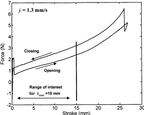
Figure 26: Typical force of a work cycle experiment... 55
Figure 27: Example of data vector truncation... 57
Figure 28: Force difference m ap... 58
Figure 29: Pow er m ap... 59 7
Figure 30: Current consumption m ap. ... 60
Figure 31: Current consumption map, isolevel view, units in milliampere... 60
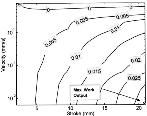
Figure 32: Cycle work output m ap. ... 61
Figure 33: Cycle work output map, isolevel view, units in Joule... 62
Figure 34: Cycle efficiency m ap... 63
Figure 35: Cycle efficiency map, isolevel view, units in percentage. ... 63
Figure 36: Viscoelastic m odel structure. ... 64
Figure 37: Interstitial frame rheological model. ... 66
Figure 38: Structural and interstitial frames model, prediction (dark) vs. experim ent (light). ... 67
Figure 39: Free body diagram of diamond actuator frame. ... 67
Figure 40: Viscoelastic model, prediction (dark) vs. experiment (light), case 1... 70
Figure 41: Viscoelastic model, prediction (dark) vs. experiment (light), case 2... 70
Figure 42: Viscoelastic model, prediction (dark) vs. experiment (light), case 3... 71
Figure 43: Viscoelastic model, prediction (dark) vs. experiment (light), case 4... 71
Figure 44: Viscoelastic model, prediction (dark) vs. experiment (light), case 5... 72
Figure 45: DE actuator thermodynamic system... 73
Figure 46: Diffusive current leakage process. ... 75
Figure 47: Current leakage model predictions (white) vs. experiments (grey). ... 79
Figure 48: Current consumption of considered mechanisms: (a) variable capacitance, (b) conduction leakage, (c) diffusion leakage, (d) mechanical power output and (e) viscous dissipation... 80
Figure 49: Ideal actuator decomposed into active and passive regions... 84
Figure 50: Failure m odes of DE actuators... 86
Figure 51: Film geometry during pull-in instability. ... 87
Figure 52: Example of pull-in failure criterion... 88
Figure 53: Calculated actuation area expansion at failure as a function of area pre-stretch at very high pre-stretch rates (uNI =1.8 s-)'.... ''..'..'.'... 89
Figure 54: Calculated actuation area expansion at failure as a function of area pre-stretch at high pre-stretch rates (uNI =0.094 s-1)--'''...'... 90
Figure 55: Calculated actuation area expansion at failure as a function of area pre-stretch at low pre-stretch rates (kNI =3.3x10 4 S )... 90
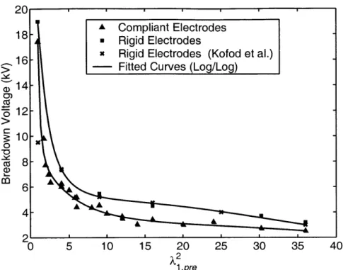
Figure 56: Experimental breakdown voltages for rigid and compliant electrodes
measured at high stretch rate (ANI =0.094 s-1)... ''..''..'....'... 94
Figure 57: Experimental ultimate actuation area expansion vs. pre-stretch area expansion at high stretch rate (ANI =0.094 s-)'....''... 95
Figure 58: Failure analytical predictions for high stretch rate (kNI =0.094 s ) com pared with experimental values. ... 97
Figure 59: Failure analytical predictions for low stretch rate (UNI =3.3x10⁴ S-1) com pared with experimental values. ... 97
Figure 60: Failure analytical predictions for high stretch rate (AUNI =0.094 s 1) with loading stress compared with experimental values of 10 diamond actuators... 99
Figure 61: Failure analytical predictions for low stretch rate (kNI =3.3x10⁴ s-) with loading stress compared with experimental values of 10 diamond actu ato rs... 9 9 Figure 62: Steady state transducer systems: (a) voice coil, (b) DE actuator. ... 104
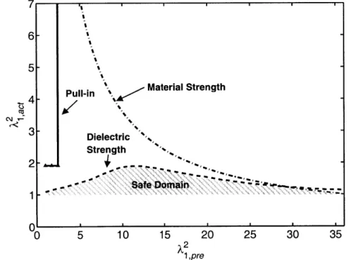
Figure 63: DE actuator design dom ain m ap. ... 106
Figure 64: Diamond actuator scaling: 107 mm vs. 54 mm... 113
Figure 65: Effect of structural efficiency on specific work output... 116
Figure 66: Effect of film thickness on current consumption. ... 118
Figure 67: Film edge crack photograph (4X). ... 119
Figure 68: Film edge cracking m echanism ... 120
Figure 69: Flip-flop bistable m echanism . ... 124
Figure 70: Flip-flop bistable actuator concept... 124
Figure 71: Flip-flop bistable actuator prototype. ... 125
Figure 72: Flip-flop bistable actuator force profiles... 125
Figure 73: Mini-might concept, assembled and exploded views... 127
Figure 74: Mini-might dimensions in millimeters: (a) closed, (b) opened... 128
Figure 75: M ini-m ight m echanism details... 129
Figure 76: M ini-m ight opening sequence... 130
Figure 77: M ini-might bistable actuator prototype... 131
Figure 78: Mini-might bistable actuator force profiles... 131
Figure 79: Transperinal Brachytherapy schematic. ... 133
Figure 80: Perforated guide-plate for manual Brachytherapy. ... 134
Figure 81: Workspace for needle insertion in transperinal prostate cancer treatment. (Courtesy of Daniel Katcher, Brigham and Women Hospital). ... 135
Figure 82: 30 DOF binary crane structure [70]. ... 136
Figure 83: 24 DOF snake-like MRI manipulator concept (in millimeters). ... 137
Figure 84: End effector's x, y, z position of the snake-like MRI manipulator. ... 138
Figure 85: End effector's 6, angle of the snake-like MRI manipulator. ... 138
Figure 86: End effector's O, angle of the snake-like MRI manipulator. ... 139
Figure 87: 7 DOF MRI manipulator prototype... 140
Figure 88: Range of motion of the 7 DOF MRI manipulator prototype... 141
Figure 89: Engineering drawing, structural frame, 107 mm actuator... 155
Figure 90: Engineering drawing, interstitial frame, 107 mm actuator... 155
Figure 91: Engineering drawing, structural frame, 54 mm actuator... 156
Figure 92: Engineering drawing, interstitial frame, 54 mm actuator... 156
Figure 93: Engineering drawing, interstitial frame array, 54 mm actuator. ... 158
Figure 94: Interstitial fram es assem bly jig... 158
Figure 95: Adhesive in interstitial frame hinges... 159
Figure 96: Experimental film stretching setup... 161
Figure 97: Film stretching sequence... 162
Figure 98: Experimental vs. constant volume film thickness... 163
Figure 99: Uniaxial deformation of a rectangular sample. ... 165
Figure 100: Experimental stress/stretch curves for uniaxial extension of VHB 4905/49 10 at different stretch rates. The solid curves superposed on (a), (b) and (c) are curve-fitted Ogden models... 167
Figure 101: Bergstrom-Boyce network A parameters curve fit... 170
Figure 102: Deformation of the passive region model. ... 173
Figure 103: Example of stretch distribution in the passive region. ... 175
Figure 104: Example of engineering stress distribution in the passive region. ... 176
Figure 105: Passive region's deformed shape computed with Adina@ when inner face is: (a) discontinuous, and (b), continuous (not to scale). ... 177
Figure 106: Planar stress in the active region vs. actuation stretch for analytical and F E m odels. ... 178
Figure 107: Schematic of the planar stress in the active region vs. actuation stretch ... 17 9 Figure 108: Microbots mission concept. Image rendering by Gus Frederick... 183
Figure 109: Microbots hopping mechanism. ... 184 10
Figure 110: Changing the attitude of the Microbots using the directional hopping
m echanism concept... 184 Figure 111: DE actuator hopping mechanism. ... 185 Figure 112: Sequence of images of the mobility system prototype performing a
jump. Total cycle time is about 20 seconds... 186
LIST OF TABLES
Table 1: Specifications of a 107 mm diamond actuator with 3 active layers. ... 33
Table 2: Specifications of a 54 mm diamond actuator with 6 active layers. ... 33
Table 3: Current leakage model parameters ... 78
Table 4: Experimental actuation area expansion at failure for low stretch rate, ANI =3.3x 0 s-1 '... '.'... . ... 95
T able 5: Scaling law s verification... 114
Table 6: Best film bonding interface parameters... 121
Table 7: Flip-flop bistable actuator specifications... 126
Table 8: Mini-might bistable actuator specifications... 132
Table 9: Ogden model parameters from uniaxial tests. ... 166
Table 10: Bergstrom-Boyce network B parameters... 171
CHAPTER
1
INTRODUCTION
1.1 Motivation
Future robotics and mechatronics applications will require devices that are simple, robust, lightweight and inexpensive. Current systems using conventional actuators such as electric motors with gears are complex, expensive, heavy, and have high power consumption. A suggested solution for future systems is the concept known as binary
actuation. Binary actuation can be thought of as the mechanical analogy to digital
electronics, where each actuator "flips" between one of two possible discrete states. Systems can be simple since low-level feedback control is virtually eliminated, along with the associated sensors, wiring, and electronics [3,42]. Such devices are fundamentally robust, lightweight, inexpensive, and easy to control. Further benefits of binary actuation using bistable mechanisms are that power consumption is eliminated while the system is in a fixed configuration since actuators can be turned off.
A number of potential applications of binary actuation ranging from space exploration to industrial systems have been proposed [14,16,42]. Figure 1 shows such an application consisting of a 6 legged walking robot for planetary exploration. Each leg is composed of 21 binary joints, each actuated by a binary actuator (not shown for clarity). Laboratory experimental systems along with computational simulations have been developed to demonstrate the principles of binary actuation [42,43]. These studies have shown that real applications will require 10's to 100's of binary actuators, and that the
analysis, planning, and control of such systems are well within the capabilities of modem computation.
Figure 1: Computer Simulation of FSRL's 6 legged walking rover climbing Mars surface [44].
To date, only a few practical applications of binary actuation technology have been developed. Conventional actuators are too large, complex, expensive and heavy to implement in large numbers [24]. Therefore, for the concept of binary robotics to be successful, new cheap, simple, and lightweight actuators must be developed.
Alternative actuation technologies have been considered but all show at least one weakness for binary robotic systems [26]. Shape Memory Alloys (SMA) relies on volume contractions driven by alloy phase changes, a very inefficient process. They are also relatively slow and sensitive to external temperature changes. Ionic polymers change volume when their polymer chains absorb or swell ions. Such systems must be kept in aqueous environments and are slow. Optimized linear electromagnetic systems (solenoids) experienced overheating issues and were heavy. Examples of past binary manipulators developed with SMA and electromagnetic technologies are shown in Figure 2 and Figure 3.
14
2 DOF Flexure Joint 7
a) Single-stage in deployed state b) 4-stage prototype showing flexures and actuators
Figure 2: SMA binary manipulator prototype [76].
I41
n its undeployed stateMagnets
Figure 3: Electromagnetic binary manipulator prototype [26].
In contrast with most alternative actuation technologies, Dielectric Elastomer (DE) actuators have shown good performance and are inherently inexpensive [49,58].
Possible applications of DE actuators vary from medical devices to space robotics. In particular, laboratory demonstrations of blood pumps, imaging systems and
1 DOF Flexure Joints SMA Actuators 15 Chapter 1: Introduction
reconfigurable large space telescopes were studied [24,25,80,84]. A prototype of one such actuated telescope mirror is shown in Figure 4.
Figure 4: DE binary manipulator prototype [84].
Dielectric Elastomer actuators are lightweight, simple, have large displacements and good force capabilities [79,55,32]. Early assessments of ideal DE performance based on 3M's VHB 4905/4910 elastomer, a common material used in DE actuators, suggested:
* extensions of up to 3 times their initial length [79]; " bulk material force-to-weight ratio of 1000:1 [79]; * bulk material specific energy densities of 3-4 J/g [55];
However, practical systems performance is far from the ideal numbers reported above [28,32,36]. Early practical DE actuators showed low reliability, short lifetimes, and low efficiencies [80,84]. Such practical implementation problems suggested that DE actuators were not completely understood and consequently that their design was not capturing their true physics.
The purpose of this thesis is to make binary actuation based on DE actuators practical. To do so, the fundamental mechanisms of DE actuation need to be fully understood. Specifically, the mechanisms responsible for the reliability and performance
16 Chapter 1: Introduction
of practical actuators need to be quantified. Such an understanding is the key to developing DE actuators for binary actuation that reflect DE physical reality.
1.2
Background Literature
This section presents a review of literature on binary actuation and the principal challenges to DE actuation.
1.2.1 Binary Actuation
Binary actuation for mechanical systems was first proposed in the 1960's and 70's [3,67]. Most work done on the subject in the last 30 years has focused on the trajectory planning of binary manipulators which involves searching through a discrete set of configurations. Researchers have provided important results on the kinematics and inverse kinematics of binary mechanisms [14,16,17]. Real time computation has been demonstrated with combinatorial search algorithms and genetic algorithms [42,45].
These early studies as well as many recent ones focused on kinematically constrained actuator arrangements [17,45,64]. In Gruebler's law terms, a kinematically constrained system is one where the number of degree of freedom is equal to the number of actuated joints and each actuator can be actuated without conflict with any other actuators [22]. . The prototypes of Figure 2, Figure 3, and Figure 4 are all kinematically constrained arrangements. After more than 30 years of development, even the simplest kinematically constrained binary systems are still impractical due to inadequate actuation technology.
More recently, over-constrained binary systems were studied. In Gruebler's law terms, an over-constrained system is one where there are more actuated joints than degrees of freedom [22]. Flipping one actuator requires deformation of the system and will generally work only if additional compliance is introduced [51,88]. Limited
experimental work was conducted on over-constrained systems. One experiment studied a single degree-of-freedom (DOF) joint powered by pneumatic cylinders coupled with springs. The system showed the expected dynamic behavior but was bulky, expensive and impractical due to current actuation technologies [88].
Theoretically, over-constrained systems constitute the most general case of binary actuation with kinematically constrained systems representing a small subset where the kinematics allows the actuators to be decoupled. By using redundant actuators, over-constrained systems can potentially develop higher total system stiffness than kinematically constrained systems. Positioning errors could also decrease as the number of actuators increase because of the "elastic average" created by actuator redundancy
[72].
1.2.2 DE Actuator Modeling
In general, reported performance numbers of DE actuators were isolated best-case values. There was no published experimental data showing how working conditions influence performance. In fact, the governing physics of DE actuators has not been completely understood.
The basic mechanism of DE actuators is the electromechanical coupling between electric charges and mechanical forces. This coupling results from two physical mechanisms: Maxwell Stresses and Electrostriction . Studies have shown the electrostriction contribution to be negligible at room temperature and frequencies of about 1 Hz for 3M's VHB 4905/4910, a common material used in DE actuators [33,46]. Maxwell stresses are generated on an elastomer film's surface via electrically charged deformable electrodes and are responsible for DE actuator deformations, see Figure 5.
Electrostriction results from a material's dipole reorientation in an electric field.
The Maxwell stresses are compressive in nature and therefore the film must be pre-stretched to avoid buckling.
Elastomer Film
V Maxwell Stresses
Compliant Electrodes
Figure 5: DE actuator operating principle [38].
Maxwell stresses on DE electrodes have two components: a compressive and a planar stress, both generated by the charged electrodes, see Figure 6 [38,57]. The combined actions of those stresses can be expressed by an equivalent Maxwell pressure,
P, given by [38,57]:
P = EE (1.1)
where eo is the free-space permittivity (8.85x 10-42 F/m), Fd is the material's
dielectric constant, V is the voltage applied across the electrodes, and u is the film thickness.
Equation (1.1) is valid for uniform electrical charge distribution on infinitely large electrodes and uniform film thickness. It should be noted that Eq. (1.1) represents only an approximation of the real film loading [48]. Its simplicity and accuracy makes it the generally accepted electromechanical coupling model for most DE actuators.
Chapter 1: Introduction
19 19 Chapter 1: Introduction
Positive Electrode
x, y
Negative Electrode
Figure 6: Maxwell stresses acting on DE actuators [80].
Early analyses of DE deformation used linear (Hookean) material models but were shown inadequate to describe the significant nonlinear behavior of DE actuation (large displacements and nonlinear elasticity) [37,57,74]. These issues can be addressed with continuum mechanics methods [2,30,53]. Accordingly, researchers have used hyper-elastic material models like the Mooney-Rivlin and Ogden models to study simple DE actuator shapes [24,25,32,59,85]. Those models were shown to be capable of representing experimental data of DE actuators under constant stretch rates (deformation rate). However, frequency response experiments have shown significant displacement attenuation with increasing frequency or stretch rate, with up to 90% attenuation at 10Hz
[35,46]. This important stretch rate dependence is attributed to viscoelasticity and should
obviously be accounted for in DE analysis.
Viscoelastic effects of DE films were briefly investigated using a Mooney-Rivlin hyper-elastic model coupled with a Maxwell viscosity model [40]. This analysis considered uniaxial deformation with stretches2 of up to 1.8. Other similar studies were conducted up to stretches of 3.0 [87]. The deformation of expanding DE circles was studied using various hyper-elastic models coupled with quasi-linear viscoelasticity within Finite Element Models [85]. The extensions considered in these models were
The term "stretch" is a measure of deformation used in continuum mechanics and defined by: A = - .
iP
substantially lower than typical DE actuators extensions that can reach stretches of 5.0. Most importantly, they addressed geometries that are not representative of practical actuators, and were not experimentally validated over real working conditions. Other material models of nonlinear viscoelastic materials undergoing large deformation have been developed but have not been applied to DE materials [6,7,20]. A detailed and comprehensive description of viscoelasticity's role on DE actuators performance has not been developed prior to this study.
Besides viscoelasticity, another important physical mechanism affecting DE actuator performance is even less understood: current leakage through the film. Such currents are measured experimentally but no physical explanation of their nature has yet been given and their quantitative impact on actuator efficiency is unknown [37,57,80,84].
In summary, proper DE performance models have yet to be developed and validated experimentally. The following fundamental effects need to be considered in these models:
1. very large deformations; 2. nonlinear elastic behavior; 3. viscoelasticity;
4. current leakage.
1.2.3 DE Failure Problems
The vast majority of DE actuator development so far has consisted of developing
new actuator shapes and exploring potential applications
[12,28,34,36,55,56,61,62,71,79,80,84]. After more than 10 years of research and impressive laboratory performance results, DE actuators are still not available commercially as off-the-shelf design components, presumably because of their reliability
problems. Indeed, experiments have shown "infant mortalities"3 of 30%, shelf lives of about a week for high performance actuators built with highly pre-stretched films, and most importantly, erratic and misunderstood failures during operation [80,84].
The first investigations of DE failure focused on a failure mode called pull-in. A pull-in failure occurs when the Maxwell pressure becomes greater than the film's compressive stress. This positive feedback leads to an unstable compression of the elastomer material and catastrophic failure. This failure mode was investigated with linear (Hookean) stress/stretch models [37,57,74]. However, these models were inadequate and predicted pull-in failures at about half the extensions observed experimentally [55,79].
More recently, pull-in failure was briefly investigated using hyper-elastic continuum mechanics [85]. This study predicted pull-in to be of no concern because it should occur above the material dielectric strength. However, experimental evidence presented in this thesis shows pull-in to be an important and observable failure mode.
Clearly, the circumstances leading to pull-in failures have not been understood.
The role of viscoelasticity on DE actuator failures has not yet been investigated. Previous studies addressed these failures by treating them as purely elastic systems
[37,57,74].
The role of film dielectric strength on maximum extension was studied and its important effect on DE extension is illustrated by the figure of merit: E2Y-1 where E is the maximum electric field or dielectric strength, and Y is the apparent Young's modulus (if the material was linear) [74]. Since the dielectric strength is squared, it strongly affects DE performance limits. Experimental results have shown that the dielectric strength of VHB 4905/49 10 increases from about 40 MV/m to 240 MV/m when stretched to 36 times its initial area [33,60], a major positive impact when viewed in light of
3 Immediate failure upon first voltage application.
E2Y1 . Failure models including variable dielectric strength have not yet been developed.
In summary, past DE research has mostly addressed new applications rather than practical failure problems. Hence, failure modes still need to be identified and the conditions in which they occur have to be described. The impact of failure modes on DE performance levels is also unknown. Any attempt to study DE failure should address the following fundamental effects:
1. very large deformations; 2. nonlinear elastic behavior; 3. viscoelasticity;
4. variable dielectric strength.
1.2.4 DE Actuator Design
Prior to this thesis, DE actuators have been seen as simple nonlinear elastic materials with almost perfect electrical isolation properties. An example of a recently-studied actuator is shown in Figure 7. These actuators were used in the binary manipulator prototype of Figure 4. This particular actuator design uses a pre-stretched film preloaded by a pair of compliant frames. The Linear Bistable Element (LBE) counteracts the forces due to film stiffness in order to increase output strains. Such actuators are capable of bidirectional forces of about 0.5 N (for a single film layer) and output strains of about 60% [84]. Even if they used bistable components (LBE), these early actuators were not truly bistable because they had to be kept activated to maintain their extended position. This operation scheme was consistent with the understanding at that time and ignores the fundamental mechanisms of viscoelasticity and current leakage. As a result, DE actuators appeared impractical due to unexplainable failures and viscous relaxation.
Voltage OFF
LBE Voltage ON
a) CAD representation showing film and b) Prototype shown before and after
electrodes actuation
Figure 7: DE actuator for binary actuation developed in 2002 [84].
DE actuator designs were not rigorously characterized in the literature. It was
therefore difficult to compare various concepts and evaluate progress. For example, the principal design objective of any DE actuator is to optimize work output for a given actuator mass. This objective is of critical importance for mobile and weight sensitive applications but, prior to this thesis, there was no data to precisely described actuator work output performance [84]. Further, there were no useful design tools to help the
designer size a DE actuator for a given application.
Even if incomplete, the early work on DE actuators led to important design principles:
" The positive effect of film pre-stretch on actuation performance [35,60].
" The potential output strain enhancement by using asymmetric
pre-stretches. The idea is to highly pre-stretch the film in its passive direction and to leave it almost unstretched, and therefore soft, in its active direction
[35,60].
24
* The use of nonlinear restoring forces to cancel the film stiffness in order to amplify actuator displacement [59,80]. By canceling the film stiffness, the actuator could, in theory, move freely until it fails.
In summary, a set of physics-based DE design tools did not exist, largely because DE actuator mechanics were not completely understood. Consequently, the question of
how to design reliable, high performance DE actuators has been unanswered.
1.3
Contributions of this Thesis
This thesis develops fundamental physical models of DE actuation and addresses mechanical design issues essential to their successful application.
The critical problems of actuator reliability and failure mechanisms are addressed. Analytical models of the physical mechanisms of DE actuation are developed and their predictions are compared against experimental data to assess their validity. The performance of DE actuators is also characterized experimentally over a large range of working conditions.
These analytical models are used to improve the design of DE actuators through new design tools and system concepts. Tools like design domain maps for performance trade-offs, scaling laws and a design optimization metrics are developed. New design concepts that exploit the strengths and weakness of the technology are developed. In particular, a novel bistable mechanism is proposed to allow DE actuators to function intermittently, an essential condition for their reliability. An application example to MRI manipulation shows bistable DE actuators to be a valid approach to binary robotics and mechatronics.
1.4
General Constraints and Assumptions
The performance of DE actuators depends on the film material properties. Many polymer film materials were studied in the past 10 years, and the material giving the best performance in terms of energy output for a given film mass is 3M's VHB 4905/4910
[9,11,35,37,38,39,58,75,77,89]. Briefly, the key properties of this material are its large deformation capability and high dielectric strength. Moreover, VHB 4905/4910 is commercially available as an adhesive tape, and does not require elaborate fabrication processes such as mixing, degassing, centrifuging, and curing. Therefore, this thesis uses this material as a reference material.
The mechanical properties of VHB 4905/4910 are temperature sensitive, varying by three orders of magnitude from -500 to 1250C [89]. This thesis is limited to room temperature. Also, the mechanical properties are assumed isotropic before pre-stretching.
The film is incompressible. The rubber-like material VHB 4905/4910 has a Poisson's ratio of 0.49, which is very close to the incompressible value of 0.5 [1].
The film dielectric constant, Ed' of VHB 4905/4910 was recently found to decrease with film stretching. Variation by a factor of up to two followed by partial recovery was reported [19]. No models have been proposed and more data is needed to fully understand this effect. Therefore, this thesis uses a fixed dielectric constant of
ed=4.5 [33].
1.5
Thesis Organization
The thesis has seven chapters. Chapter 1 presents motivation and background for the thesis. It also describes the past work done to understand DE actuators and to address their failure problem. Chapter 2 presents ideas and concepts used in analysis throughout this thesis. Chapters 3 and 4 address fundamental modeling issues. Chapter 3 starts with
a detailed study of the physical mechanisms influencing DE performance and Chapter 4 follows by investigating the crucial question of DE actuator reliability. Chapter 5 addresses the question of how to design reliable, high performance DE actuators. New DE actuator design tools are developed from the fundamental results. Chapter 6 integrates DE actuators into binary robotic systems by using bistable mechanisms. An application example to Magnetic Resonance Imaging (MRI) manipulation illustrates the technology capabilities. Finally, Chapter 7 summarizes the thesis and suggests avenues for future research.
CHAPTER
2
FOUNDATION OF DIELECTRIc ELASTOMER
ANALYSIS
2.1
Introduction
This chapter presents basic ideas used in DE actuators analyses throughout this thesis. First, the diamond actuator concept used as a reference actuator in most experimental work is presented. Second, the continuum mechanics modeling framework required to handle the large displacements and nonlinear material properties is presented.
2.2 Diamond Actuator Concept
As mentioned in Chapter 1, many DE actuator concepts have been proposed in the past ten years. The rolled and planar actuator classes have shown particularly good performance. The rolled actuator concept consists of wrapping a long DE film around a pre-loaded coil spring, see Figure 8 [34,55,56,62].
Coil Spring Long Film with Electrodes
Figure 8: Rolled DE actuator [55].
The planar concept consists of bonding many individual planar film layers onto a preloaded compliant frame (i.e., see Figure 7 on page 24) [80,83,84]. The main
advantage of these concepts is their ability to pack many active layers in a small space. The performance of DE actuators depends greatly on actuator geometry. Hence, this thesis focuses on a specific class of planar actuators called diamond actuators. Such actuators consist in a 4 bar linkage geometry as shown in Figure 9. The film occupies the inside space of the diamond and is preloaded by a pair of elastic bands. Under voltage application, the Maxwell pressure compresses the film, causing its area to expand. As a result, the film planar area must increase because the film's volume is constant:
Aat > Apre The choice of this actuator geometry is motivated by the following reasons: " The diamond shape provides a uniform stress/stretch state during actuator
deformation (this is demonstrated in the diamond actuator kinematical development presented in Section 2.3.2). Hence, the film is loaded uniformly everywhere and thus the entire film's mass contributes equally and optimally to work output production. In contrast, rolled actuators are under 3D states of stress. Their high film pre-stretch in the hoop direction translates into a gradually increasing compressive stress from the outer radius to the inner radius, similar to a thick-wall cylindrical pressure vessel. Moreover, uniform stress/stretch eases actuator modeling because Finite Element Models are not required.
* The diamond shape has large output strains for a given film area expansion [80]1. Diamond actuators thus exploit the large deformations capabilities of VHB 4905/4910. Large strains maximize work output
1 Part of the development of the diamond frame actuator was done in collaboration with John Vogan. The reader is referred to his thesis to learn more about the nonlinear restoring force of diamond actuators [80].
production and are also very important to developing high performance binary robots [43,76].
* The diamond shape provides a convenient mounting location for preloading elastic bands giving a nonlinear restoring force. The elastic bands act like an over-the-center mechanism acting on the central hinges, see Figure 9. The moment arm distance with the central hinges increases with actuation, dact > dpre' thereby increasing the restoring moment. Such
nonlinear restoring forces cancel the film stiffness making the film apparently free-floating and thus maximize actuation strains [59,80,84]. This unique feature of diamond actuators eliminates the need for additional complex, nonlinear springs to compensate the film stiffness such as used in early DE actuators [84].
Compliant 4
Bars Linkage
Output
Elastic Bands Displacement
a) Closed, 0kV b) Opened, 10 kV
(Pre-stretched Configuration) (Actuated Configuration)
Figure 9: Diamond actuator schematic.
The diamond actuator conceptualized in this thesis has the ability to use multiple film layers to increase its force capabilities. Each film layer is assembled with a pair of thin interstitial frames, see Figure 10. These sub-assemblies are then inserted between a
pair of structural frames, see Figure 11. The interstitial and structural frames use compliant flexure joints to provide angular motion.
Interstitial Frames
Film0s
Figure 10: Film layer sub-assembly.
Assembled Actuator
Film Layers with Interstitial Frames
Figure 11: Multi-layer diamond actuator assembly.
Two diamond actuator sizes are considered in this thesis. Diamond actuator sizes are referred to by their diamond major axis and the sizes considered are 107 and 54 mm. A triple active layer prototype of 107 mm is shown performing 100% extensions on Figure 12. The performance characteristics of the two actuators are listed in Table 1 and
Table 2. The test velocities were scaled with size to insure identical stretch rates (see Section 5.4).
Parts manufacturing and assembly details are discussed in Appendix A. Due to hand-manufacturing limitations, the number of active layers was limited to low values of about 6 layers for the 54 mm actuator. There are no fundamental limits to the number of active layers. With proper manufacturing techniques (not yet developed), actuators with 100's to 1000's of layers are possible.
Extensive fatigue tests under various working conditions were not conducted in this thesis. However, a single preliminary fatigue test was conducted to verify if the performance of diamond actuators can be repeated. A 107 mm actuator using a single active layer was subject to a 10 kV square wave with a period of 8 s and a duty cycle of 30%. The actuator survived 15,200 cycles at 60% strain under no external load. Such high cycles suggests that the performance of diamond actuators is repeatable. Failure eventually occurred by cracks at the film/frame interface. This local failure mode is discussed in Section 5.7.
oltage
off
Itage on
Figure 12: Diamond actuator prototype under 100% strains.
Table 1: Specifications of a 107 mm diamond actuator with 3 active layers.
Parameters Values Units
Pre-stretches: 1 'pre XA2, pre 5x2.2
**'*** ... ... ... .... * ... ... * ... ... ... ... ... ...
Assembly Initial minor axis, y,, 18 nun
... I ... I ... ...
Initial film thickness 1.5 Min
3 Films 0.43 g
... ... ... ... ... ... I ...
6 Interstitial frame 3
(0.25mm)
... .... ... ... ...
Mass ... 2 Structural frames ... ... ... 9 ... ...9
2 Elastic bands 3 9 ... ... -... ... -... ... ... I ... Fasteners 1.3 ... I ... I ... ... ... Z ... Total 16.7 9 Average force ... ... --... .... ... -2.1 ... ... ... ..... N... Stroke 27 Mm B e s t ... ... ... ...
P e rfo rm an c e S tretc h (stra in ) 2 -.5 ( -1 -5 0 -- % .- ) .. ... ... ...
@ ) 1 .6 m rn /s F -o r c -e --t -o --w -e -i -g -h -t r -a -t i .. o ... ... ... ... 1 -3 ... ... ...
an d 10 k V P -e -a -k e ffi c .. i -e -n .- c .. y ... -... ... I -8 .- % ... ... ... ...
0.12 Jlg of film
... ... ... ... ... ... .... .... .... .... .. ...
S p e c ific w o rk o u tp u t ... 0 ... 0 0 .. 3 ... J/ .g o f a .c .t u ...
Table 2: Specifications of a 54 mm diamond actuator with 6 active layers.
Parameters Values Units
Pre-stretches: 1 'pre X/12, pre 5x2.2
... * ... -... ... ...
Assembly Initial minor axis, yo 9 mm
... ... .... ... ... ... I ... -...
Initial film thickness 1.5 nun
6 Films 0.24 g ... ... ... ... .. ... 12 Interstitial frames 2.0 9 (0.08mm) .... .... ... .... ... ...
M ass 2 Structural fram es 5.9 ...
... ... ... ... 2 Elastic bands 1.4 9 ... ... ... .... ... Fasteners 1.3 9 .. .... ... ... ... ... ... Total 10.9 9 Average force -1.9 N ... ... .... ... I ... ... .... ... Stroke 12 mm B e s t ... I ... ... ... P e rfo rm an c e S -tre t -c -h ( -s -t -r .a -i -n -) ... .... .... ... 2 .- .-5 ( 1 5 -0 -% -) ... ... ...
@ 0 .8 m m /s F o -r -c -e ---t o ---w .- e -ig -lit r -at -i -o ... ... ... 1 8 ... ... ...
Peak efficiency 18% a n d 1 0 k V ... ... .... .. ... .... .. .. ... .. .... ... ... ... .. ... 0.10 J/g of film S p e c ific w o rk o u tp u t ... ... ... .... 0.002 1 J/g of actuator I 33 Chapter 2: Foundation of Dielectric Elastorner Analysis
2.3 Continuum Mechanics: Kinematics
As pointed out in Chapter 1, DE actuators undergo large displacements. Classical Hookean mechanics is not valid and advanced continuum mechanics methods are required [30,53]. This section describes the kinematics concept used in continuum mechanics. In particular, the kinematics of diamond actuators and ideal actuators are described. These notions will be used later in Chapter 3 and 4 respectively.
A deformation is the time-space process of a body undergoing a change in its physical configuration over time as shown in Figure 13. The vector map X is called the
motion of the body B and maps a material point defined by a vector X in the reference
configuration to a new spatial location defined by a vector x in the deformed configuration. The reciprocal vector map X- is the inverse motion. The Euclidian reference frame e , ,e2 e3 is considered inertial.
x =X(X,t) X = x1 (x,t) Reference 3 - Deformed Configuration Configuration -Time t = 0 -Time t
fe3
X1 el e2 X2X2Figure 13: Illustration of a deformation, adapted from [30].
Consider a vector dX between two infinitesimally close points on the body in the reference configuration whose deformation lead to a corresponding infinitesimal vector, 34 Chapter 2: Foundation of Dielectric Elastomer Analysis
dx, in the deformed configuration as shown in Figure 13.
expressed by their lengths times a unit vector: dX = dSe and dx = dse'. The stretch, A,
along the unit vector's direction is the ratio of the lengths between the deformed and reference configurations [30]:
A ds (2.1)
dS
Extension and compression deformations respectively correspond to A > 1 and A<1.
A fundamental concept of hyper-elasticity is the deformation gradient tensor,F, defined by: F = a(Xt) = V(X,t) AX ax,
ax2
a2 ax, ax 3 ax,ax,
aX2 ax 2 aX2 ax 3 aX2axi
aX3 ax2 ax3 ax3 aX3 (2.2)The deformation gradient tensor can be decomposed into a pure rotation and a
pure stretch by the polar decomposition [30]:
F
= RU = VRChapter 2: Foundation of Dielectric Elastomer Analysis
(2.3) These vectors can be
where R is the rotation, U is the right stretch tensor, and V is the left stretch tensor. The principal stretches, A1,22,23, are defined by the spectral representation of
U2 [30]:
3
U2 = LA2N, 0Nj (2.4)
where N are the associated eigenvectors expressed in the reference configuration. The eigenvectors define the mutually orthogonal principal directions of
stretch along which the principal stretches are measured.
All analysis in this thesis use deformations which can readily be described in the principal directions. Such deformations are called pure stretch and their rotation tensor is the identity: R = I. Their deformation gradient tensors are diagonal with diagonal elements being the principal stretches:
~Al 0 0
F= 0 22 0 (2.5)
0 0 A3
The kinematics of incompressible materials like VHB 4905/4910 is further simplified because, to maintain a constant volume, the determinant of the deformation tensor must equal one for all deformations: detF = J = 1. The determinant is given by the product of the principal stretches which is equal to one for all deformations:
/,A' = 1 (2.6)
The deformation of a general DE film is decomposed into a pre-stretch and
actuation deformations, see Figure 14. The film's dimensions in the reference configuration are expressed in the X1, X2, X3 system. The dimensions in the
pre-stretched or actuated configurations are expressed in the x1,x2,X3 system. For pure
stretch deformations such as considered in this thesis, the coordinate system directions
X1,X 2,X 3 and x1,x2,X3 coincide with the principal directions, 1,2,3. The principal
stretches of the pre-stretch, actuation and total deformations are defined by the dimensionless ratios given by:
1,pre A2 2,pre X3,pre
, X 2
-X 3
,lact - 1,act A2,act X2,act A3,art X3,act(27
1, pre r 2,pre 33,pre
1,act X2,at 3,act
2= tot Xi 2,-ot X2 , 3
Xpr X2r X,r
It can be shown using Eq. (2.7) that the principal stretches of the three deformations are linked by:
,tot ,pre lact 22,tot = 2,pre 2 ,act 3,tot = A3,pre 3,act (2.8)
The film must be pre-stretched prior to actuation to prevent buckling under the compressive Maxwell pressure. The pre-stretch deformation is an imposed biaxial deformation that produces principal true stresses2 in the pre-stretched configuration, Cipre, 2,pre , 03,pre, where 0 3,pre =0. For isotropic materials like VHB 4905/4910, the principal directions of stretch coincide with the principal directions of stress [30]. The
2 In this thesis, "true" stresses or Cauchy stresses are labeled by " a " while engineering stresses or First Piola-Kirchoff stresses are labeled by " S ". The difference is the area " A " defining the stress: one is expressed in the reference
configuration, S = F/Arejerence , and the other is the deformed configuration, a-=
pre-stretched configuration is perturbed by the Maxwell pressure, P, resulting from voltage application. The film further deforms and the stresses in the actuated configuration reach a new equilibrium, ,t, 2,act ' 03,act .
Total Deformation
l t A2,,,t A3,t,
Pre-stretch Actuation
Deformation Deformation
A'pr~ pr ,pre A actA2,aptrear
al~pre 2pre
Pre-stretched Configuration
Figure 14: Deformations of a general DEfilm.
X3,x3
XIxI X 2,X2
U3ac = P
T
The kinematical descriptions of two actuators used in this thesis are given bellow.
2.3.2
Diamond Actuators
The polymer films of diamond actuators (see Section 2.2) are under biaxial extension such as shown in Figure 15. Characteristic dimensions are the diamond minor axis, y , the film thickness, u , edge length, 1, and angle, 6.
Chapter 2: Foundation of Dielectric Elastomer Analysis
Reference Configuration U2,act Actuated Configuration 38
Y, y U3,act .-- r2 pre CT2,act alac Y ', X Xr Refere rchdActuaed
Confi Upure Cngan Ju
Pre-stretch Actuation
Deformation Deformation
,kpreA,pre' ,pre A,act A,actA3,act
Total Deformation ,
1tOt ,tot ,tot
Figure 15: Deformations of a diamond actuator.
All deformations of the diamond actuator shown in Figure 15 are pure stretch and
the principal directions 1,2,3 thus coincide with the X, Y, Z and x, y, z directions. The planar pre-stretches, ip, and 2 ,,pr, are independent design parameters applied to the
film before assembly, see Appendix B. The incompressibility relation, A122A =1, gives
the corresponding thickness pre-stretch:
13,pre = 1 (2.9)
AL, pre 22,pre
The actuation stretches are uniform on the film's surface. Consider two points, a and b taken on the side of a diamond actuator as shown by Figure 16. The x coordinate of those two points are shown in two configurations corresponding to opening angles, 00
and 0. The x direction stretches between these configurations are:
Axa = XaO Axb = XbO (2.10) Expressing angle 0 gives: ,1X,a
the x coordinates in terms of diamond side length 1 and opening
1 cos0 cos0 _1l cos0 cos0 (2.11)
la cos00 cos 0 xb cos00 cos 0
The length terms cancel making the stretches of both points equal and solely dependant on actuator opening angles 00 and 0. The same reasoning can be applied to the y coordinate where the a and b stretches are given by: Aya = Ab = sin0. The
sin 00
actuation stretches do not depend on the x -y positions and are thus uniform.
y
aa
b b
0 0
Figure 16: Actuation stretches of diamond actuators.
The actuation stretches are thus given by: cosO 1act= cos 0 0 _ sinO sin 60
where 00 is the angle in the pre-stretched configuration. The total stretches are given by:
A1tot , A I re ,act A2,tot = A2,pre A2,act A3,tot = 1 (2.13)
3,tot 3,tot
The total stretch in the z direction conveniently gives the deformed film thickness in terms of its initial thickness, U
u = UA3,tot (2.14)
2.3.3 Ideal Actuators
Ideal actuators consist of a small conductive circle coated in the center of a large
pre-stretched film as shown in Figure 17 (to be precise, these devices should not be called actuators as they cannot do external work). Under Maxwell pressure, the expanding
circle's radius increases from its pre-stretched value, rpre, to its actuated value, ract .
Al
'+1
Chapter 2: Foundation of Dielectric Elastomer Analysis
1 1'"rt 41 2a a
(2.12)
Figure 17: Ideal actuator.
The deformation of the active region (conductive circle) is illustrated in Figure 18. The dimensions in the reference configuration are expressed in the R,e,Z system.
The dimensions in the pre-stretched and actuated dimensions are expressed in the r, 0, z system.
Total Deformation
A1,tot 2,tot A3,tot
Pre-stretch Actuation
Deformation Deformation
A,pre ,pre ,pre 1,act 2,act ,a ct
U pre Z,Z
A
R,r (,0 01,pre Reference Configuration Pre-stretched Configuration a*,act Actuated ConfigurationFigure 18: Deformations of the active region of an ideal actuator.
The pre-stretches are equibiaxial A,, =22,,re and the passive region is
axisymmetric. The active region actuation deformation is thus equibiaxial: 2
1,ac, = A2,a,, The circular active region remains circular during actuation.
42
Chapter 2: Foundation of Dielectric Elastomer Analysis
act
![Figure 1: Computer Simulation of FSRL's 6 legged walking rover climbing Mars surface [44].](https://thumb-eu.123doks.com/thumbv2/123doknet/14745853.578144/14.918.192.703.184.487/figure-computer-simulation-fsrl-legged-walking-climbing-surface.webp)