HAL Id: insu-03094631
https://hal-insu.archives-ouvertes.fr/insu-03094631
Submitted on 4 Jan 2021HAL is a multi-disciplinary open access archive for the deposit and dissemination of sci-entific research documents, whether they are pub-lished or not. The documents may come from teaching and research institutions in France or abroad, or from public or private research centers.
L’archive ouverte pluridisciplinaire HAL, est destinée au dépôt et à la diffusion de documents scientifiques de niveau recherche, publiés ou non, émanant des établissements d’enseignement et de recherche français ou étrangers, des laboratoires publics ou privés.
Microstructures of bedding-parallel faults under
multistage deformation: Examples from the Southeast
Basin of France
N. Lemonnier, Catherine Homberg, Vincent Roche, Anne-Marie Boullier,
Johann Schnyder
To cite this version:
N. Lemonnier, Catherine Homberg, Vincent Roche, Anne-Marie Boullier, Johann Schnyder. Microstructures of bedding-parallel faults under multistage deformation: Examples from the Southeast Basin of France. Journal of Structural Geology, Elsevier, 2020, 140, pp.104138. �10.1016/j.jsg.2020.104138�. �insu-03094631�
Journal Pre-proof
Microstructures of bedding-parallel faults under multistage deformation: Examples from the Southeast Basin of France.
Lemonnier N, Homberg C, Roche V, Rocher M, Boullier A. M, Schnyder J
PII: S0191-8141(19)30492-4
DOI: https://doi.org/10.1016/j.jsg.2020.104138 Reference: SG 104138
To appear in: Journal of Structural Geology
Received Date: 22 November 2019 Revised Date: 6 July 2020
Accepted Date: 6 July 2020
Please cite this article as: N, L., C, H., V, R., M, R., M, B.A., J, S., Microstructures of bedding-parallel faults under multistage deformation: Examples from the Southeast Basin of France., Journal of
Structural Geology (2020), doi: https://doi.org/10.1016/j.jsg.2020.104138.
This is a PDF file of an article that has undergone enhancements after acceptance, such as the addition of a cover page and metadata, and formatting for readability, but it is not yet the definitive version of record. This version will undergo additional copyediting, typesetting and review before it is published in its final form, but we are providing this version to give early visibility of the article. Please note that, during the production process, errors may be discovered which could affect the content, and all legal disclaimers that apply to the journal pertain.
Microstructures of bedding-parallel faults under multistage deformation: Examples 1
from the Southeast Basin of France. 2
3 4
Lemonnier N. 1, Homberg C. 1*,Roche, V. 2, Rocher M. 3, Boullier A. M. 4, Schnyder J. 1
5 6
1: Sorbonne Université, CNRS-INSU, Institut des Sciences de la Terre de Paris, ISTeP UMR 7193, 75005 Paris,
7
France.
8
2: Fault analysis Group, UCD School of Earth Sciences, University College of Dublin, Belfield, Dublin 4,
9
Ireland.
10
3: Institut de Radioprotection et de Sûreté Nucléaire, PSE-ENV/SEDRE/UEMIS, BP 17, F-92262
Fontenay-aux-11
Roses Cedex, France.
12
4: ISTerre, CNRS, Université Grenoble Alpes, F-38041 Grenoble, France.
13 14
* corresponding author 15
16
Keywords: Bedding-parallel faults, microstructures, clays, Southeast Basin of France, crack-seal
17
veins, opening fractures. 18
19
Abstract
20
We conducted a microstructural analysis of bedding-parallel faults (BPFs) in Mesozoic clay-rich 21
layers of the Southeast Basin of France. Various microstructures are recognized in thin sections under 22
a petrographic microscope and by cathodoluminescence. The microscale observations are combined 23
with outcrop observations from previous studies to provide insight into the origin of the BPFs and 24
their evolution during successive phases of deformation in a basin that had a polyphase tectonic 25
history. The BPFs have slipped while normal faults were formed during the Oligocene extension. 26
Then, another phase of slip occurred later during the basin inversion. These two phases of deformation 27
are expressed by recurrent crack-seal veins, pull-apart veins and stylolites. In addition, calcite veins 28
with an elongate blocky morphology suggest an opening normal to bedding before the reactivation. 29
The BPFs have initiated in clay layers that were shallow dipping. Such conditions may appear 30
mechanically unfavourable for an opening normal to bedding or a shearing parallel to bedding. We 31
suggest that the role of rock anisotropy is critical. This study furthermore demonstrates that BPFs can 32
be long-lived brittle structures that may record successive tectonic events. 33
34
1. Introduction
35
Bedding-parallel faults (BPFs) are shear planes lying sub-parallel to bedding in multilayer 36
sequences. They are usually observed in sedimentary basins in weak and compliant layers, and 37
particularly in clay-rich layers (e.g., Gale et al., 2014). Typically, the shearing component is 38
recognized through the presence of slickenlines at the outcrop scale (Tanner, 1989; Evans, 1994; 39
Séjourné et al., 2005; Aydin and Engelder, 2014) and crack-seal veins at the microscopic scale
40
(Fowler et al., 1996; Koehn and Passchier, 2000; Fagereng and Byrnes, 2015). The amount of
41
displacement that is accumulated on the BPFs is usually unknown because they lie parallel to bedding, 42
a configuration that precludes the occurrence of displaced sedimentary interfaces. Nevertheless, few 43
studies describe BPFs offsetting other fractures which provide markers for measuring displacement 44
(Ferrill et al., 2000; Wibberley et al., 2007; Delogkos et al., 2017; 2018). Based on such cross-cutting 45
relationships, Delogkos et al. (2018) demonstrated that BPFs are segmented, display displacement 46
gradients along their traces and die out at tips. BPFs appear therefore to have similar characteristics to 47
other types of faults, which is why we refer to such structures as bedding-parallel faults, rather than 48
bedding-parallel slips or bedding-parallel veins as it is commonly used in the litterature. 49
The presence of BPFs can influence fractures and fluid flow in basins and can be of critical 50
importance in the frameworks of waste disposal sites, hydrocarbon reservoirs, or fluid injection 51
operations. A variety of influences have been demonstrated. For example, BPFs can modify fault zone 52
structures due to the process of fault restriction (Gross et al., 1997; Roche et al., 2017) and the 53
removal of wall rock asperities (Waterson et al., 1998; Delogkos et al., 2017). BPFs can control the 54
segmentation of hydraulic fractures and the associated microseismicity during fluid injection 55
operations in shale (Rutledge et al., 2015; Rutter and Mecklenburgh, 2017; Stanek and Eisner, 2017). 56
They can either act as a preferential fluid pathway along the beds during dilatational movement or 57
inhibit flow across bedding due to their mineralization (Cox et al., 1991; Cosgrove, 1993; Sibson, 58
1996; Rutter and Mecklenburgh, 2017). Finally, because they often occur as a set of several planes
59
(e.g., Tanner, 1989; Nicol and Nathan, 2001; Delogkos et al., 2018), BPFs can create a complex 60
permeable mesh in the rock medium and affect permeability anisotropy. 61
To evaluate the impacts of bedding-parallel faults on fracturing and fluid flow throughout the 62
history of a basin, one is required to assess their origin and their subsequent evolution during 63
deformation history. However, this is not always straightforward because the BPFs can have various 64
origins. They may occur, for example, with flexural-slip folding due to layer-parallel shortening or 65
thrusting (e.g., Tanner, 1989; Fowler, 1996, Koehn and Passchier, 2000), in the rock volume 66
surrounding normal faults due to fault-related folding (e.g., Watterson et al., 1998; Ferrill et al., 2007; 67
Smart et al., 2009; Delogkos et al., 2018) and during gravity-driven deformations (e.g., Alsop et al.,
68
2020).This diversity of context of formation raises critical questions concerning (i) the origin of BPFs
69
in areas of superimposed deformation stages; (ii) the relative timing of BPFs and more steeply dipping 70
faults; and (iii) the evolution of the BPF internal structures during deformation history. 71
In this paper, we describe BPFs in multilayered clay/limestone sequences from three different 72
areas. Previous outcrop observations from the same sites have been detailed in Roche et al. (2012a), 73
(2012b) and (2017). Here, we focus on the microstructures of the BPFs and interpret their kinematics
74
based on previous microscopic observations of bedding-parallel veins (e.g., Labaume et al., 1991; 75
Fowler, 1996; Koehn and Passchier, 2000; Fagereng and Byrnes, 2015) and other veins (e.g.,
76
Passchier and Trouw, 2005; Bons et al., 2012). The studied areas lie in the Southeast Basin of France
77
which has a polyphase tectonic history. By combining the microscale and the outcrop observations, we 78
provide insight into the origin and evolution of BPFs during a complex deformation history. 79
80
2. Geological setting and methodology
81
2.1. Geological setting
82
The 40 000 km2 Southeast Basin of France (Fig. 1) developed during Mesozoic time due to the 83
opening of the western Tethys (or Ligurian Tethys), with up to 10 km thick sediment infill 84
accumulated in the basin (Dubois and Delfaud, 1989). Extension began in the Early Triassic and lasted 85
until the Mid Cretaceous, with a main rifting phase in Early–Mid Jurassic time, followed by several 86
minor extensional periods (e.g., Debrand-Passard et al., 1984; Dubois and Delfaud, 1989; Homberg 87
et al., 2013). Folding and thrusting occurred during the Pyrenean and Alpine orogenies, with a
paroxysm during Late Cretaceous-Eocene and Miocene times, respectively (Ford and Stahel, 1995). 89
The contractional deformations were interrupted during the Upper Eocene-Oligocene by a major 90
rifting event that developed widely in Western Europe (Bergerat, 1987). The Valence Graben near the 91
studied areas (Fig. 1) is an example of a rift segment formed during this period (Séranne, 1999). 92
The BPFs have been studied in three sites, referred to as Saint-Didier, Trescléoux and 93
Espréaux. The sites are located in the western margin (Saint-Didier) and the Vocontian trough 94
(Trescléoux and Espréaux), a sub-basin of the Southeast Basin of France (Fig. 1). The host rocks 95
consist of alternating clay-rich layers and limestone layers of Late Oxfordian age in Saint-Didier and 96
Trescléoux sites and Hauterivian age in Espréaux site. The layers are shallow dipping (ca.10°) in 97
Trescléoux and Saint-Didier and have been tilted in Espréaux (ca. 60° dipping) (Figs. 2 and 3). The 98
BPFs are observed in the clay-rich layers and identified as thin but continuous calcite veins 99
(millimetres thick), with a length that is limited only by the size of the outcrops (tens of meters long). 100
The angles between the BPF and the sedimentary interfaces do not exceed a few degrees. The BPF 101
bear slickenlines indicating a shear movement (see sub-section 2.2), but the amount of displacement 102
has not been established due to the lack of displaced markers. The clay-rich layers hosting the BPFs 103
are referred to below as clay layers, they are 30-200 cm thick and contain ca. 65% carbonate in the 104
Late Oxfordian sequence and ca. 48% in the Hauterivian sequence. The limestone layers are 20-70 cm 105
thick and contain ca. 80% of calcium carbonate (Roche et al., 2014). 106
107
2.2. Previous outcrop observations of bedding-parallel faults and other faults
108
In each site, other types of faults, including normal faults and strike-slip faults, are observed 109
adjacent to the BPFs. Analyses of these structures and their interactions with the BPFs have been 110
presented in a series of previous publications (Roche et al., 2012a; 2012b, 2017). Selected results of 111
these studies that constrain the kinematics and age of the movements on the BPFs are summarized 112
below. The normal faults that are adjacent to the BPFs strike NE-SW (Fig. 3). They predate the bed-113
tilting in Espréaux site and have a few centimetres to a few decimetres throw (Figs. 2 and 3). They are 114
attributed to the Oligocene extension for two main reasons: (i) they offset Late Jurassic and Early 115
Cretaceous sequences that post-date the major extensional Early Jurassic deformations (Fig. 1) and (ii) 116
the direction of the computed minimum principal stress (σ3) responsible for the normal faulting is 117
consistent with the extension direction during the Oligocene, i.e., WNW-ESE in Saint-Didier and 118
Trescléoux and NW-SE in Espréaux (Figs. 1 and 3). 119
A set of slickenlines found on the BPFs strikes WSW-ENE in Saint-Didier and NW-SE in 120
Trescléoux and Espréaux (Fig. 3). These directions are sub-parallel to the extension direction during 121
the Oligocene (blue slickenlines on the stereograph of the BPFs in Fig. 3), implying that the BPFs 122
were active at that time. Further outcrop analyses of the normal faults indicate that the BPFs acted as 123
restrictors for the vertical propagation of the normal faults in Trescléoux and Saint-Didier (Fig. 2 a and 124
c). This restriction is evidenced, for example, by normal faults abutting the BPF, folding of the BPF 125
ahead of the normal fault tips, and an increase in near-tip displacement gradient with increasing 126
maximum displacement (see Roche et al., 2012b; 2016 for details). In Espréaux, the BPFs connect the 127
steeper dipping normal fault segments (Fig. 2b), creating complex coherent fault zones (Roche et al., 128
2012a). Together, these observations suggest that the BPFs predated the normal faults, but that both
129
the BPFs and the normal faults were active during the Oligocene. The burial depth at that time is 130
unknown, but it is less than the maximum burial that occurred during the Mesozoic, i.e., 3000–6000 m 131
at Trescléoux and Espréaux and 1600–2700 m at Saint-Didier (Roche et al., 2016 and references 132
therein). 133
The BPF bear a second set of slickenlines in Espréaux and Trescléoux (red slickenlines on the 134
stereograph of the BPFs in Fig. 3) that is oblique to the Oligocene extension direction described above, 135
i.e., NE-SW in Espréaux and NNE-SSW in Trescléoux. In Espréaux, this direction is slightly oblique 136
to the fold hinge trend (N170) and compatible with the ENE-WSW orientation of the Alpine 137
compression inferred from strike-slip faults in this site, taking into account the tilting of the fold hinge 138
(Fig. 3b). In Trescléoux, the NNE-SSW slickenlines on the BPF are parallel to the compression 139
direction deduced from strike-slip faults that may have occurred either during the Pyrenean or Alpine 140
phases, considering the regional stress calendar (Fig. 1). In Saint-Didier, no reactivation of the BPF 141
and no strike-slip faults are observed at the outcrop scale. 142
143
2.3. Microscopic analysis
Oriented rock samples were collected in each of the studied sites for prepararing thin sections 145
(Tab. 1 and Fig. 2). The clay layers can be subject to severe surface alterations and pristine samples 146
were drilled at a depth of 10-20 cm with a 5 cm and 2.5 cm plug. Drilling frequently resulted in 147
destroying the samples and the procedure was repeated several times to recover samples of a suitable 148
size for the thin section preparation. In Espréaux, 4 different BPFs were targeted, but only 12 thin 149
sections from 2 BPFs were successfully retrieved (Tab. 1). In Trescléoux and Saint-Didier 150
respectively, 7 and 3 thin sections of a unique BPF were retrieved (Tab. 1). All the thin sections are 151
cut perpendicular to the BPF planes and parallel to the average directions of the extension-related 152
striation. Each thin section was observed under a petrographic microscope in optics. Selected areas 153
were further investigated with CL images obtained with a cold cathode of type Cathodyne-OPEA, 15– 154
20 kV and 200 to 400 µA mm2 under a pressure of 0.05 Torr. A numerical Nikon D70 (800 ASA) 155
camera was used for the acquisition of the luminescence images. 156
157
3. Description of microstructures
158
The BPFs show a laminated aspect at the microscale,with stacked and millimetres thick sub-159
parallel sheets of calcite separated by wall-rock slices (Fig. 4). In the following sub-sections we 160
combine observations from the different sites and present the main microstructures of the BPFs that 161
have been observed recurrently in the different thin sections (Tab. 1). 162
163
3.1. Bedding-parallel calcite veins and satellite veins
164
In the three sites the BPFs consist of bedding-parallel mineralized veins which are tens of 165
millimetres thick and continuous across the thin sections. These veins are filled with calcite crystals 166
and are referred to below as calcite veins (e.g., (C.V.) in Fig. 4). Their infilling consists of large 167
crystals with a blocky to elongate blocky morphology (Figs. 4 and 5a). The elongate crystals are 168
several micrometres to millimetres long and orthogonal to the edges of the veins (syntaxial vein, see 169
Bons et al., 2012). In all sites, most crystals are twinned and contain many solid inclusions giving
170
them a characteristic “dirty” aspect (Fig. 4). The calcite crystals, the traces of solid inclusions and the 171
clays in the wall rocks have a similar dark orange colour in CL images, indicating an equilibrium 172
between the host rock and the veins (Fig. 6). In Saint-Didier and Espréaux, the veins are sealed by the 173
elongate crystals, whereas cavities are observed between the crystals in Trescléoux (e.g., (Cav.) in Fig. 174
4c ). The cavities are elongate and partly filled with successive layers of crystal that display internal 175
zoning. The first layer from the elongate crystals consists of very thin, concentric and untwinned 176
“clean” calcite crystals, appearing orange with alternative brightness in CL images (Fig. 6d). This 177
alternation is interpreted as an overgrowth, with interruption of the fluid flow marked by toothless, 178
dissolved crystals. The second layer corresponds to an iron oxide filling that appears yellow in plane 179
polarized light. Finally, the last layer before open cavities is made of fibrous crystals that are not 180
luminescent in CL (Fig. 6d). In addition to the calcite veins described above, narrow veins, referred to 181
as satellite veins, have also been observed (e.g., (S.V.) in Fig. 4). In Espréaux, these veins are 182
composed of small or large calcite crystals that are fibrous with fibres that are perpendicular to the 183
vein margins, and thus to bedding (e.g., Fig. 4e). 184
185
3.2. Crack-seal veins and pull-apart veins
186
In the three studied sites the BPFs also consist of a series of successive, en échelon, 187
mineralized veinlets that are separated by thin wall-rock slices (e.g., (C.S.) in Fig.4). These structures 188
are interpreted to result from a crack-seal mechanism. Accordingly, the veinlets are considered as 189
opening fractures that formed between overstepping shear planes (microfaults) and due to periodic 190
fracturing and sealing during slip increments (e.g., Ramsay, 1980; Gaviglio, 1986; Labaume et al., 191
1991; Fowler, 1996; Renard et al., 2005). The array of successive veinlets and wall-rock slices
(crack-192
seal bands) together compose a vein, referred to as a crack-seal vein, that is parallel to bedding. The 193
microfaults bounding the crack-seal veins are also parallel to bedding implying a bedding-parallel 194
shear. In Espréaux several crack-seal veins that are millimetres thick are juxtaposed on top of each 195
other (Figs. 4e and 5d). The individual veinlets within the crack-seal veins are closely spaced and dip 196
to the west at a mean 35° to 60° angle to bedding. Some veinlets are curved, which may be due to 197
deflected stresses and/or rotations produced by the shear movement. In Trescléoux, the crack-seal 198
veins are typically located at the edge of the calcite veins and are bound by slip surfaces that are not 199
well-preserved ((C.S.) in Figs. 4c and 6c). The veinlets are observed between well-develloped wall 200
rock slices, are more spaced than in Espréaux, appear sinuous, and dip at 45° to bedding. In Saint-201
Didier, the crack-seal veins are thinner (infra-millimetric). The veinlets have a shallower dip and are 202
filled with calcite crystals (<50µm) with a blocky texture ((C.S.) in Figs. 4a and 6a). 203
Slip along the BPFs is further demonstrated in Espréaux by mineralized pull-apart veins of 204
various sizes (up to a centimetre long) that display a lozenge shape (rhomboid) (e.g., Figs. 5e and 6f). 205
These pull-apart veins sometimes superpose on top of each other forming a composite pull-apart vein 206
(e.g., Figs. 5e and 6f). The crystals within these veins are often elongated in the direction parallel to 207
the BPF, the vein walls are west-dipping (e.g., Fig. 6f) and crack-seal morphologies are sometimes 208
present on the vein walls (Fig. 5e). These pull-apart veins are interpreted as having formed in 209
extensional stepovers between microfault segments (e.g., Peacock et al., 1995). The opening direction 210
is sub-parallel to bedding and the shear sense is similar to that responsible of the crack-seal veins 211 described above. 212 213 3.3. Breccia 214
In Saint-Didier, the BPF appears locally as a zone of breccia ((Br.) in Fig.4 a and b). Calcite 215
crystals of the calcite veins are sometimes preserved on the rim of the BPF, whereas the BPF is filled 216
with microbreccia in the centre. The microbreccia is made up of angular clasts of calcite and wall-rock 217
fragments (less than a few mm) floating within a clay matrix (Fig. 4 a and b). CL analysis shows that 218
the calcite crystals in the microbreccia have a brighter orange colour than the calcite crystals in the 219
calcite veins (Fig. 6b), indicating the presence of new fluid. The breccia also contains broken crystals 220
(0.25 mm) from the former calcite veins. No breccia are observed in Trescléoux and Espréaux thin 221
sections, but we recognize zones of significant shearing in Espréaux. These zones are described in the 222
next sub-section. 223
224
3.4. Stylolites and other calcite-filled features
225
In the three sites, the calcite veins, satellite veins, crack-seal veins, and pull-apart veins are 226
most often separated from each other or from the hosting clays by well defined straight surfaces. 227
However, some veins are bounded by stylolite planes that occur at the clay/calcite boundary ((St.) in 228
Fig. 4). Such planes are also observed within the calcite veins. Like the calcite veins, the stylolites are 229
sub-parallel to BPF. The amount of dissolution associated with these stylolites is difficult to estimate 230
and may be significant. Stylolite planes appear more frequently in Espréaux and Saint-Didier than in 231
Trescléoux, which may indicate that pressure solution is more pronounced in these sites. 232
Other mineralized structures are observed in Espréaux (Fig. 7). Despite the uncertainty in their 233
interpretation, two microstructures that suggest shearing are worth mentioning. The first one 234
corresponds to rectangular and discontinuous veins filled with large crystals (Fig. 7 a and b). These 235
angular structures are interpreted as broken fragments of the calcite veins which have been toggled and 236
rotated within a clay-rich matrix. Finally, small dimension (tens of micrometres) and mineralized 237
structures with fuzzy boundaries are observed ((F. V.) in Figs. 7e and f ). These structures seem to 238
have an en échelon arrangement, which can be used as a shear sense indicator. The kinematics of these 239
structures are discussed further in sub-section 4.3. 240
241
4. Microstructures interpretations and kinematics
242 243
4.1. Saint-Didier
244
The microstructures described in Section 3 suggest that different movements occurred along 245
the BPF plane (Tab. 1). The calcite veins with elongate-blocky crystals are interpreted as syntaxial 246
veins, with an opening direction normal to bedding (Bons et al., 2012). CL images show that the solid 247
inclusions observed within the calcite veins are fragments of the wall rock and that the fluid that filled 248
the BPFs and the hosting rock were in equilibrium. The crack-seal veins indicate a shear opening (Cox 249
et al., 1983; Cox, 1987; Labaume et al., 1991; Koehn and Passchier, 2000). They are parallel to
250
bedding with internal veinlets that are westward dipping, suggesting a movement parallel to bedding 251
and with a to-the-west shear sense. The normal faults are mostly dipping west and also have a top-252
to-the-west movement (Figs. 2 and 3). The BPF and the normal faults have therefore a synthetic 253
movement. We have not found any direct microscopic evidence to constrain the chronology between 254
opening and shearing, but CL images indicate that the fluids that circulated during these two events 255
were in equilibrium. The stylolites are sub-parallel to the BPF. They affect the calcite veins and 256
therefore the dissolution postdated the opening. Finally, the microbreccia is composed of clasts from 257
the calcite veins and is associated with a different fluid. These observations suggest that the 258
microbreccia also postdated both the opening and shearing event. This microbreccia is thought to 259
result from seismic cataclastic events (Boullier et al., 2004), but the absence of markers prevents 260
determining the shear sense. 261
262
4.2. Trescléoux
263
The microstructures observed in Trescléoux suggest opening, shearing and pressure solution, 264
like in Saint-Didier site (Tab. 1). The elongate-blocky morphology of the crystals in the calcite veins 265
suggest an opening normal to the BPF, i.e., an opening subperpendicular to bedding. The geometry of 266
the crack-seal veins and associated veinlets indicates a movement parallel to bedding and top-to-the-267
west, which is synthetic to the movement of the normal faults. The crack-seal veins are located at the 268
edges of the calcite veins. According to the CL images, the crystals in the calcite veins and the crack-269
seal veins were derived from the same fluid that is in equilibrium with the hosting rock (Fig. 6). 270
Stylolitisation of the calcite veins and probably of the crack seal veins indicate a dissolution at high 271
angle to bedding that appears to be the last phase of deformation. Further crystallisations are observed 272
around cavities within the calcite veins. Crystal zoning by optic and catodoluminescence and 273
crystallisations that isopachously follow the irregularities of the cavity walls are indicative of growth 274
into cavities. The CL images indicate that these crystals were derived from another fluid during an 275
across-strata or larger scale fluid circulation. 276
277
4.3. Espréaux
278
The calcite veins, crack-seal veins and stylolites indicate opening, shearing and stylolitization 279
along the BPFs, like for the two other sites (Tab. 1). Crystals in the calcite veins are occasionally 280
elongate with a direction of maximum extension perpendicular to the BPFs, implying an opening 281
perpendicular to bedding. This opening direction is confirmed by the fibrous morphology of the 282
crystals in the satellite veins, considering that the fibres that are oriented normal to bedding follow the 283
opening trajectory. The geometry of the crack-seal veins indicates a movement parallel to bedding 284
with a top-to-the-west shear sense. This shear sense is further confirmed by the pull-apart veins that 285
have west-dipping walls. Contrary to the other sites, this movement is not synthetic to that of the 286
normal faults, implying that it does not originate from the same phase of extension but from another 287
tectonic event (see sub-section 5.1). The CL images indicate that the sealing of the pull-apart veins, the 288
calcite veins and the crack-seals veins were derived from a fluid in equilibrium with the host rock. 289
The kinematics of the small dimension mineralized structures (Fig. 7f) are difficult to 290
characterize due to their fuzzy aspect. We recognized an en échelon pattern with an east-dipping trend. 291
We tentatively infer a top-to-the-east shear movement, with development of T or R Riedel fractures. 292
These fractures may attest for a first movement synthetic to that of the normal faults. Later sliding in 293
the opposite direction then stretched these fractures. Finally, the rectangular mineralized elements are 294
interpreted as broken segments of the calcite veins forming imbricated structures in clay due to a top- 295
to-the-west shear movement (Fig.7c). This movement postdates the opening event and is in agreement 296
with the sliding episode that produced the sub-parallel sets of en échelon crack-seal bands in this site. 297
Alternatively, the observed arrangement may result from a clockwise rotation of the broken pieces of 298
the calcite veins during a shear movement synthetic to that of the normal faults (Fig. 7d). 299
300
5. Discussion
301
The microstructures of the bedding-parallel faults (BPFs) observed in clay-rich layers of the 302
Southeast Basin of France, reflect a complex deformation history with a range of movements that 303
includes bedding-normal opening, bedding-parallel shearing and pressure solution. In the next sub-304
sections, we combine the microstructural information with the outcrop observations to discuss the 305
possible origins, mechanisms of formation and geological settings of BPFs in general. 306
307
5.1. BPFs and regional tectonic history
308
Bedding-parallel shear movements are associated with crack-seal bands on the studied BPFs, 309
which is consistent with previous observations in other areas (Fowler, 1996; Koehn and Passchier, 310
2000; Fagereng and Byrnes, 2015). The orientations of the slikenlines on the BPFs indicate that the
shear movements likely occurred during the Oligocene extension and the Pyrenean and/or Alpine 312
orogenies (Figs. 1 and 2). The BPFs also contain calcite veins with elongate blocky textures and 313
fibrous crystals, which are interpreted to be produced by bedding-parallel openings (Bons et. al, 2012). 314
Finally, bedding-parallel stylolites are recognized in the three studied sites, implying pressure 315
solutions. The stylolites postdate the opening of the calcite veins and probably also the crack-seal 316
veins. Breccia, “broken veins” and imbricate structures are also observed in a few thin sections and 317
these could be associated with an increase in the magnitude of the shear movements and/or in the fluid 318
pressure. 319
The absolute age of the microstructures are prone to uncertainties but the relative chronologies 320
described above help to constrain potential models of formation and evolution of BPFs in the 321
geological context of the Southeast Basin of France (Fig. 8). The different models presented in Figure 322
8 are intended to provide insight into the range of potential movements and associated microstructures 323
of BPFs during a polyphase deformation history in general. The mechanical conditions required for 324
these models are discussed further in sub-section 5.2. 325
In Model 1, all the microstructures are formed during the Oligocene, i.e., monophase 326
deformation (Fig. 8). Calcite veins and crack-seal veins can be due to a succession of alternating 327
opening and shearing, which can potentially be associated with a “crack-seal/slip” model (Petit et al., 328
1999). Stylolites can then dissolve the calcite veins with an orientation that is compatible with the
329
vertical direction of the maximum principal stress. While this scenario can eventually apply in Saint-330
Didier site where there is no evidence of reactivation, it is unlikely in Espréaux and Trescléoux where 331
the BPFs bear slikenlines with two radically distinct orientations. 332
In the two other models presented in Figure 8, the BPFs result from a polyphase deformation. 333
In Model 3, the calcite veins have formed before the Oligocene extension and the associated normal 334
faults. They may have opened due to fluid overpressures, which have hydraulically jacked apart near-335
horizontal bedding planes during the Mesozoic burial history. Altenatively, they may have formed as 336
tectonic fractures opening perpendicularly to the maximal principal stress direction during the 337
Pyrenean orogeny. In Model 2, the calcite veins formed during the Alpine orogeny. Thus, depending 338
on the age of the calcite veins, the BPFs either have initiated as shear planes in low dipping sequences 339
during the Oligocene extension (Model 2) or have reactivated previous opening structures (Model 3). 340
In addition, three possible origins can be proposed for the stylolites, based on models which have been 341
described in the literature (Nitecki, 1962, Toussaint et al., 2018). They may have originated (1) as 342
sedimentary stylolites during the Mezosoic burial history, (2) as tectonic stylolite planes oriented 343
perpendicularly to the direction of maximal principal stress during the Oligocene extension, and (3) as 344
slickolites in restraining steps due to the slips on the BPFs. In Model 2, the opening occurred late in 345
the BPF history, the stylolites that postdate the opening have therefore a tectonic nature (origin 3). By 346
contrast, if the opening occurred early, then the three origins described above (origins 1-3) may apply 347
in the studied sites (Model 3). 348
The models in Figure 8 illustrate that BPFs can be polyphase structures that are active during 349
successive deformational events. This concurs with the findings of Séjourné et al. (2005) that describe 350
five different senses of slip motion on a series of BPFs in the Saint-Dominique carbonate slice 351
(southern Quebec Appalachian structural front), which are consistent with folding, thrusting, strike-352
slip faulting and normal faulting. The existence of long-lived BPFs has the following implications: (1) 353
BPFs can be used as a marker of past deformation events to reconstruct complex deformation history, 354
(2) BPFs can appear as relatively simple planes at the macroscale, despite a complex deformation 355
history, and (3) BPFs can be considered as a plane of weakness in the geological medium. 356
357
5.2. Mechanical insight into bedding-parallel faulting in sedimentary rocks
358
Microstructural and outcrop observations indicate that shearing (and eventually opening) 359
occurred along the BPFs during normal faulting and before folding. This is in line with the results of 360
recent publications that describe BPFs associated with normal faults in shallow dipping sequences 361
(<10°; Delogkos et al., 2017; Alsop et al., 2020). Shearing in such conditions appear mechanically 362
unfavourable and can be related to several driven mechanisms. First, the mechanical anisotropy of the 363
clay-rich rocks can promote failure and slip, even if the foliation is not optimally oriented (Cobbold et 364
al., 2013; Fagereng et al., 2010). Second, even at low magnitudes, a local tilting of the bedding could
365
enhance shearing along the foliation. Finally, fluid pressure may have a role, but the BPFs in the 366
studied areas have a relatively small thickness (mm thick), which may suggest a limited pore pressure. 367
Concerning the opening of the BPFs, it is expected to occur under low differential stress. Such 368
conditons are generally encountered at low depth, but also exist at a more significant depth in clay rich 369
rocks with a very low stiffness (Warpinski and Teufel, 1991) or in relations with ductile flow in the 370
clay (Cornet and Röckel, 2012) 371
There is a widespread occurrence of crack-seal veins associated with shear opening on the 372
studied BPFs and on BPFs from other areas (Fowler, 1996; Koehn and Passchier, 2000; Fagereng 373
and Byrnes, 2015). Considering that these crack-seals are formed in extensional stepovers, this
374
suggests that the BPFs are segmented by nature, independently of their origin. Moreover, the crack-375
seal veins indicate that the displacement is accommodated by small increments. The slippage is 376
therefore expected to be associated with a seismic activity of low magnitude (Fagereng et al., 2010). 377
Nevertheless, more significant seismic activities could potentially occur and be marked by 378
microstructures like breccia and imbricate structures as those observed in the studied sites. 379
The repeated activity of the BPFs during successive tectonic phases lead us to consider these 380
structures as planes of weakness in the geological medium. However, the calcite mineralizations that 381
filled the BPFs are probably “stronger” than the surrounding clays. This inconsistency demonstrates 382
that the process of reactivation is not necessarily associated with intrinsically weak planes. On the 383
contrary, we propose that reactivation is promoted at boundaries between materials of different nature 384
or inherited mechanical heterogeneities, i.e., the vein/clay edges in this study. A similar process occurs 385
for dyke walls that are often the locus of faulting in volcanic areas (e.g., Karson et al., 2018). It is also 386
in agreement with the idea that preferential growth of fault is not positively correlated with the 387
intrinsic weakness properties of faults (Walsh et al., 2001). This process of ‘forced slip’ is likely 388
driven by stress concentrations that occur in heterogeneous medium (e.g., Gudmundsson and 389
Homberg, 1999; Gunzberger and Cornet, 2007), but the geological conditions where forced slip may
390
control the fault pattern and slip accumulation through time are still to be investigated. 391
5.3. Driving mechanisms behind BPF formation at the regional scale
393
The studied BPFs show shear movement during an extensional regime in all the studied sites, 394
as well as shear movement during a compressional regime in two of the studied sites. The compression 395
related-slip can be attributed to a flexural slip mechanism during layer-parallel folding (e.g., Tanner, 396
1989; Fowler, 1996; Koehn and Passchier, 2000; Fagereng et al., 2010). However, while flexural slip
397
can be important in Espréaux where the BPF lie on the limb of a tight fold, it is likely less important in 398
Trescléoux where the bedding is sub-horizontal. 399
The shear movements during the extensional regime confirm other publications showing that 400
BPFs may form in such context for a limited local tilting of the bedding (<10°) (Smart et al., 2009; 401
Delogkos et al., 2018; Alsop et al., 2020). The movements on the BPFs could be attributed to a
402
flexural slip mechanism due to normal fault-related folding (Watterson et al., 1998; Ferrill et al., 403
2007; Smart et al., 2009; Delogkos et al., 2018) or to gravity-driven downslope deformations (e.g.,
404
Alsop et al., 2020). The latter is unlikely in the studied areas, considering that the rocks have been
405
deeply buried before the formation of the BPF. More generally, the exact origin of the extension-406
related bedding-parallel shearing remains uncertain. Two models can nevertheless be proposed, which 407
are differing in how the BPFs and the normal faults relate. In the first model (Fig. 9a), the mesoscale 408
normal faults are formed to accommodate the motions between overstepping BPFs. Equivalent 409
geometries, referred to as “ramp-flat-ramp normal faults” and releasing relay zones, have been 410
described previously by Pedrera et al. (2012) in alternating sandy and silt layers of the Huércal-Overa 411
Basin and by Delogkos et al. (2018) in intercalated lignites and alluvial deposits of the Ptolemais 412
Basin, respectively. The orientation and displacement of the normal faults are hereby governed by the 413
BPF motion. Alternatively, the BPFs and the normal faults can be formed independently and express 414
different modes of brittle failure in multilayer materials (Fig. 9b). Considering the large angle between 415
the far-field maximum principal stress and the BPF in an extensional regime, a failure along a BPF in 416
clay units does not fit the Anderson model, whilst it does along a high dipping normal fault. We refer 417
to this as “bi-modal” faulting, which can be a characteristic mode of deformation of anisotropic rocks. 418
“Bi-modal” faulting is likely to develop in multilayer sequences containing isotropic and anisotropic 419
rocks, but its origin need to be investigated. In the two models, BPFs and normal faults may strongly 420
interact at some evolved stages. 421
422
Conclusions
423
The microstructural descriptions of bedding-parallel faults (BPFs) sampled in clay-rich layers of the 424
Southeast Basin of France evidenced that these faults are composed of different microstructures. These 425
microstructures include subparallel calcite veins, crack-seal veins, pull-appart veins, microfaults, 426
stylolites and breccia. Both opening and shearing that are perpendicular and parallel to bedding, 427
respectively result in fluid channelling in the BPFs through repeated crack and seal events. The 428
observations support a complex deformation history of BPFs. Sliding occurred under an extensional 429
stress regime during the Oligocene and the BPFs strongly interacted with surrounding normal faults. 430
The BPFs were also reactivated in an opposite sense during the basin inversion. This study highlights 431
that BPFs are relevant markers of past deformation events to reconstruct complex deformation history. 432
They can represent well developed brittle structures in shallow or highly dipping foliated rocks and 433
influence the growth of other fractures. 434
435
Acknowledgements
436 437
The authors thank M. De Rafaelis for the help on cathodoluminescence and IRSN who sponsored this 438
study. Paul Bons and an anonymous reviewer, together with editor Ian Alsop, are thanked for their 439
constructive reviews and comments, which enhanced the quality of this manuscript. 440
441
References 442
Alsop, G., L., Weinberger, R., Marco, S., Levi, T., 2020. Bed-parallel slip: Identifying missing 443
displacement in mass transport deposits. Journal of Structural Geology 70, 103952. 444
Angelier, J., 1984. Tectonic analysis of fault slip data sets. Journal of Geophysical Research: Solid 445
Earth 89, 5835-5848. Koehn, D., Passchier, C., W., 2000. Shear sense indicators in striped 446
bedding-veins. Journal of Structural Geology 22, 1141-1151. 447
Aydin, M. G., Engelder, T., 2014. Revisiting the Hubbert–Rubey pore pressure model for overthrust 448
faulting: Inferences from bedding-parallel detachment surfaces within Middle Devonian gas shale, 449
the Appalachian Basin, USA. Journal of Structural Geology 69, 519-537. 450
Bons, P.D., Elburg, M.A, Gomez-Rivas, E., 2012. A review of the formation of tectonic veins and 451
their microstructures. Journal of Structural Geology 43, 33-62. 452
Boullier A.-M., Fujimoto K., Ohtani T., Roman-Ross G., Lewin E., Ito H., Pezard P., Ildefonse B, 453
2004). Textural evidence for recent co-seismic circulation of fluids in the Nojima fault zone, Awaji 454
island, Japan Tectonophysics 378, 165– 181. 455
Cobbold, P.R., Zanella, A., Rodrigues, N., Løseth, H., 2013. Bedding-parallel fibrous veins (beef and 456
cone-in-cone): Worldwide occurrence and possible significance in terms of fluid overpressure, 457
hydrocarbon generation and mineralization. Marine and Petroleum Geology 43, 1-20. 458
Cornet, F. H., & Röckel, T., 2012. Vertical stress profiles and the significance of “stress decoupling”. 459
Tectonophysics 581, 193-205. 460
Cosgrove, J.W., 1993. The interplay between fluids, folds and thrusts during the deformation of a 461
sedimentary succession. Journal of Structural Geology 15, 491-500. 462
Cox, S.F., 1987. Antitaxial crack-seals vein microstructures and their relationship to displacement 463
paths. Journal of Structural Geology 9, 779-787. 464
Cox, S.F., Etheridge, M.A., 1983. Crack-seals fibre growth mechanism and their significance in the 465
development of oriented layer silicate microstructures. Journal of Structural Geology 92, 147-170. 466
Cox, S.F., Wall, V.J., Etheridge, M.A., Potter, T. F., 1991. Deformational and metamorphic processes 467
in the formation of mesothermal vein-hosted gold deposits—examples from the Lachlan Fold Belt 468
in central Victoria, Australia. Ore geology reviews 6, 391-423. 469
Debrand-Passard, S., Courboulaix, S., Lienhardt, M.- J., 1984. Synthèse géologique du Sud-Est de la 470
France, Mém. BRGM, France 125, 1, 614 p. 471
Delogkos, E., Childs, C., Manzocchi, T., Walsh, J.J., Pavlides, S., 2017. The role of bed-parallel slip 472
in the development of complex normal fault zones. Journal of Structural Geology 97, 199-211. 473
Delogkos, E., Childs, C., Manzocchi, T., Walsh, J.J., 2018. The nature and origin of bed-parallel slip 474
in Kardia Mine, Ptolemais Basin, Greece. Journal of Structural Geology 113, 115-133. 475
Dubois, P., Delfaud, J., 1989. Le bassin du Sud-Est. In: Dynamique et méthodes d’étude des bassins 476
sédimentaires. Association des Sédimentologistes français, Ed. Technip, Paris, France, 277-296. 477
Evans, M.A., 1994. Joint and decollement zones in Middle Devonian shales: Evidence for multiple 478
deformation events in the central Appalachian Plateau. Geological Society of America Bulletin106, 479
447-460. 480
Fagereng, Å., Remitti, F., Sibson, R.H., 2010. Shear veins observed within anisotropic fabric at high 481
angles to the maximum compressive stress. Nature Geoscience 3, 482. 482
Fagereng, A., Byrnes, G., 2015. A range of fault slip styles on progressively misoriented planes during 483
flexural-slip folding, Cape Fold Belt, South Africa. Journal of Structural Geology 70, 156-169. 484
Ferrill, D.A., Morris, A.P., Stamatakos, J.A., Sims, D.W., 2000. Crossing conjugate normal faults. 485
AAPG bulletin 84, 1543-1559. 486
Ferrill, D.A., Morris, A.P., Smart, K.J., 2007. Stratigraphic control on extensional fault propagation 487
folding: Big Brushy Canyon monocline, Sierra del Carmen, Texas. Geological Society, London, 488
Special Publications, 292, 203-217. 489
Fowler, T., J., 1996. Flexural-slip generated bedding-parallel veins from central Victoria, Australia. 490
Journal of Structural Geology 18, 1399–1415. 491
Gale, J.F., Laubach, S.E., Olson, J.E., Eichhubl,P., Fall, A., 2014. Natural fractures in shale: A review 492
and new observations Natural Fractures in Shale: A Review and New Observations. AAPG 493
bulletin, 98, 2165-2216. 494
Gaviglio, P., 1986. Crack-seal mechanism in a limestone: A factor of deformation in strike-slip 495
faulting. Tectonophysics 131, 247-255. 496
Gross, M.R., Gutiérrez-Alonso, G., Bai, T., Wacker, M.A., Collinsworth, K.B., Behl, R.J., 1997. 497
Influence of mechanical stratigraphy and kinematics on fault scaling relations. Journal of Structural 498
Geology 19, 171-183. 499
Gudmundsson, A., Homberg, C., 1999. Evolution of stress fields and faulting in seismic zones, Pure 500
and applied geophysics 154, 257-280. 501
Gunzburger, Y.; Cornet, F. H., 2007. Rheological characterization of a sedimentary formation from a 502
stress profile inversion. Geophysical Journal International 168, 402-418. 503
Homberg, C., Schnyder, J., Benzaggagh, M., 2013. Late Jurassic-Early Cretaceous faulting in the 504
Southeastern French Basin: does it reflect a tectonic reorganization? Bulletin de la Société 505
Géologique de France 184, 501-514. 506
Jessell, M.W., Willman, C.E., Gray, D.R., 1994. Bedding parallel veins and their relationship to 507
folding. Journal of Structural Geology 16, 753- 767. 508
Karson, J.A., Farrell, J.A., Chutas, L.A., Nanfito, A.F., Proett, J.A., Runnals, K.T., Sæmundsson, K., 509
2018. Rift-parallel strike-slip faulting near the Iceland plate boundary zone: Implications for 510
propagating rifts. Tectonics 37, 4567–4594. 511
Labaume P., Berty C., Laurent P., 1991. Syn-diagenetic evolution of shear structures in superficial 512
nappes: an example from the Northern Apennines (NW Italy). Journal of Structural Geology 13, 513
385-398. 514
Nicol, A., Nathan, S., 2001. Folding and the formation of bedding‐parallel faults on the western limb 515
of Grey Valley Syncline near Blackball, New Zealand. New Zealand. Journal of Geology and 516
Geophysics 44, 127-135. 517
Nitecki, M.H., 1962. Observations on slickolites. Journal of Sedimentary Research, 32, 435-439. 518
Passchier, C.W., Trouw, R. A. J., 2005. Microtectonics, second ed. Springer-519
Verlag,Berlin/Heidelberg.http://dx.doi.org/10.1007/3-540-29359-0. 520
Pedrera, A., Galindo-Zaldívar, J., Lamas, F., Ruiz-Constán, A., 2012. Evolution of near-surface ramp-521
flat-ramp normal faults and implication during intramontane basin formation in the eastern Betic 522
Cordillera (the Huércal-Overa Basin, SE Spain). Tectonics 31, doi:10.1029/2012TC003130. 523
Petit, J.P., Wibberley, C.A., Ruiz, G., 1999. Crack–seal', slip: a new fault valve mechanism? Journal of 524
Structural Geology 21, 1199-1207. 525
Ramsay, J.G., 1980. The crack-seals mechanism of rock deformation. Journal of Nature 284. 526
Renard, F., Andréani, M., Boullier, A.M., Labaume, P., 2005. Uncorrelated stress release variations in 527
crustal rocks. In: Geological Society, London, Special Publications 243. 67-79. 528
Roche, V., Homberg, C., Rocher, M., 2012a. Fault displacement profiles in multilayer systems: from 529
fault restriction to fault propagation. Terra Nova 24, 499-504. 530
Roche, V., Homberg, C., Rocher, M., 2012b. Architecture and growth of normal fault zones in 531
multilayer systems: a 3D field analysis in the South-Eastern Basin, France. Journal of Structural 532
Geology 37, 19-35. 533
Roche, V., Homberg, C., David, C., Rocher, M., 2014. Normal faults, layering and elastic properties 534
of rocks. Tectonophysics 622, 96-109. 535
Roche, V., Homberg, C., van der Baan, M., Rocher, M., 2017. Widening of normal fault zones due to 536
the inhibition of vertical propagation. Geological Society, London, Special Publications 439, 271-537
288. 538
Rutledge, J., Yu, X., Leaney, S., 2015. Microseismic shearing driven by hydraulic-fracture opening: 539
An interpretation of source-mechanism trends. The Leading Edge 34 926-934. 540
Rutter, E. H., Mecklenburgh, J., 2017. Hydraulic conductivity of bedding-parallel cracks in shale as a 541
function of shear and normal stress. Geological Society, London, Special Publications 454, 67-84. 542
Séjourné, S., Malo, M., Savard, M. M., Kirkwood, D., 2005. Multiple origin and regional significance 543
of bedding parallel veins in a fold and thrust belt: the example of a carbonate slice along the 544
Appalachian structural front. Tectonophysics 407, 189-209. 545
Seranne, M., 1999. The Gulf of Lion continental margin (NW Mediterranean) revisited by IBS: an 546
overview. SERANNE, M. 1999. The Gulf of Lion continental margin (NW Mediterranean) 547
revisited by IBS: An overview. In: Durand, B., Jolivet, L., Horváth, E., Seranne, M., (eds) The 548
Mediterranean Basins: Tertiary Extension within the Alpine Orogen. Geological Society, London, 549
Special Publications 156, 15-36. 550
Sibson, R. H., 1996. Structural permeability of fluid-driven fault-fracture meshes. Journal of Structural 551
Geology 18, 1031-1042. 552
Smart, K.J., Ferrill, D.A., Morris, A P., 2009. Impact of interlayer slip on fracture prediction from 553
geomechanical models of fault-related folds. AAPG bulletin 93, 1447-1458. 554
Staněk, F., Eisner, L., 2017. Seismicity induced by hydraulic fracturing in shales: A bedding plane slip 555
model. Journal of Geophysical Research, Solid Earth 122, 7912-7926. 556
Tanner, P. G., 1989. The flexural-slip mechanism. Journal of Structural Geology 11, 635-655. 557
Walsh, J. J., Childs, C., Meyer, V., Manzocchi, T., Imber, J., Nicol, A., ... Nell, P. A., 2001. Geometric 558
controls on the evolution of normal fault systems. Geological Society, London, Special 559
Publications 186, 157-170. 560
Warpinski, N. R., & Teufel, L. W., 1991. In situ stress measurements at Rainier Mesa, Nevada test 561
site—influence of topography and lithology on the stress state in tuff. In International Journal of 562
Rock Mechanics and Mining Sciences & Geomechanics Abstracts 28, 143-161. 563
Watterson, J., Childs, C., Walsh, J.J., 1998. Widening of fault zones by erosion of asperities formed by 564
bed-parallel slip. Geology 26, 71-74. 565
Wibberley, C.A.J., Petit, J.P., Rives, T., 2007. The effect of tilting on fault propagation and network 566
development in sandstone - Shale sequences: A case study from the Lodève Basin, southern 567
France. Journal of the Geological Society 164, 599-608. 568
570
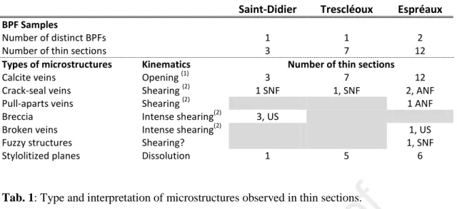
Saint-Didier Trescléoux Espréaux
BPF Samples
Number of distinct BPFs 1 1 2
Number of thin sections 3 7 12
Types of microstructures Kinematics Number of thin sections
Calcite veins Opening (1) 3 7 12
Crack-seal veins Shearing (2) 1 SNF 1, SNF 2, ANF
Pull-aparts veins Shearing (2) 1 ANF
Breccia Intense shearing(2) 3, US
Broken veins Intense shearing(2) 1, US
Fuzzy structures Shearing? 1, SNF
Stylolitized planes Dissolution 1 5 6
571 572
Tab. 1: Type and interpretation of microstructures observed in thin sections.
573
Four bedding-parallel faults (BPFs) were targeted in Espréaux, only two of them were successfully 574
retrieved. The numbers of thin sections showing each microstructure type is indicated in column for 575
each site. (1): Opening indicates an opening movement perpendicular to the BPF. (2): SNF and ANF 576
denote shearing (i.e., sliding) with a shear sense that is synthetic (SNF) or antithetic (ANF) with the 577
neighboring normal faults, i.e., movement in the same oropposite direction as that of the hanging wall 578
movement of the normal faults, respectively. US: shearing with unknown sense. 579
580
Fig. 1: Simplified geological map of the North West region of the Southeast Basin of France
581
(modified from Roche et al. (2014)) and tectonic calendar of the basin. Tectonic events are based on 582
analyses from Constantin et al. (2012), Lamarche et al. (2012),Homberg et al. (2013) and references
583
therein. Light grey and dark grey indicate extensional and compressive deformation phases, 584
respectively. The ages of the formations hosting the bedding-parallel faults (BPFs) are indicated by a 585
black arrow. The BPFs are located in Saint-Didier, Trescléoux and Espréaux sites. 586
587
Fig. 2: Context of bedding-parallel faults (BPFs) and sampling in Trescléoux (a), Espréaux (b) and
588
Saint-Didier (c). Normal faults (NF), offsetting the limestone and clay layers, and the bedding-parallel 589
faults (BPFs) are indicated. The limestone and clay layers are represented in light and dark grey, 590
respectively. The numbering indicates the location of the BPF sampling for the thin sections. 591
Examples of details of sampling are presented in the right panel. 592
593
Fig. 3: Stereographic projections (lower-hemisphere, equal-area projection) for the Saint-Didier site
594
(a), the Trescléoux site (b) and the Espréaux site (c). Data for the bedding-parallel faults (BPFs), the 595
normal faults and the strike-slip faults are back-tilted using the average tilting of the bedding. Solid 596
circles: fracture planes. Small black dots and arows: slickenlines. n: the number of data. Stars with 5, 597
4, 3 branches: maximal (σ1), intermediate(σ2), and minimal (σ3) principal stress. Divergent and 598
convergent arrows: directions of the extension (σ3) and compression (σ1). Small blue and red dots: 599
slikenlines on the BPFs that are coherent with the direction of extension (blue) and the direction of 600
compression (red) found using the normal faults and the strike slip faults, respectively. 601
602 603
Fig. 4: Thin sections of bedding-parallel faults (BPFs). (a) and (b): Saint-Didier; (c): Trescléoux; (d)
604
and (e): Espréaux. (a-e). Different microstructures are observed. C.V.: Calcite vein; Cl.: Clays (wall 605
rock); C.S.: Crack-seal vein; S.V.: Satellite vein; St.: Stylolite; Br.: Breccia; Cav.: Cavity. Location of 606
details illustrated in Figures 5 and 6. So: Bedding. 607
608
Fig. 5: Details of microstructures within bedding-parallel faults (BPFs). (a) Elongate blocky crystal
609
morphology in Saint Didier. (b) Shallow dipping veinlets in crack-seal veins indicating a top-to-the-610
west movement in Saint Didier. West is to the right. (c) Stylolite in calcite veins in Espréaux in optics 611
and cathodoluminescence. (d) Supperposed crack-seal veins in Espréaux. (e) Pull-appart veins in 612
Espréaux. (a-e) C.V.: Calcite vein; Cl.: Clays (wall rock); C.S.: Crack-seal vein; S.V.: Satellite vein; 613
St.: Stylolite. So: Bedding. 614
615 616
Fig. 6: Details of the microstructures in transmitted light and cathodoluminescence. (a) and (b): Saint
617
Didier (c-e): Trescléoux; (f) and (g): Espréaux. (a) Bedding veins and clays in wall rock display a dark 618
orange colour. (b) Breccia with a brighter orange than the calcite forming initially the BPF, indicating 619
different fluid generations. (c) Caclite vein and crack-seal veins. (d) Cavities infiling with various 620
fluids. (e) Calcite veins and stylolites. (g) Pull-apart veins. (a-f) C.V.: Calcite vein; C.S.: Crack-seal 621
vein; S.V.: Satellite vein; St.: Stylolite; Br.: Breccia; Cav.: Cavity. So: Bedding. 622
623
Fig. 7: (a) Complex zone of shearing in Espréaux showing angular fragments of calcite veins in a
624
clay-rich matrix. (a) General view. (b) Detail view. (c) Model for the formation of the microstructures 625
in (a) with imbrication. Shear movement of the clay in a shear zone generates failure, imbrication and 626
rotation of the calcite vein fragments. (d) Alternative model for the formation of the microstructures in 627
(a) with rotations and fragmentation of the BPF. (e) Examples of complex microstructures observed at 628
Espréaux. (f) Detail of echelon fuzzy structures and crack-seals. (a-f) C.V.: Calcite vein; Cl.: Wall 629
rock; C.S.: Crack-seal vein; S.V.: Satellite vein; St.: Stylolite; S.Z.: shear zone; F.V.:Fuzzy vein. So: 630
Bedding. 631
632
Fig. 8: Models for bedding-parallel fault history. In model 1, bedding-parralel faults (BPFs) are
633
monophased and all microstructures formed during the same tectonic event. In models 2 and 3, BPFs 634
are polyphase structures and were active during successive deformational events of the basin. In model 635
2, BPFs first slipped during the Oligocene extensional tectonics and were later reactivated during the 636
alpine inversion. In model 3, the BPFs initiated as opening fracture and were reactivated during all 637
subsequent tectonic events. Time uncertainrty for opening and pressure solution is indicated by grey 638
arrow. Each model reflects the successive movements along the BPFs deduced from microstructures 639
and outcrop observations: shearing (blue during extensional tectonics and red during compressional 640
tectonics) and opening normal to bedding. See text for more details and mechanical implication. 641
Model 1 does not apply for the studied BPFs (expect eventually in Saint-Didier site), but may 642
represent other example of BPFs. Exemples from this study support a long-lived history of BPFs. 643
644
Fig. 9: Cartoons illustrating two potential contexts of formation of bedding-parralel faults (BPFs). (a)
645
A segmented BPF formed due to flexural slip mechanism to accommodate bed-parallel slip. Slip is 646
partitioned along different segments of the BPF and normal faults occur in the releasing steps (e.g., 647
Pedrera et al., 2012; Delogkos et al., 2018). Arrows: shear sense. (b) Bi-modal faulting in multilayer
rocks. Failure follows the Andersonian mode in the limestones (high dipping normal faults are 649
formed) whereas it does not in the clays (BFPs are formed). These two types of faults later propagate 650
and connect each other. Convergent and divergente arrows: compression and extension. 651
Institut des Sciences de la Terre Paris – ISTeP UMR 7193 CNRS-UPMC
4 place Jussieu - Case 129 - 75252 Paris Cedex 05
catherine.homberg@sorbonne-universite.fr Tél. 33-1 44 27 52 74
www.istep.upmc.fr Paris, 6th July 2020
Ref: SG_2019_403
Journal: Journal of Structural Geology
The authors declare that they have no known competing financial interests or personal relationships that could have appeared to influence the work reported in this paper.
They have seen and approved the final version of the manuscript being submitted. They warrant that the article is the authors' original work, hasn't received prior publication and isn't under consideration for publication elsewhere.