Publisher’s version / Version de l'éditeur:
Vous avez des questions? Nous pouvons vous aider. Pour communiquer directement avec un auteur, consultez la
première page de la revue dans laquelle son article a été publié afin de trouver ses coordonnées. Si vous n’arrivez pas à les repérer, communiquez avec nous à PublicationsArchive-ArchivesPublications@nrc-cnrc.gc.ca.
Questions? Contact the NRC Publications Archive team at
PublicationsArchive-ArchivesPublications@nrc-cnrc.gc.ca. If you wish to email the authors directly, please see the first page of the publication for their contact information.
https://publications-cnrc.canada.ca/fra/droits
L’accès à ce site Web et l’utilisation de son contenu sont assujettis aux conditions présentées dans le site
LISEZ CES CONDITIONS ATTENTIVEMENT AVANT D’UTILISER CE SITE WEB.
Student Report (National Research Council of Canada. Institute for Ocean Technology); no. SR-2006-13, 2006
READ THESE TERMS AND CONDITIONS CAREFULLY BEFORE USING THIS WEBSITE.
https://nrc-publications.canada.ca/eng/copyright
NRC Publications Archive Record / Notice des Archives des publications du CNRC :
https://nrc-publications.canada.ca/eng/view/object/?id=b7ce766c-c4d4-459d-b9b3-7938cb9b9b2a https://publications-cnrc.canada.ca/fra/voir/objet/?id=b7ce766c-c4d4-459d-b9b3-7938cb9b9b2a
Archives des publications du CNRC
For the publisher’s version, please access the DOI link below./ Pour consulter la version de l’éditeur, utilisez le lien DOI ci-dessous.
https://doi.org/10.4224/8895451
Access and use of this website and the material on it are subject to the Terms and Conditions set forth at Design of a second generation articulated leg for the GAVIA underwater vehicle
REPORT NUMBER SR-2006-13 NRC REPORT NUMBER --- DATE April 2006 REPORT SECURITY CLASSIFICATION
Unclassified
DISTRIBUTION Unlimited TITLE
DESIGN OF A SECOND GENERATION ARTICULATED LEG FOR THE GAVIA UNDERWATER VEHICLE
AUTHOR(S) Steven Williams
CORPORATE AUTHOR(S)/PERFORMING AGENCY(S)
National Research Council, Institute for Ocean Technology (NRC-IOT) PUBLICATION
---
SPONSORING AGENCY(S)
National Research Council, Institute for Ocean Technology (NRC-IOT) IMD PROJECT NUMBER
42_2091_10
NRC FILE NUMBER ---
KEY WORDS
Gavia, articulated leg, autonomous underwater vehicle, AUV PAGES vi, 21 App. A,B FIGS 16 TABLES 0 SUMMARY
This report details the design of a folding leg mechanism used by the Gavia for pipeline inspection. There is a brief introduction to the Gavia and the previous leg system. A list of requirements and challenges is then presented. The theoretical design is given and
described. The encoder system and wheel choice is then explained. A force analysis is completed and a virtual model of the leg, created in MatLAB, is displayed. Finally, a conclusion is given with suggestions for future work.
ADDRESS National Research Council Institute for Ocean Technology Arctic Avenue, P. O. Box 12093 St. John's, NL A1B 3T5
Institute for Ocean Institut des technologies
Technology océaniques
DESIGN OF A SECOND GENERATION ARTICULATED LEG FOR THE
GAVIA UNDERWATER VEHICLE
SR-2006-13
Steven Williams
Table of Contents
1.0 Introduction 1 2.0 Design Challenges 3 3.0 Leg Design 4 3.1 Link Design 4 3.2 Hinge Design 53.3 Joints and Connections 6 3.4 Slider Mechanism 6
4.0 Wheel and Encoder 8
5.0 Force Analysis 10
5.1 Bending Moment Calculations 10 5.2 Force Analysis Calculations 12
6.0 MATLAB® Code and Analysis 15
6.1 Force Analysis 15 6.2 Virtual Reality / Simulink® Model of Articulated Leg 16
7.0 Conclusions and Future Work 21
8.0 References 22
Appendix A – CAD Drawings Appendix B - MATLAB® Code
List of Figures
Figure 1: Gavia AUV in modular sections 1 Figure 2: Leg development in “GeoGebra” 4 Figure 3: Leg with unbalanced forces 5 Figure 4: Leg with fork that distributes force evenly 5 Figure 5: Bushing for wheel that will allow it to rotate 6 Figure 6: Leg with attached sliders and motor 7 Figure 7: Top linkage with encoder (left), Cross section of wheel and encoder
(right) 8
Figure 8: Bending moment diagram using a bar supported on both ends 10 Figure 9: Geogebra model of leg and the forces at each joint 13 Figure 10: Slider level with the base (left), slider dropped down 2.5 cm (right) 14 Figure 11: Force analysis of leg as it folds down 15 Figure 12: Leg development in ‘V-Realm’ 17 Figure 13: System of legs to be placed on Gavia 18 Figure 14: Simulink® model of Gavia 19 Figure 15: Gavia with legs extended 20 Figure 16: Gavia with legs folded 20
List of Abbreviations and Symbols
AUV……….. Autonomous Underwater Vehicle ABS………Acrylonitrile Butadiene Styrene CAD………...Computer Aided DesignLi………Lithium
NRC-IOT………...National Research Council Institute for Ocean Technology PVC………Polyvinyl Chloride
1.0 Introduction
The Gavia is an AUV (autonomous underwater vehicle) designed by Hafmynd Ltd., which is located in Iceland. This AUV has the ability to accept a very large variety of payloads, which extend the vehicle along its central communication bus.
It uses a variety of modules to move and navigate in the water. These modules include the nosepiece, Li-ion battery module, communications system, and a propulsion and steering module.
As the Gavia is modular, custom payloads can be created for an endless number of applications.
Figure 1: Gavia AUV in modular sections
The Institute for Ocean Technology and the Institute for Research in Construction are interested in using the Gavia to inspect the insides of freshwater pipelines. As the Gavia can be modified with ease, it provides the perfect test bed for new sensor and navigation systems as it applies to profiling the inside of a pipe.
It has been decided to profile the pipe using a multibeam sonar fitted to the outside of the vehicle. A system of legs will be used in order to hold the Gavia around the center of the pipe to allow for a useable sonar image.
A first generation of legs have been developed which can only provide force according to their spring coefficient. They are one solid piece made from PVC and they are mounted onto a ring that slips over the Gavia’s hull.
A second generation of legs must be designed that can fold into the vehicle and apply a variable force on the walls of the pipe. As well, these legs will be
outfitted with an encoder system that will allow the user to monitor the AUV’s position more closely.
2.0 Design Challenges
There are a number of challenges involved in designing the legs for the Gavia. Many of them relate to the physical space we have to work with.
The legs must be able to fold into the vehicle allowing it to be placed into the pipe. As well, they must be able to support the vehicle’s weight on land, as ideally the Gavia can roll on its folded legs.
The legs must be able to extend a minimum of 40 cm and support a 100 Newton force (10 times safety factor).
The wheels need to be modified to include an encoder ring and proper circuitry.
A linear slide must be found to allow the actuator to extend the leg. The slide must also be small enough to fit under the leg mechanism when it is folded down.
Tolerances for the wheel must be very exact to allow for very little lateral travel. In this way, the distance between the encoder and recorder will be less than 2 mm.
All electronics must be waterproofed without adding much to the weight or size of the system.
3.0 Leg Design
3.1 Link Design
The second-generation leg had to be able to extend to a height of 45 cm while fold into a height of about 5 cm. The required link lengths were developed using the software “GeoGebra”, developed by Markus Hohenwarter. Using the
dimensions developed, a model leg was developed and built using PVC.
Figure 2: Leg development in “GeoGebra”
Each wheel is supported with two linkages like the one above. However, there is only one upper linkage (as seen below). Initially the upper linkage’s base was just made wider to accommodate the width of the wheel. However, this led to an unequally distributed force and created a weak point.
Figure 3: Leg with unbalanced forces
It was decided that using a fork design would be much more practical and would make the leg only about one cm wider, as shown in Figure 4.
Figure 4: Leg with fork that distributes force evenly
The legs are made out of aluminum because of its strength, weight, surface finish, and its resistance to corrosion.
3.2 Hinge Design
A hinge had to be developed to hold the leg in place and mount it to the Gavia. The distance between the 2 base legs is 5 by 5 cm. The hinge is secured with two screws in its base. This piece is also machined in aluminum.
3.3 Joints and Connections
Shoulder bolts are used in between the legs for motion. Four bolts have to be made with a 5cm unthreaded surface in order to accommodate the thicker third leg.
The joint between the wheel and the fork was designed to have no clearance issues with the leg when folding. A horizontal travel of one-tenth a millimeter had to be considered in order to allow the encoder to work correctly. To do this, a bushing is press fit into the wheel. Two separate rollers are then screwed into the bushing; see Figure 5. This allows the rollers to rotate in the fork without creating any connection points outside of the fork
Figure 5: Bushing for wheel that will allow it to rotate
3.4 Slider Mechanism
To move the leg, it was decided to use a linear actuator that would move horizontally at the base, attached to the leg by a slider link; see Figure 6. The motor is fixed and the link moves up and down the slider track.
A moving model of the leg was built in “GeoGebra” that could be rotated by moving the virtual sliding link. Ideally, the slider travel needs to be less than 5 cm so the slider must be placed as close to the base of the leg as possible.
However, this will increase the force required to raise the leg. It was decided to make the slider 10 cm long and place it 63 cm up on the base leg.
The 2 slider bars will be attached to a very small slider rail found on McMaster-Carr (item #’s 6725k9 and 6725k23). The sliders will be joined together and driven by a single actuator located under the center of the leg.
4.0 Wheel and Encoder
As the previous generation wheel was made of a solid rubber, a new wheel had to be found that would provide enough frictional force in water. It was decided to use a 10 cm diameter wheel by Coloson for the application.
In order to track the AUV’s position in the pipe, it was decided to use an encoder mechanism on the wheel. In this way, as the wheel rotates along the pipe, the sensor picks up signal from the magnetic strip in the encoder ring and the distance can be recorded.
Figure 7: Top linkage with encoder (left), Cross section of wheel and encoder (right)
In order for the sensor and encoder ring to work, there must be a maximum distance of 2 mm between them. For our application, it was desired to bring this distance to a maximum of 0.5 mm. To accommodate this, the lateral travel of the wheel was machined to a tenth of a millimeter.
CAD diagrams were developed in order to decide on a mounting mechanism for the encoder. It was decided to mount the encoder circuit on the inside of the top leg. The wheel was then put onto a lathe and machined so that the encoder ring would fit in over the wheel. The encoder is held in place using four M4 screws tapped into the wheel.
5.0 Force Analysis
5.1 Bending Moment Calculations
In order to calculate the size of actuator to power the leg, a force analysis was completed. The strength of the material was calculated as well as the bending moment. In order to simplify the system, the leg will be considered as a 29 cm bar with two fixed ends and a 100 N force pushing down at 75 mm from one end.
The tensile strength of a common aluminum (6060) was found to be 45 000 psi using a reference book.
Since:
1 Mpa = 145 psi
45 000 psi = 310 MPa
Therefore, 310 MPa is the maximum force we can apply on the beam.
To calculate the bending moment we will need to find the moment created on the beam:
Figure 8: Bending moment diagram using a bar supported on both ends
Moment about A = -(100)(75) + (210)(Rb) 7500 = 210Rb
Rb = 26.54 N
Ra + Rb = 100 N Ra = 73.46 N
The maximum bending moment is calculated by taking the moment around the point at which the 100 N force is applied. That is:
Mc = 73.46 N * 75 mm Mc = 5597.7 N mm
The maximum bending stress is calculated using the formula:
Z M = max σ where: M = bending moment Z = I/C = section modulus
C = distance from the neutral axis to the outer surface where maximum stress occurs
I = moment of inertia
The neutral axis is located at the geometric center of the bar and as the force is located on the outer surface of the bar, C = 9.525 mm.
The moment of inertia is calculated using the equation:
12 ³ h b I = ⋅ where: b = thickness of bar (mm)
h = width of bar (mm) 12 ³ ) 375 . 18 )( 1875 . 9 ( = I I = 4750.04 mm4 Therefore: 4 ^ 04 . 4750 ) 525 . 9 )( 7 . 5597 ( max mm mm mm N⋅ = σ max σ = 11.223 MPa
According to the tables provided by “Russel Metals Inc”, the stress required for breakage is 45 MPa. This will give us a safety factor of four, which is acceptable for this application as the maximum force applied to the leg will be about 10 Newton.
5.2 Force Analysis Calculations
As the aluminum legs should not bend, we can treat each leg as a rigid body and calculate the forces on the leg by summing the forces at each joint. This will allow us to calculate the force required by the linear actuator to lift the leg from its closed position with 100N of force on the wheel.
Figure 9: Geogebra model of leg and the forces at each joint
As seen in Figure 9, points 1 and 2 can be used to calculate F1, F2, F3 and F4. At point 1 there are two equations and two unknowns. F1 and F2 must be found using the equations for the sum of the forces in the x and y directions. From there we can now do the same at point 2, as F1 is known.
At link 3, a point analysis cannot be used as R is acting on the bar. This force creates a moment on the leg. As F2 and F4 are known, we can find R by summing the moments around the base. In turn, ‘F slide’ is simply the x component of R.
In order to calculate ‘F slide’ as the leg is extended, this calculation must be completed again and again as the leg changes position. In order to do this, a
MATLAB®code was written that could do this and graph the results (see Section 6.0).
It was also desirable to look at the force required if the sliding base was moved down 2.5 cm to allow for a smaller “F slide” force when the leg was closed. This is a result of R having a smaller x component when the slider is lowered; see Figure 10.
6.0 MATLAB
®Code and Analysis
6.1 Force Analysis
MATLAB®was used to graph the changes in force while the leg was folded. As the leg is moved, the instantaneous forces are calculated at each joint and
related to the overall force on the system in order to keep it static in that position.
In order to calculate these forces, it was required to find the angles between the linkages at each joint. All of these angles must be related back to one initial angle, which was chosen as the angle between the slider path and slider bar. All of these angles are then stored in a data structure and called on when needed in the force analysis. All calculated forces are stored in a separate structure where they can be compared and analyzed.
A set of simple graphs was generated to compare the forces on the motor when the slider was moved; see Figure 11.
Force ‘A’ is found when the slider is level with the base of the leg and Force ‘B’ is defined as the motor force when the slider is lowered to allow for a larger folded angle.
It can be seen that there is a large difference in the maximum force when then leg is closed. As well, when the slider is lowered there is a much more
continuous force with a smaller slope.
As this test is accommodating a 100 N force at the wheel and the real world force will be around 10 N, position ‘B’ will provide the best control of the leg and a smaller motor will be needed. Moving the slider down 2.5 cm will only increase the motor travel by about 20 mm. This will put the actuator travel at about 63 mm, which can easily be obtained in a small motor.
6.2 Virtual Reality / Simulink® Model of Articulated Leg
It was desired to develop a virtual model of the leg for visual representation of how the final leg would fold into the vehicle. This was done in MATLAB®using the virtual reality toolbar in Simulink®.
Initially, the AutoCAD drawing file of the leg had to be converted into a vrml file. This was done using a trial of the tool “VrmlExport for AutoCAD” by Xanadu.
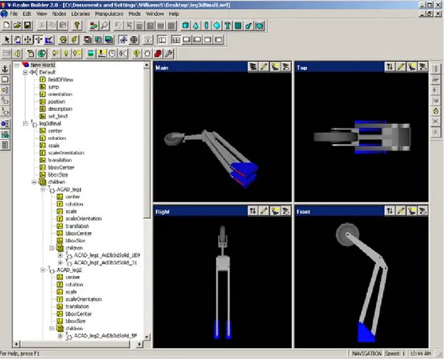
Once a vrml file was created, it could be edited in “V Realm Builder” from the MATLAB®package.
Figure 12: Leg development in ‘V-Realm’
In “V Realm Builder”, all objects are located on the left hand side with sub-objects labeled as children; see Figure 12. For our application the center of gravity was relocated to the rotation point on each link. This allows the linkages to rotate around the proper joint when a signal is applied though Simulink®.
In order to rotate the link that holds the wheel, translation and rotation had to be accommodated for. In order to do this, the wheel and fork were given a center point at the end of that linkage as sub-systems, or children. The global system was then given a common center point to the entire leg located at the base of the system. In this way, the upper linkage can rotate around two points
Once the signals were developed in Simulink® to control one leg, a more
advanced model was developed that could control multiple legs at once. A code was developed to rotate four legs that would be placed on the Gavia; see Figure 13.
Figure 13: System of legs to be placed on Gavia
Finally a complete model was developed that included the Gavia vehicle with two sets of legs and the multibeam sonar that will profile the inner wall of the pipeline.
Figure 14: Simulink® model of Gavia
In the Simulink® code, each signal controls a joint on the leg. The subsystems break up the coordinate system and tell the model which axis it should use in rotation. The signal is then fed into the appropriate input on the model; see Figure 14.
The animation was captured to a movie file that shows the legs folding down from an open position; see Figures 15 and 16 which are snapshots from this movie.
Figure 15: Gavia with legs extended
Figure 16: Gavia with legs folded
It should be noted that when the Gavia is used for the pipeline inspection the communications tower will be removed and possibly the acoustic modem as well.
7.0 Conclusions and Future Work
The goal of this project is to develop a set of new modules for the Gavia vehicle that will allow it to inspect the inside of freshwater pipelines. It will use a system of legs and wheels with integrated encoders and brakes to control its position to allow for accurate profiling of the inner wall of the pipeline.
Currently, a prototype leg has been submitted to the design team and is awaiting fabrication. Once this model is completed it will be valuable to use the existing actuator we own for the ‘Flexfin’ to test the leg movement as well as the force required.
A mounting mechanism must be developed for the Gavia vehicle to
accommodate the folded wheels and the actuators that will drive each leg. As well, waterproofing the encoder and actuator will be a concern.
Finally, a wheel with a built in inverted motor by Maxon will be used as a brake system to allow the vehicle to hold its position in the pipe. These motors were obtained this semester but need to be tested and implemented into three of the wheels.
1. GAVIA, Geat Northern Diver
http://www.gavia.is.
2. Griffiths, Gwyn. “Technology and Applications of Autonomous Underwater Vehicles”, Taylor and Francis, New York, 2003.
3. Hewitt, G. “Gavia as a Pipeline Inspection Vehicle”, CISTI-IOT Report SR-2005-30.
4. Hibbeler, RC. “Engineering Mechanics Statics and Dynamics” tenth edition,
Prentice Hall, New Jersey, 2004.
5. Kaufman, J.G. “Fracture Resistance of Aluminum Alloys”, Aluminum Association and ASM International, US, 2001. 6. Russel, C. “Reference Book 84-17”,
Russel Metals Inc. Canada,1991. 7. Strength of Materials – Engineers Edge
http://www.engineersedge.com/strength_of_materials.htm. 8. Zubaly, Robert. “Applied Naval Architecture”,
Cornell Maritime Press, Maryland, 1996.