HAL Id: hal-03109853
https://hal.archives-ouvertes.fr/hal-03109853
Submitted on 14 Jan 2021
HAL is a multi-disciplinary open access
archive for the deposit and dissemination of sci-entific research documents, whether they are pub-lished or not. The documents may come from teaching and research institutions in France or abroad, or from public or private research centers.
L’archive ouverte pluridisciplinaire HAL, est destinée au dépôt et à la diffusion de documents scientifiques de niveau recherche, publiés ou non, émanant des établissements d’enseignement et de recherche français ou étrangers, des laboratoires publics ou privés.
micro-regenerators
Arkadii Sochinskii, Damien Colombet, Manuel Medrano Muñoz, Frederic
Ayela, Nicolas Luchier
To cite this version:
Arkadii Sochinskii, Damien Colombet, Manuel Medrano Muñoz, Frederic Ayela, Nicolas Luchier. Pressure losses at moderate Reynolds numbers in diamond-shaped cylinders arrays: application to micro-regenerators. Journal of Fluids Engineering, American Society of Mechanical Engineers, 2021. �hal-03109853�
application to micro-regenerators
A. SochinskiiPhD Student
Univ. Grenoble Alpes CNRS, Grenoble INP, LEGI
Grenoble, France, 38000 present adress: Universit ´e c ˆote d’azur
D. Colombet
Assistant professor
Univ. Grenoble Alpes CNRS, Grenoble INP, LEGI
Grenoble, France, 38000
Email: damien.colombet@univ-grenoble-alpes.fr
M. Medrano Mu ˜noz
Assistant professor
Univ. Grenoble Alpes CEA, IRIG, DSBT Grenoble, France, 38000
F. Ayela
Professor
Univ. Grenoble Alpes CNRS, Grenoble INP, LEGI
Grenoble, France, 38000
N. Luchier
Senior researcher
CEA, Univ. Grenoble Alpes, IRIG, DSBT Grenoble, France, 38000
ABSTRACT
Cylinders with an elliptical, oblong, lenticular, sinus or diamond transveral shape are very interesting geometries for the design of compact heat exchangers. This work investi-gates the role of the porosity and of the apex angle of diamond-shaped cylinders networks on the pressure losses, at moderate Reynolds numbers, inside micro heat regenerators. The design of the geometry under test has been chosen so that the cross section of the flow remains almost constant along the path of the flow between cylinders. Experiments have been performed at 1ď Re ď 30 and a porosity range 0.40 ă ε ă 0.90 for an apex an-gle of α“ 33˝. Numerical simulations have been conducted using the same Reynolds and
porosity ranges but varying the apex angle 33˝ ď α ď 90˝. Experimental measurements and dimensional analysis have shown that the friction factor can be affected by the poros-ity. 2D numerical simulations confirmed that the friction factor increases with the porosity but also with the apex angle. An analysis at the scale of a channel flanked by adjacent cylinders has provided a original correlation able to describe easily the evolution of the Poiseuille number and the collective effects on the drag coefficient as a function of α and ε. Such a diamond-shaped design is found to induce much lower Poiseuille numbers than those expected from conventional stacked spheres, woven wires and circular cylinders ar-rays. The findings of this study can help for better understanding the optimization of low pressure drop regenerators and how to reduce associated hydraulic power.
HIGHLIGHTS
Poiseuille numbers are globally much lower than conventional arrays. Poiseuille numbers increase with the porosity and with the apex angle. The variation of the tortuosity explains Poiseuille variations with the porosity.
A new simple correlation is proposed to describe both Poiseuille numbers and drag.
INTRODUCTION
In the frame of process intensification, miniaturisation leads to the design of thermally efficient heat exchangers having the lowest energy consumption. The hydraulic power required to generate fluid flow is the product of the volumetric flow rate by the inlet/outlet pressure drop. For a given exchanger design it is thus important to not only evaluate heat transfer efficiency or thermally-optimal arrangement, but also to characterize the corresponding pressure losses. , For the sake of simplicity, references in the literature are mostly related to cylinder shaped arrays also called ’tube bundle’ or ’tube bank’ [1, 2, 3, 4, 5, 6].
By designing compact cylinders array heat exchangers, the main solution to enhance heat flux per volume unit is to increase the total exchange area. This is usually achieved either by decreasing the cylinders size and increasing their number per volume unit, or by changing the
cylinders aspect ratio and their shape. The main shapes studied for heat exchangers with non-circular cylinders arrays are elliptical or oblong [7, 8, 9], rectangle or square [10, 11, 12, 13, 14], lenticular [15] but also, in more recent studies, sinus and diamond [16, 17, 18, 19, 20].
For in-line or staggered arrangement of square or diamond-shaped cylinders arrays with an apex angle of α“ 90˝, heat transfer or pressure drop were characterized by Chyu et al. [17], Tanda
[18] or Jeng [19]. Chyu et al. [17] found experimentally that staggered matrix of squared shaped cylinders exhibits a higher transfer rate than a staggered diamond shaped array, which exhibits an higher transfer rate than a staggered circular cylinders array. Globally staggered arrangements are found to generate higher heat transfer rates and pressure losses than in-line arrangements. The transfer was studied using a naphthalen sublimation technique. In an air flow through diamond-shaped cylinders arrays, Tanda [18] has quantified in 2D mass transfer rate and temperature distribution for staggered and in-line arrangement using liquid crystal thermography and image processing. According to the authors, at the same hydraulic powers, diamond-shaped cylinders arrays can be up to 1.65 more efficient than an empty channel. Flow and heat transfer in a compact diamond-shaped cylinder exchanger was also studied experimentally by Rasouli et al. [21] using liquid nitrogen for thermal management applications in cryo-adsorbent hydrogen storage systems. The authors observed an increase of the friction factor with the Reynolds number above Re ą 580 ´ 650, because of flow flapping behind the cylinders. The thermal efficiency was also investigated experimentally by Jeng [19] for the case of in-line array of diamond-shaped cylinders using a transient method for measuring the heat transfer coefficient. The author has concluded that for a given hydraulic power it is possible to find an optimal distance between cylinders to maximize heat transfer.
It is important to stress that, in the literature, usually named diamond-shaped cylinders arrays are in fact 45˝ inclined square-shaped cylinders (i.e. diamond shape with an apex angle of α “
90˝). The effect of varying the apex angle (or cylinder section aspect ratio) is not systematically considered.
Heat exchangers with a diamond shape having an apex angle equal or lower to 90˝ were studied for electronic cooling applications in space industry [16, 22, 20]. Pressure drop
coeffi-cients in such geometries with an apex angle of 45 or 90˝ and a porosity of 65% were charac-terised experimentally and numerically by Sparrow & Grannis [16] for the Reynolds number range 20 ă Re ă 2700, in order to give correlations to assist dimensioning of an air/air heat exchanger for a space shuttle. That question was in the same time studied numerically in a companion paper of Grannis & Sparrow [22] using a finite-element method. The authors have simulated a periodic domain to investigate the flow and the pressure drop in similar diamond-shaped cylinder staggered arrangements. For α“ 45˝, the authors propose two correlations of the friction factor and suggest that the Poiseuille number is quite constant for the range 0.22ď ε ď 0.70 for an arrangement cor-responding to an equilateral triangular pattern (P o« 108) and to a regular staggered arrangement (P o « 97). For α “ 90˝ and same arrangements, the authors propose correlations considering a singular pressure drop per row of cylinders. In this reference, the authors admitted that it is very difficult to collapse results with α“ 45˝ and α“ 90˝under a common description.
Later, diamond-shaped cylinder networks were also investigated by Vanapalli et al. [20] for their use as a micro-heat exchanger for the cryocooling of satellite electronic. For laminar flows at moderate Reynolds numbers (50ď Re ď 500) and apex angle of α “ 37.15˝, [20] found exper-imentally that a diamond-shaped cylinder matrix generates a higher pressure drop than circular, square, elliptical or sinus shapes.
For a turbulent flow regime and downstream an array of diamond-shaped cylinders, the jet for-mation with a specific flapping instability has been observed at the outlet of a liquid flow emerging into air [23, 24]. For such a flow, by using numerical simulations and experimental measurements, Hirasawa et al. [25] proposed correlations to describe the pressure drop and heat transfer in an array of diamond-shaped cylinders with an apex angle of α“ 30˝.
In micro-fluidics, the diamond-shaped cylinders arrays have also been investigated for liquid phase chromatography applications [26, 27, 28]. This geometry seems to offer better chromato-graphic performances than circular or ellipse cylinders arrays. Finally, porous diamond-shaped cylinders are also expected to be interesting for biological filtering processes [29]. As a result, various applications could benefit from the knowledge of the pressure drop in an array of diamond-shaped cylinders.
In the literature, the pressure losses in cylinders arrays depends on the compactness of the heat exchanger. This is usually quantified by considering the exchanger porosity that is the ratio between the volume occupied by the fluid to the total volume of the exchanger. Pressure losses in non compact heat exchangers with cylinders arrays at high and moderate porosity are presented as the sum of singular pressure losses controlled by the number of cylinder rows in the array, using the maximal velocity in the network for the calculation of the Reynolds number [1, 3, 16, 8, 5]. This approach can be justified for a dilute array of cylinders, where a row of cylinders can be considered as a singularity. For more compact exchanger, decreasing the porosity make the exchanger close to a porous media and pressure losses can be described as a linear pressure drop considering the friction of the flow on the walls. This approach consists in using the Darcy-Weisbach coefficient is typically the one employed for compact heat exchangers [30, 22, 12, 18, 13, 20, 19, 14] using a mean velocity for the Reynolds calculation. In addition, a large number of correlations exists to describe the pressure drop in cylinders arrays. Usually it is found from numerical or experimental works that the friction factor is not only controlled by the Reynolds number but also monitored by the lateral or longitudinal dimensionless distances and the arrangement (in-line or staggered [31]). Different comparative studies have pointed out the fact that available correlations in the literature are not able to predict experimental pressure drop accurately (see [32, 33] and [34]). As a matter of fact, even if the literature on that subject is large, the understanding of flow behaviour and associated pressure losses in cylinders arrays remains a question of interest. Moreover, to our knowledge, for diamond-shaped cylinder arrays, no available correlation able to predict pressure losses for a wide range of porosity and apex angle has been published.
The paper is organized as follows. First, the geometrical parameters of the exchanger under investigation and its micro-fabrication are presented. Then, the parameters used to characterize the flow are introduced. After that, the experimental investigations performed are detailed for diamond-shaped cylinders arrays with an apex angle of α“ 33˝ and a porosity of 0.45ď ε ď 0.78.
Finally, a numerical investigation is achieved for the same geometry and porosity range but with a larger range of apex angle 33˝ ď α ď 90˝. In those two last sections, preliminary validation tests are performed and results are compared to the literature.
The main novelity of this work is to extend the investigations of Sparrow & Grannis ([16, 22] which were limited to a single porosity (ε“ 65% and α “ 45 or 90˝) at a much larger range on the
porosity ε but also on the apex angle α. The second asset of this work is to consider a specific staggered arrangement intended to maintain a constant flow cross section, that is known to be an important parameter to minimize pressure drops as shown previously by Ruhlich & Quack [15] thanks to a numerical study on the optimisation of regenerators design. Indeed, if the flow cross section varies continuously and significantly, one important contribution to the pressure losses is the flow acceleration and deceleration along its path. In this work, a geometrical constraint is im-posed to follow this principle and keep the flow cross section quite constant. The third advantage of this work is to propose to use three complementary approaches (experiments, numerical simu-lations, dimensional analysis) to bring new findings on that topic. Finally, compared to many other previous works using random arrays of spheres or wires as a regenerator, as already performed by a few research teams before (see for example [20]), the last originality of this study is to control perfectly the geometry of the regenerators thanks to the developpment of MEMS techniques.
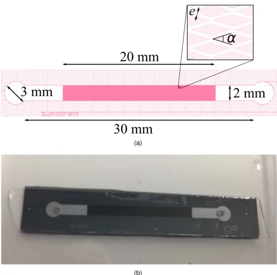
GEOMETRICAL PARAMETERS
The samples used in our study consist of straight channels with a rectangular cross section and with micro structures inside, that act as a porous media. Figure 1 shows the layout and a picture of one of our sample. The width and the length of the main channel are the same for all the samples. The circular tanks at the ends are used to connect the inlet and outlet easily. In our experiments, the porous area consists of a micro-size solid cylinders matrix located in the center of the channel. These cylinders are diamond-shaped with an apex angle α equals to 33 degrees (see Fig, 1a). This angle corresponds to an aspect ratio of 0.30 that was identified in a previous work to be a potential compromise between efficient heat transfer and moderate pressure losses [15]. In the numerical investigations, the apex angle has been changed to estimate the influence of the apex angle on the pressure drop.
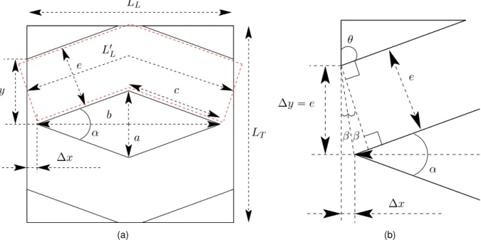
The present work focuses on the case of a periodic staggered arrangement of diamond shaped cylinders as presented in Fig. 2 with a width ’a’ and length ’b’ that depends on the apex angle
α “ 2 ˆ atanpa{bq. The parameter c “arpa{2q2
` pb{2q2
s is the length of one of the cylinder face so that for one cylinder the wetted surface in contact with the fluid is 4cH, where H is the cylinder height. ’e’ is the distance between two cylinders faces, but it can also be presented as the width of the channel formed between the diamond-shaped cylinders. ∆x stands for the distance between the front (resp. rear) apex angle and the inlet (resp. outlet) of the chosen periodic domain. ∆y corresponds to the distance between the top (resp. bottom) equator angle and the top (resp. bottom) side of the periodic domain. LL“ b ` 2∆x and LT “ a ` 2∆y are respectively the length
and width of the periodic pattern.
As explained in the introduction, to minimize the singular pressure losses due to fluid accel-eration/deceleration, heat exchanger geometries having a quasi constant cross section between matrix columns have been investigated in the present work. To fulfill this condition, the geometrical constraint e“ ∆y has been imposed to the studied gemotries. From Fig. 2b, with this constraint, it can be shown that this imposes π “ 2β ` π{2 ` θ and π “ π{2 ` θ ` α{2 (upper triangle) so that β “ α{4 and then ∆x “ e tanpα{4q. Consequently, the size of a periodic domain for such geometries is simply LL“ b ` 2e tanpα{4q with LT “ a ` 2e.
It is now possible to define the exchanger porosity (or volume fraction of fluid) as a function of the geometrical parameters as follows
ε“ Vf luid{Vtotal“ 1 ´
Vcylinders
Vtotal
“ 1 ´ ab
pb ` 2e tanpα{4qqpa ` 2eq (1)
with Vtotal“ Vf luid` Vcylinders “ LLLTH “ pb ` 2∆xqpa ` 2∆yqH “ pb ` 2e tanpα{4qqpa ` 2eqH
and Vcylinders“ 2pab{2qH “ abH.
According to the porous media approach, the hydraulic diameter of the heat exchanger matrix is defined as follow
Dh “
4εVtotal
Acont` AWcont
(2)
where the wetted surface in contact with the column is Acont “ 8cH. In our experiments the
wetted surface in contact with the top an bottom channel walls is AW
cont “ 2LLLTεwhile for 2D
simulations one has AWcont “ 0. In practice, experimental samples were designed by varying the
porosity between 0.4 and 0.8 with α« 33˝ for a given cylinder distance ’e’ (10´ 20 ´ 40 µm).
For a fully 2D geometry, where H is much larger than all other lengths as in numerical sim-ulations (Acont ąą AWcont), by noticing that 1´ ε “ ab{Vtotal, it is easy to show that the hydraulic
diameter can be simplified into a function of the cylinder width ’a’, the apex angle and the proposity
Dh “ 4εVtotal Acont “ ˆ ε 1´ ε ˙ a cospα{2q (3)
It should be noticed that from a numerical perspective the periodic domain is not the smallest periodic pattern since an additional axial symmetry can be considered along the line passing at the two front and rear apex angles. The choice of the current periodic domain was initially motivated to enable further study of side wall boundary effects in the channel (complete adherence condition on one side). But this was finally out of the scope of the present study.
DEVICE MICRO-FABRICATION
The fabrication of the device is based on MEMS techniques. First, the pattern of the channel is transferred from a chromium mask onto a 140´ 400 µm thick silicon substrate by lithographical steps (spin coating of a S1818 positive photoresist and UV irradiation of 30 mJ{cm2
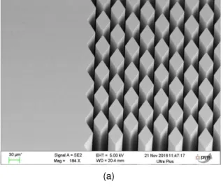
. ) Then, the pattern of the exchanger with the cylinders matrix is etched using a customized Bosch deep reactive ion etching process (DRIE). As shown in Fig. 3, by controlling the number of cycles, pas-sivation coating, etching and cooling steps durations, a special recipe was established to provide
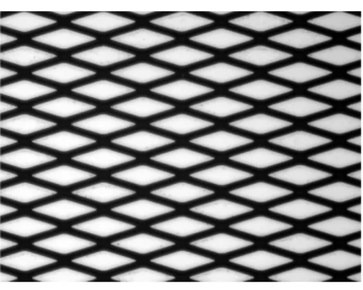
structures with a high aspect ratio (H{a) and vertical walls. An overview of the sample matrix, observed with an optical microscope with the same magnification factor of ˆ20, is presented in Fig. 4. As shown in this figure, for a given cylinder spacing ’e’ the increase of the porosity induces a decrease of the column sizes (’a’,’b’).
Finally, the silicon channel is anodically bonded to a Pyrex 1 mm thick cap that has been preliminary drilled at its extremities for inlet and outlet pipe connexions (see Fig. 1). The sealing between the Pyrex cap and the inlet/outlet holes is insured by using stainless steel slices equipped with vitton O-rings.
The depth of the channel depends on the number of etching cycles. Two kinds of samples have been micro-machined: for the first one the etched depth H is lower than the silicon substrate thickness (100 ď H ď 190µm, silicon/Pyrex samples); while for the second one the silicon sub-strate, previously bonded to a second Pyrex cap, is etched through its entire thickness, making possible the production of transparent Pyrex/Silicon/Pyrex samples.
Dimensions after etching may be different from those of the original mask because of the un-desirable side wall etching effects. The real dimensions are determined by analysing a set of optical microscopy photographs. Using the gray level histogram, a threshold is manually adjusted on the gray level images from the optical microscope to binarise the image such that diamond-shaped cylinders are put in white while background is in black (empty areas). Then, to accurately characterize the geometry of the etched samples, a conventional images treatment is used for labelling detected objects and extract data statistics [35]. An example of image used for the mea-surements of the sample dimensions is presented in Fig. 4e. With this method, the ’bounding box’ gives the access to ’a’ and ’b’ values for one cylinder while vertical and horizontal distance between cylinders centroids give the measurements of the periodic pattern sizes LL “ b ` 2∆x
and LT “ a ` 2∆y. Finally, the arithmetic average of those measurements is considered and the
other parameters such as ’c’, ’e’, ’ε’ or Dh are then calculated using relations introduced in the
previous section.
The channel depth has been measured using two methods : in the first one, with a profilometer in an area of the channel without any cylinder (just before or after the porous area); in the second
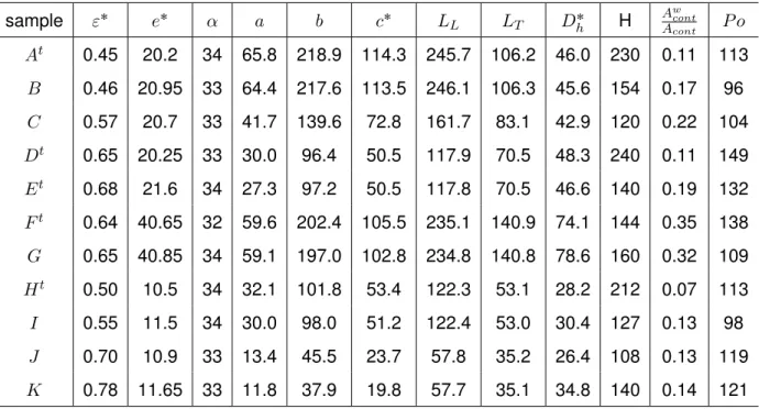
one, some samples of the batch are cut crosswise and the depth of the channel is measured by scanning electron microscopy (see Fig. 3, c). The etch depth inside the porous media have been also checked by focusing consecutively on the top and on the bottom of cylinders with an optical microscope equipped with a vernier. Table 1 lists the geometric parameters of the 11 samples micro-fabricated for this work.
FLOW CHARACTERISATION
The flow and pressure drop have been investigated by varying the Reynolds number Re of the exchanger, calculated as
Re“ ρ U Dh
µ (4)
The pressure drop between the inlet and outlet of the flow is then quantified by calculating the Darcy-Weisbach coefficient
f “ Dh L
∆P
1{2ρU2 ∆P “ Pin´ Pout (5)
Lis the exchanger length (L“ LLfor simulations), U is the average flow velocity calculated in
the experiment. This formulation based on the linear pressure drop is more adapted to compact heat exchangers than considering singular pressure drop per cylindere row (see for example [22]). Our results have been also analysed using the Poiseuille number defined as the product of the pressure drop coefficient with the Reynolds number P o“ f ˆ Re.
During our numerical simulations, the flow around a single cylinder inside the matrix has been also characterized by the corresponding drag coefficient. The drag coefficient is calculated from the drag forceFdby integrating the pressure and viscous stress τ on the cylinder surface
CD “ ||Fd|| App1{2qρU2 “ 1 App1{2qρU2 ˇ ˇ ˇ ˇ ˇ ˇ ˇ ˇ ż S p´p ¨ n ` τ ¨ nqdS ˇ ˇ ˇ ˇ ˇ ˇ ˇ ˇ (6)
with n the unit vector normal to the cylinder surface, Ap “ aH corresponds to the projected
surface area based on the product of the cylinder width with its height. The drag coefficient varia-tion is analysed with respect to the Reynolds number of the cylinder ReD characterizing the flow
at the scale of one cylinder and defined as follow
ReD “
ρ U a
µ (7)
EXPERIMENTAL INVESTIGATIONS Experimental setup
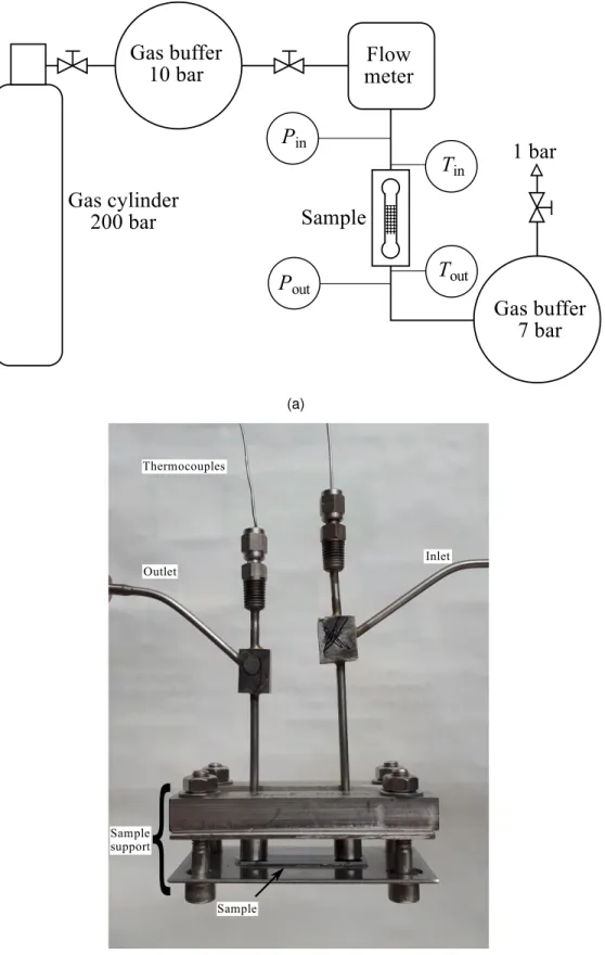
Experiments were performed with helium gas as the working fluid. Fig. 5a shows a diagram of the experimental set-up. Helium gas is supplied by a high pressure gas bottle (200 bar). In order to protect the rest of the experimental assembly, the gas is expanded in a first buffer before passing through the sample. The gas flow and the second buffer pressure are manually controlled by three precision needle valves. The gas flow rate and the inlet-outlet pressures are recorded by a thermal mass flow meter (BrooksDelta, 0.55 N L{min) and two pressure transducers (Keller PR33X, 0 to 20 bar). Two k-type thermocouples are also installed inside the capillaries located upstream and downstream the channel, to record the inlet and outlet temperatures. By using the ideal gas law to estimate the density (ρ“ P M {RT ) and by considering the mass flow conserva-tion along the exchanger (ρU S “ const), it is easy to demonstrate that the ratio between outlet and inlet velocities is simply Uout{Uin9pPin{PoutqpTout{Tinq. In present experiments, temperature
measurements show that the ratio Tout{Tinremains close to unity (0.99ď Tout{Tin ď 1.11 ). Thus,
ex-changer in our installation the ratio of inlet and outlet pressure has been kept as close as possible to unity. To do that the outlet pressure in the second buffer tank was kept at around 8-10 bar for a pressure drop globally lower than 2 bar (one experiment at 3 bar of maximum). As a result, the velocity of the flow in the exchanger can be calculated directly from the measured mass flow rate at the inlet as follow U “ Qm{pρStotaleεq. The averaged gas density ρ and also average viscosity
µare calculated from the average inlet/outlet temperature Tm and pressure Pmusing respectively
the ideal gas law ρ “ PmM{RTm and the correlation proposed by Petersen [36] (Eq. 6.1 in the
paper).
As shown in Fig. 5b, the assembly has been designed to facilitate the replacement of samples. The metal structure holds the fluidic connections on the inlet and outlet ports. In the experiments presented here with gaseous helium as the working fluid, it was verified that the Knudsen number remains small enough (K « 0.015) to avoid slip-like condition at the wall, so the fluid is considered as a continuum [37]. It can also be noted that the regular pressure drop induced in the empty parts of the channel (« 12 mm) has been subtracted from the measured pressure drop [38]. The relative part of this regular pressure drop corresponds to less than 2% of the total measured pressure drop so that the total measured pressure drop is mainly generated by the cylinders.
Preliminary validation
In order to check the validity of measurements, some empty channels (without porous region) were micro-machined using KOH wet anisotropic etching. This method enables to produce chan-nels with a perfectly well defined trapezoidal shape cross section.
Channels were etched with a small depth to obtain a sufficiently high pressure drop together with a gas flow (10 ď H ď 30µm, W “ 2 mm width ). With such a low channel aspect ratio (H{W ă 2%), the flow inside these calibration channels is similar to the one between two parallel plates. The results presented in Fig. 6, show clearly a good agreement with the theoretical friction factor expected for such a reference flow (f “ 96{Re). At small Reynolds numbers large error bars are associated to the friction factor. This is due to the larger uncertainty in the measurement of the flow rate at low Reynolds numbers, typically for Reă 10. For Re ą 10, the relative uncertainty on the measurement of the Reynolds number for experiments with empty channels or channels with
cylinders is lower than 10%.
Experimental results
Experimental friction factor
Experimental measurements of the friction factor were performed for 11 samples on a Reynolds number range of 1 ă Re ă 30. The channels were tested under the same outlet pressure condi-tions (« 6.7bar) and under the same average gas temperature (« 20˝C). The flow rate range is
0.02ď Qv ď 0.54 N L{min while the measured pressure drop range is 0.070 ď ∆P ď 3.0 bar. An
example of friction factors obtained for samples with the same e« 20 µm and different porosities, is reported in Fig. 7 as a function of the Reynolds number. As expected, it is first observed that at low Reynolds number the friction factor evolves as f “ P o{Re. Each sample with a given porosity can thus be characterized by one Poiseuille number. As previously for friction factor measure-ments inside empty channels, a high inaccuracy of measurement is obtained for Reynolds number below 10. That is why the Poiseuille number of each sample has been estimated only for data with Reą 10 insuring an uncertainty on its measurement lower than 20%.
Secondly, it is found that globally the friction factor tends to increase with the porosity ε for a fixed value of the apex angle (here α « 33˝). In the literature, the dependency of the friction
factor on the porosity for a porous medium in regenerator applications was first mentionned by Gedeon & Wood [39] but not proved experimentally (Eq. 2.3 in the report of the reference). Even if this behaviour was not clearly noticed by the authors, the increase of the friction factor with ε was also present in numerical results presented by Costa et al. [40] (Fig. 17 in the paper). In that reference, the authors proposed a single global correlation for four different porosities (ε “ 0.52, 0.60, 0.64, 0.72). Nevertheless, it is important to mention that the increase of ’f’ with ε does not mean that increasing the porosity generates higher pressure drop since many parameters can be affected by ε.
The experimental Poiseuille numbers are plotted versus the porosity in Fig. 8 (* symbols) and are reported in the last column of Tab. 1. These experimental data are compared to the results of numerical simulations presented below. For an apex angle α« 33˝, both numerical and experimental results display a slight increase of the friction factor when increasing the porosity.
The small discrepancies between the experimental measurements and the numerical results can be induced by sample border effects (walls) so that the flow is not completly 2D. In all the cases, the Poiseuille number is always higher or equal to the limit given for a flow between two parallel plates (P o “ 96). This behaviour will be understood in section ”Parallel-plates flow analogy” by considering the flow at the scale of the channel formed between cylinders.
Our results are in agreement with the main observation made by Sparrow & Grannis on the fact that at low apex angle, the Poiseuille number remains nearly constant for εď 0.60 (Fig. 11 & 12 in [22]). However, a direct comparison with this previous work is made difficult, because the authors do not use exactly the same velocity scale as ours for the calculation of the Reynolds numbers and the friction factors. Nevertheless, the present work displayed the same order of magnitude of Poiseuille numbers than what has been presented by this team (P o « 100 for α “ 45˝ and
εď 0.70).
Moreover, one of the most important result of this work is that the diamond-shaped array geometry is found to generate experimentally lower Poiseuille numbers than conventional solutions used to design regenerators. As reported in Fig. 8, measured Poiseuille numbers are found to be smaller that stacked woven wire matrices (P o“ 123, Costa et al. [41] for 1 ď Re ď 400) or stacked sphere matrices randomly arranged (P o “ 133, Ergun [42] for moderate Reynolds number, see [43] appendix B) for εď 60´70%. This result confirms that well controlled geometries can improve regenerators pressure losses and more globally heat exchanger performance.
Lastly, another important new result emerging from Fig. 8 is that contrary to the experimental results presented by Vanapalli et al. [20] for sinus (P o « 29.65) or ellipse-shaped (P o « 26.98) cylinders, our experimental results do not display Poiseuille numbers below the parallel-plates limit (P o ď 96 in our case). There is no reason that the Poiseuille number should be lower than the squared cross section channel limit (P o “ 56.9). The result of Vanapalli et al. maybe a consequence of the singular pressure corrections applied to the porous media extremities, or of an inaccurate hydraulic diameter used that does not take into account the additional friction on the bottom and top walls (A1cont).
of exchangers with low pressure drop, and complementary studies on heat transfer efficiency with such a geometry will have to be performed. The dimensional analysis presented now will help to understand that the Poiseuille number depends on porosity before being confirmed by the numerical simulations.
Dimensional analysis
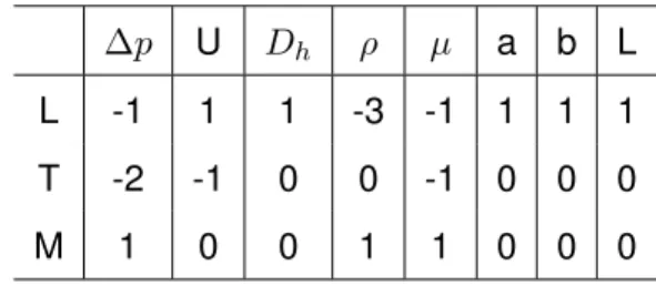
To confirm experimental observations and before developping numerical simulation, a dimen-sional analysis was applied in order to identify the main dimensionless numbers that influence the friction factor in the studied geometries. In our configuration the pressure drop ∆P through the sample can be influenced by the seven following parameters: U , ρ, µ, a, b, Dh and L (the porous
area length). The dimensions of those parameters are recalled in Tab. 2. Note that the porosity εor the interchannel width e are not included since they are both linked to parameters a, b, Dh.
In addition, the channel height H is not taken into account since we consider here a 2D case with a{H ăă 1 and b{H ăă 1. As shown in Tab 2, there is n “ 8 parameters and m “ 3 fundamental dimensions (L, T, M). As a result, applying the Vaschy-Buckingham theorem [44, 45], our system is controlled by n´ m “ 5 dimensionless numbers that can first be expressed as
Π1 “ ∆P U´2ρ´1D 0 h“ ∆P ρU2 (8) Π2 “ µU´1ρ´1Dh´1“ µ U ρDh (9) Π3 “ aU 0 ρ0Dh´1“ a Dh (10) Π4 “ bU 0 ρ0D´1h “ b Dh (11) Π5 “ LU 0 ρ0D´1h “ L Dh (12)
Among those numbers, it is important to note that in our case, the condition Π5 “ L{Dh Ñ 8
is always verified. Our system can thus be reduced to 4 dimensionless numbers that can be rearranged as
Π1 Π5 “ ∆P Dh ρU2L “ f (13) Π´12 “ U ρDh µ “ Re (14) Π3 “ a Dh “ p1 ´ εq{rcospα{2qε{s (15) Π3{Π4 “ a b “ tanpα{2q (16)
Consequently, the dimensional analysis confirms that the friction factor depends on the Reynolds number Re, on the apex angle α (or tanpα{2q) and on the porosity. For a fixed value of the apex angle, the dimensional analysis confirms that the friction factor is influenced not only by the exchanger Reynolds number but also by the porosity value. One can note that this param-eter can be also interpreted as the effect of the variation of the cylinder Reynolds number since Π3{Π2“ U ρa{µ “ ReD. It is important to notice that in the literature, it is known that the pressure
drop in staggered arrangements depends on the center-to-center longitudinal and transversal dis-tances LLand LT{2 (see for example [31]). Since in our geometry the constraint ∆y “ e makes
a direct link between longitudinal and transversal distances, the porosity quantifies here the dis-tances between column center.
Our experimental measurements show that the Poiseuille number increases with the porosity. To go further in the possible use of diamond-shaped arrays for micro regenerators geometry, it is now important to confirm and understand this behaviour and to investigate the effect of varying the apex angle. This is the objective of the next part of the article where those open questions are addressed using numerical simulations.
NUMERICAL SIMULATIONS
In this section, the numerical procedure, the validation of the procedure and results are pre-sented for a 2D flow through a diamond-shaped cylinders array.
Governing equations
One considers the numerical simulation of a flow through a cylinder matrix with a volume averaged mean velocity ’U “ p1{V qş ş ş uxdv’ along the main flow axis. The cylinders aspect ratio
is considered to be small enough so that the flow is in 2 dimensions (i.e. a{H ăă 1). Due to the Reynolds number range, the flow regime is laminar. The local velocity ’u’ and pressure fields
’p’ are given by solving numerically the Navier-Stokes equations for an incompressible Newtonian fluid
∇¨ u “ 0 (17)
ρu¨ ∇u “ ´∇p ` ∇ ¨ τ ` S0 (18)
where τ “ µ`∇u ` ∇Tu˘ is the viscous contribution of the stress tensor, ρ and µ are
respec-tively the fluid density and the dynamic viscosity. The flow is generated by imposing a source term S0 “ Bp{Bx as a negative pressure variation along the x-axis matrix and using periodic boundary
conditions for both velocity and pressure as detailed in the next section.
Numerical procedure
The conservation equations are solved with the finite volume method in 2D with OpenFoam using a double-precision writing format [46]. For solving the Navier-Stokes equations, an upwind second order scheme and a centered second order scheme are used for the spatial discretization of respectively the advective and the diffusive fluxes. The pressure and velocity fields are linked by the SIMPLE algorithm. The convergence of the flow calculation is achieved when the drag coefficient is stable and when the residuals are lower than 10´7.
The calculation domain is presented in Fig. 9a. It corresponds to a periodic pattern with periodic boundary conditions at the inlet and at the outlet for the velocity and the pressure (i.e.
upx “ 0, yq “ upx “ LL, yq and ppx “ 0, yq “ ppx “ LL, yq). An adherence condition is imposed at
Some preliminary simulation tests on a domain corresponding to a concatenation of five periodic patterns have shown that the periodic boundary conditions on velocity and on residual pressure are reached as soon as the second periodic box is passed for present Reynolds range.
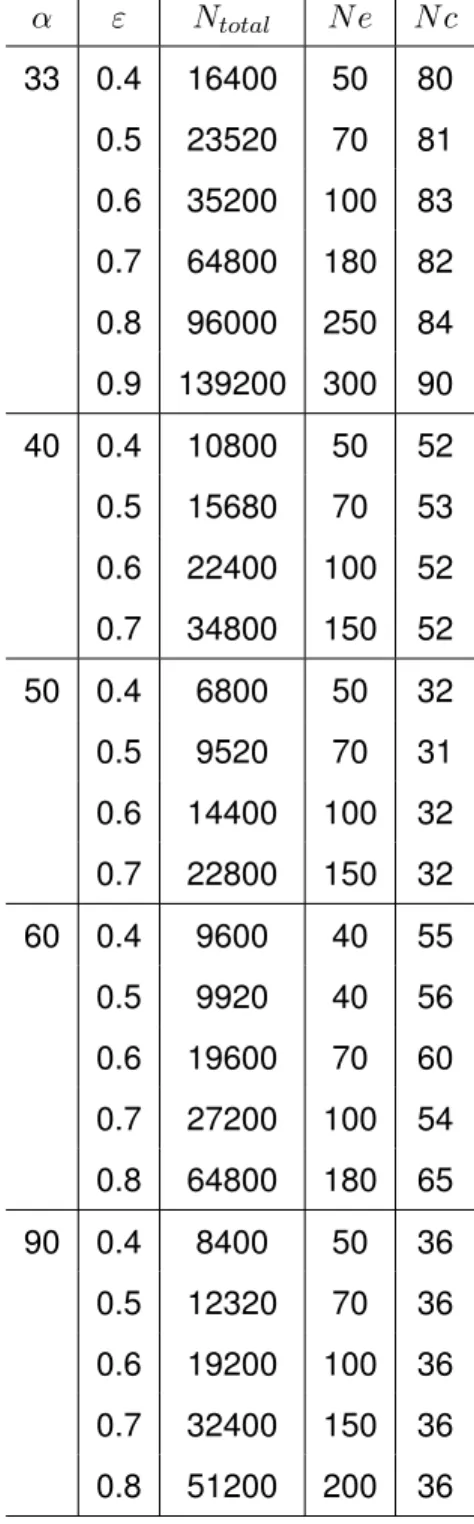
An example of the grid refinement strategy is shown in Fig 9b for a coarse grid. Around the cylinder a refined body fitted rectangular mesh is used. The grid-independence of results has been checked for each case. The size of the grids used in this work is detailed in Tab. 3. Globally, the number of cells between columns faces varies as 50 ă N e ă 300 (N e “ N ∆y). The number of cells along the cylinder surface (2c) is in the range 62ă 2 N c ă 180. And the number of cells between two consecutive apex angles is fixed to be 2 N ∆x “ 10. The number of cells indicated here are linked to segments presented in Fig. 2 (c, e, ∆x, ∆y). In the present simulations, since the Reynolds number remains low the boundary layer are thick. Thus the smallest size of the cell at the cylinder surface is not fixed from a boundary layer constraint but by respecting a cell aspect ratio between 2 and 4 and checking the result independence to the grid refinement.
Numerical results and discussion
The preliminary validation of the numerical procedure was carried out using two test cases. The first test case is the flow between two parallel plates considering a periodic slice. Numerical results show a perfect agreement with the theory with P o “ 96 for 1 ď Re ď 100. The second validation test case is a flow through a staggered arrangement diamond-shaped cylinders matrix with a porosity of ε“ 65% and an apex angle of α “ 45˝ as studied experimentally by Sparrow &
Grannis [16]. A correct agreement is globally found with respectively a difference of 3.8%. 4.5% and 15% for the three measurments presented by the authors (see Fig. 3.5, Tab. 3.2 and Fig. 3.4b in [43]).
In this section, the pressure drop is presented for a flow through diamond-shaped cylinders matrix, with variable apex angles (33ď α ď 90˝), porosity (40 ď ε ď 90%) and Reynolds number
range (1 ď Re ď 30) matching the experimental study. Then, to understand Poiseuille variations, our results are also analysed at the scale of a channel flanked by neighbouring cylinders and at the scale of one cylinder in the matrix.
Pressure drop at the exchanger scale
Some examples of velocity fields obtained by the simulations for Re“ 1 ´ 30, α “ 33 ´ 60 ´ 90˝ are presented in figures 10 and 11 for ε“ 40% and ε “ 80% respectively. In Fig. 10 for ε “ 40%, at Re “ 1 (LHS) it can be observed that whatever the apex angle is, the flow displays a velocity profile very close to the parabolic velocity profile that is usually found for a parallel-plates flow. As shown in the same figure, at Re“ 30 (RHS), the velocity profiles became a bit asymmetric when increasing the apex angle. A velocity deficit is observed just after the top and bottom equator angles but no recirculation is formed at the rear of the cylinder. Present velocity fields are in agreement with previous observations of [22] or [26, 27] (α“ 43 ´ 60˝and ε“ 40 ´ 60 ´ 80%). In Fig. 11 for ε “ 80%, at Re “ 30 (RHS) it is found that the increase of the apex angle generates stronger flow asymmetry compared to ε “ 40%. As a conclusion, the analysis of velocity fields demonstrates that at low Reynolds number, a low porosity and a low apex angle support the establishment of a velocity profile close to the parabolic one expected for creeping flow between two parallel plates.
The corresponding evolutions of friction factor as a function of the Reynolds number for α“ 33 and 90˝are shown in Fig. 12. In agreement with the experiments, it is verified that the calculated friction factor increases with the porosity ε and remains always higher than the one expected for the flow through a flat rectangular channel (f ě 96{Re or P o ě 96). In addition, numerical simulations indicate also that the friction factor can increase substantially with the apex angle. This may be explained by the flow deviation induced by an α enlargement. An increase of the pressure drop due to flow deviation has been also reported experimentally by [47] for the case of a flow following a sinusoidal trajectory. However, the dependency of the friction factor on the porosity is for the moment not clearly explained.
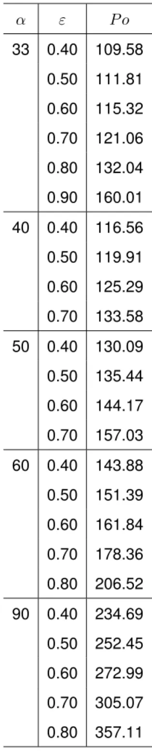
Globally at low Reynolds number the Stokes flow is clearly verified (f91{Re) so that a Poi-seille number P o“ f Re can be affected to each geometrie. Poiseille numbers obtained from the numerical simulations are reported in Table 4 and plotted in Fig. 8. Considering the experimental errorbars with an uncertainty around 20% on the experimental Poiseuille number, a good agree-ment is found between the numerical results and the experiagree-mental measureagree-ments for α“ 33˝. To
justify and to better understand the effect of the porosity and apex angle on the Poiseuille number, we propose now to analyse the flow at different scales.
Parallel-plates flow analogy
It is a common practice, for porous media, to make the analogy with channelling flows to try to understand the effect of the different parameters [42, 48]. This approach is particularly justified in our geometry considering previous observation on the velocity field. The channel formed between cylinders, corresponding to the area limited by red dashed lines in Fig. 2, is now considered for applying the parallel-plates flow analogy. Thus, in order to make possible the analysis at the scale of the channel formed between cylinders, the length L1L, which corresponds to the averaged flow path length, is now introduced (see Fig. 2).
By considering the mid distance between the top and bottom walls, an estimation of the flow path length can be given as following (for more details see [43])
L1L“ 4∆xa1 ` pa{p2bqq2` 2pb{2 ´ ∆xqa1 ` pa{bq2
(19)
As for the whole exchanger, the hydraulic diameter, the Reynolds number and the friction factor corresponding to this channel can be defined as
Dh1 “ 4eH{p2pe ` Hqq “ 4e{p2pe{H ` 1qq « 2e (20)
f1 “ D 1 h L1L ∆P 1{2ρU2 “ D1h L1L LL Dh f “ D 1 h Dh LL L1Lf (22)
The channel friction factor (f’) can thus be calculated directly from previously defined friction factor for the whole exchanger (f) and from the length ratios L1L{LLand D1h{Dh. Those two length
ratios are plotted in Fig. 13 as a function of the porosity for different apex angles.
A first attempt to apply the ’channel’ flow analogy for diamond-shaped cylinders array was proposed by Grannis & Sparrow [22]. They did not take into account real flow path (L1L) and only use the porous media hydraulic definitions. In porous media the length ratio L1L{LL corresponds
to the so-called tortuosity that compares the mean real path length of the flow through the pores network to the length of the porous matrix. By definition this ratio is larger or equal to unity. In Fig. 13a, one can show that for present geometry even if the range of apex angle is large (33ď α ď 90˝) the tortuosity remains lower than 1.4. Moreover the tortuosity seems to be significantly affected by the porosity only for αą 50˝. In addition, decreasing the apex angle makes this ratio very close
to unity. As a result one particularity of the diamond-shaped cylinder matrix regenerators is to be characterized by a low tortuosity. In the same time, as depicted in Fig. 13b, the hydraulic diameter ratio Dh1{Dh is found to decrease when the porosity increases, and to be lower than unity. For
a given porosity and total volume, this ratio is proportional to the corresponding wetted surfaces ratio so that Dh1{Dh9Acont{A1cont. Since in our geometry, the fluid is not wetting all the border of
the channel formed between cylinders (area delimited by a red dashes line in Fig. 2) the wetted surface Acont is smaller than the one expected in a straight channel having the same length L1L
so that Acont ă A1cont and D1h{Dh ă 1. The observation that in both numerical and experimental
approaches the Poiseuille number tends to the parallel-plates flow limit P o“ 96 when decreasing the porosity and apex angle, is therefore explained by the behaviour D1
h{Dhpα Ñ 0, ε Ñ 0q Ñ 1
and L1L{LLpα Ñ 0, ε Ñ 0q Ñ 1. In those conditions the flow is similar to the one in an assembly of
parallel flat channels with length LL“ L1Land hydraulic diameter Dh“ D1h “ 2e. In addition, when
contact with the top an bottom channel walls AWcontis predominant compared to the wetted surface
in contact with the column Acontand the hydraulic diameter tends to Dh“ 2H. If the aspect ratio is
low H{W ăă 1, the Poiseuille number when ε Ñ 1 should also be P o “ 96 and the main channel flow become similar to the parallel-plates flow.
It is now possible to estimate the Poiseuille number P o1 corresponding to the pressure loss at the scale of the channel formed between cylinders as follow
P o1 “ Re1f1 “ˆ D 1 h Dh ˙2 LL L1Lf Re“ ˆ Dh1 Dh ˙2 LL L1LP o (23)
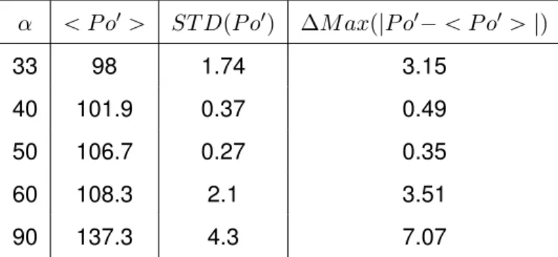
The evolution of P o1 as a function of the porosity is presented in Fig. 14a. It is first observed
that the Poiseuille variation is much lower than previously in Fig. 8 (95 ă P o1 ă 140 whereas 107 ă P o ă 357) and that for a given apex angle α the value of P o1 is weakly affected by the variation of the porosity. To verify this assertion, the average value of P o1 for a given angle α (ă P o1 ą), the standard deviation compared to this value (ST DpP o1q) and the maximal absolute difference with this average value (∆M axp|P o1´ ă P o1 ą |q) have been reported in Tab 5. For the simulations presented here, the standard deviation and the maximal difference are both lower than 6%. As a consequence, the quasi stagnation of the Poiseuille number of the channel P o1 versus εshow us that the dependence of the Poiseuille number P o on the porosity of the exchanger is mainly explained by the change of the scale considered to analyse the results (exchanger scale / channel scale).
In addition, as shown in Fig. 14b, it is therefore possible to plot the evolution of the average Poiseuille number ă P o1 ą as a function of the apex angle α. The evolution of ă P o1 ą can be fitted by
with α in radian. This relation was constructed considering that, as mention previously, ă P o1 ą pα Ñ 0q “ 96 and using the aspect ratio tanpα{2q “ a{b that reflects the velocity field deviation intensity induced by the apex angle value. The increase ofă P o1 ą with the apex angle
can be explained by the fact that the highest the apex angle is, the strongest the flow deviation and associated pressure loss are. In Fig. 14b, it can be noticed that the fact of not having data for εlarger than 70% for α“ 40˝ and 50˝ may explained that corresponding values foră P o ą are a bit higher than the curve given by Eq. 24.
This data analysis have the advantage to enable the estimation of P opα, εq values from an average value of P o that is only a function of α (Eq. 24). From Eq. 23 and Eq. 24, it becomes now possible to estimate the effect of the apex angle and to use the hydraulic diameter ratio and the tortuosity to estimate the effect of the porosity on the Poiseuille number considered at the scale of the whole exchanger. The results reported in Fig. 8 (dash lines) are found to be in good agreement with the numerical simulations, especially at low apex angle.
Collective effect on drag coefficient
In the literature on collective effect on drag, it is claimed that the variation of the drag exerted on one cylinder in an array can be influenced by two contributions. If two cylinders are aligned in the direction of the flow, the decrease of the distance between them tends to reduce the drag : this is the longitudinal contribution (see for example [49] ). If two elements are now aligned perpendicularly to the flow direction, then it is admitted that the drag of both cylinders increases if they get closer because of the fluid blockage and the induced increase of friction: this is the transversal contribution (see for example [50] or [51]). Consequently, the drag exerted on one cylinder results from the interaction of these two contributions.
Some example of the typical evolution of the drag coefficients of a cylinder in the matrix are plotted in Fig. 15 for α “ 33 and 90˝. Globally, for a given angle α, it is observed that the
drag increases systematically when the porosity decreases and the spacing between cylinders is reduced. In addition, the correlation found by Sochinskii et al. [52] for a single diamond-shaped cylinder is also reported in this figure. As for an array of particles [53, 42], it is found that the drag for one cylinder in a matrix is always larger than the one expected for a single cylinder. This
behaviour is also in agreement with the literature on collective effect on drag force for a staggered array of cylinders [2]. We can note that, at low Reynolds numbers, the drag coefficient seems to remains inversely proportional to the cylinder Reynolds number even if the porosity is reduced.
To understand the link between the collective effect on drag and the friction factor correspond-ing to the pressure loss in the cylinder matrix, it is possible to write the momentum global balance for a volume corresponding to the present periodic pattern. The calculation developed in AP-PENDIX A shows that the pressure loss is induced by the force applied on the cylinders so that the drag and friction coefficients are linked by the relation
CD « f LLLT Dh2a “ ˆ P o LLLT 2 D2 h ˙ 1 ReD “ ˜ ă P o1 ą L1 LLT 2 D1 h 2 ¸ 1 ReD (25)
This result, usually presented as Eq. 30, is also found by Larson & Higdon [54] or Van der Hoef et al. [55] and has been verified in our simulations with a maximum difference of 3%.
From the begining of Eq. 25, it can be shown that the concomitant increase of f and decrease of CDwith the porosity can be explained by the strong reduction of the ratiopLLLTq{pDh2aq 9 ε´1
that is inversely portional to the porosity. Indeed, by considering Eq. 3, ab{pLLLTq “ 1 ´ ε and
tanpα{2q “ a{b, this ratio can be simply expressed as
LLLT
Dh2a
“ r2sinpα{2qεs´1 (26)
From Eq. 25 and 24, it becomes now possible to estimate the drag coefficient at low Reynolds numbers. The result is reported as dotted lines in Fig. 15 and is in a very good agreement with our simulation results. Consequently, the analysis of the flow at the scale of the channel formed between cylinders has allowed us to develop a description of an average Poiseuille number, that can be used for the prediction of pressure losses at the scale of the heat exchanger but also for
the estimation of collective effects on the drag coefficient at the scale of one cylinder.
Comparison to circular cylinders and spherical particles arrays
This section compares our method and results on Poiseuille numbers with those expected for a square and staggered arrangement of circular cylinders matrix and for conventional spherical particles arrays.
The collective effect on drag for circular cylinders arrays is well documented, and the Poiseuille number of such an arrangement can be calculated directly from the drag force. The detail of the calculations that make the link between the Poiseuille numbers and the drag for a circular cylinders array is presented in the first part of APPENDIX B. The numerical results of Sangani & Acrivos [2] and the hybrid model of Yeom et al. [6] constructed from experimental measurements are reported in Fig. 16. Our first observation is that the Poiseuille number obtained using a circular cylinders array is always higher than the one using a diamond-shaped cylinders array, except for α “ 90˝. This result allows to appreciate the potential of using a diamond-shaped cylinder geometry for a low pressure loss design for heat exchangers operated at low and moderate Reynolds numbers. In contrast with our results, the obtained Poiseuille variation with the porosity for circular cylinders exhibits a ’U’ shape reaching a minimum value around ε“ 0.70´75. The increase of the Poiseuille number when decreasing the porosity is thought to be the consequence of the strong variations of the cross section of the flow along its path, generating acceleration/deceleration when decreasing the porosity. Furthermore the increase of the Poiseuille number when increasing the porosity is found to be in agreement with our results for α “ 90˝ and typically for ε ą 0.8. This behaviour is first explained by the fact that when the porosity gets close to unity the flow around the cylinders gets close to the flow around a single cylinder whatever the arrangement is. Secondly, as reported recently by Sochinskii et al. [52] the drag for a circular cylinder is very close to the one obtained from a diamond-shaped cylinder with an apex angle of α “ 90˝. As a result, the arrangement of
circular or 90˝ diamond-shaped cylinders gives similar drag law and Poiseuille number when the
porosity tends to unity. This is confirmed by the fact that the dimensionless drag force predicted by the relation proposed by Yeom et al. [6] for ǫ“ 0.99 with a square array of circular cylinders ( F{µU “ 3.16) is close to the dimensionless drag force experienced by a single diamond-shaped
cylinder with α“ 90˝at low Reynolds number (F{µU “ rpCD{2qpDhqρU2s{pµU Hq “ 6.98{2 “ 3.49,
[52]).
In addition, as mentioned previously, the Ergun correlation is dedicated to randomly arranged spherical particles arrays at moderate Reynolds numbers. In the literature, the drag force on well controlled arrangements of spherical particles is also well documented. The details of the calculations that make the link between the Poiseuille numbers and the drag for spherical particles arrays are presented in the second part of APPENDIX B. The numerical results of Sangani & Acrivos [56], valid for low Reynolds number, are now reported in Fig. 16 for simple, body centred and face centred cubic arrays of spherical particles. It is found again that, typically for ε ď 70%, those specific sphere networks tend to generate higher P o than diamond-shaped cylinders arrays but lower P o than circular cylinders arrays. The Poiseuille number curves for body and face centred cubic arrays still exhibit a ’U’ shape. Meanwhile for the simple cubic array, P o shows a monotonous increase with the porosity. As for the circular cylinders arrays, at high porosity (εą 80%) the type of arrangements do not influence the Poiseuille number that increases strongly with the porosity. In fact, for a very dilute particle flow at low Reynolds numbers, the drag coefficient of the particles is close to the one of a single particle (CD “ 24{ReD, F “ 3πU µD [57]). Rearranging equations
from APPENDIX B, with such a drag law, one finds easily that at high porosity Poiseuille numbers follow
P opǫ Ñ 1q “ Kε
2
1´ ε (27)
with K “ 16 for spherical particles arrays. As reported in Fig. 16, this asymptotic behaviour is in agreement with the results of Sangani & Acrivos [56]. The identification of the behaviour of P o for a dilute flow with the circular cylinders arrays is made difficult because of the com-plexity of available drag laws at low Reynolds numbers. Similarly, for the present geometry with diamond-shaped cylinders arrays, under very dilute conditions the drag experienced by cylinders remains close to the one on a single cylinder whatever the arrangement is (CD « 7{ReD for
ReD ď 10 [52]). The rearrangement of the equations show that the asymptotic behaviour of
very dilute diamond-shaped cylinders arrays follows the same previous equation (Eq. 27) with K “ 14 tanpα{2q{prtanpα{2qs2
` 1q. As shown in Fig. 16, it is difficult with our results (where the maximum porosity is 90%) to verify this limit. Nevertheless, the fact that the K factor increases with the apex angle support the idea that, as observed previously in Fig. 8, P o is less influenced by the porosity when decreasing the apex angle. It is important to note that such a divergence of the Poiseuille number when ǫ Ñ 1 could be only observed experimentally for condition close to
a unbounded 2D flow (a{H ăă 1, a{W ăă 1 and AW
cont ăă Acont). As explained previously, by
increasing the porosity if AW
cont ąą Acont the pressure drop will be controled by the main channel
SUMMARY AND CONCLUSIONS
In this work, three complementary approaches(experiments, dimensional analysis and numer-ical simulations) were developped to investigate pressure losses in diamond-shaped cylinders arrays at moderate Reynolds numbers. Experiments have been performed to study the influence of the porosity on the friction factor on a micro-fabricated diamond-shaped cylinders array with an apex angle of α“ 33˝.
‚ The measurements exhibited a weak increase of the Poiseuille number with the porosity, con-firming a trend that can be found in recent numerical studies of Costa et al. [40].
‚ The fact that the Poiseuille number depends on the porosity is confirmed by a dimensional analysis.
‚ Experimental Poiseuille numbers are higher than the value expected from a two parallel plates geometry (P o ě 96). But they remains lower than those reached by conventional solutions used up to now to design regenerators (spheres and wires stacking arrays or even circular cylinders arrays). That result enhances all the capability of the diamond-shaped geometry for the design of heat exchangers with low pressure drop, enabling the reduction of exchangers hydraulic power.
The flow in diamond-shaped cylinders arrays has been investigated using numerical simula-tions for a large range of apex angles 33˝ ď α ď 90˝.
‚ The numerical results confirm the increase of the Poiseuille number with the porosity, but also with the apex angle.
‚ The analysis of the results at the scale of a channel located between two adjacent cylinders, shows that the role of the porosity is mainly explained by the variation of the real flow path length. The contribution of the apex angle variation is the consequence of the pressure drop induced by the flow deviation.
‚ The analysis of the collective effect on drag is found to be in agreement with the literature and shows an increase of the drag when the distance between cylinder is reduced.
‚ From a multi-scale analysis, a simple correlation has been identified that enables the descrip-tion of both the Poiseuille number and the drag coefficient variadescrip-tion for a large range of apex
angles 33˝ ď α ď 90˝and porosities 40ď ε ď 90% at moderate Reynolds number.
Forthcoming works will be devoted to experimentally characterize the role of the apex angle of the diamond-shaped cylinders on the Poiseuille number for low Reynolds numbers, and to verify that the results match those obtained numerically for αą 33˝. The main challenge will be then to
investigate numerically and experimentally the heat exchange efficiency for such a geometry.
ACKNOWLEDGMENTS
The authors would like to thank LANEF laboratory of excellence as well as SBT/CEA and LEGI for supporting this work. We gratefully acknowledge the assistance of Cyrille Bonamy from LEGI for his help in numerical simulations with OpenFoam, of David Garcia and of Julien Inigo from SBT for assembling the experimental installation. We also thank Kabir Bashir Shariff for his helpful involvement during his master internship. Authors would like to also acknowledge the technical staffs of PTA (CEA) and Nanofab (N ´eel Institute) micro/nanofabrication platforms for the assistance in micro-fabrication of samples.
NOMENCLATURE
Roman symbols
a diamond-shaped cylinder width, m
Acont cylinder wetted surface in contact with the fluid, m2
AWcont channel caps wetted surface in contact with the fluid, m2
A1cont wetted surface for the channel considered between cylinders, m2
b diamond-shaped cylinder length, m
c diamond-shaped cylinder half side length, m
CD drag coefficient
D circular cylinder or spherical particle diameter, m Dh hydraulic diameter of the exchanger, m
D1h hydraulic diameter of the channel formed by cylinders, m
e distance between cylinders walls and width of channel formed by cylinders, m f friction factor at the exchanger scale
f1 friction factor considering the channel formed by cylinders
Fd drag force vector for one cylinder, N
F drag force magnitude per cylinder length (F “ ||Fd||{H), N {m
H cylinder height (or etching height), m LT width of the periodic domain, m
LL width of the periodic domain, m
L1L estimation of the real flow path length along the channel in the periodic domain, m L experimental exchanger length section with the diamond-shaped cylinders array, m
p local pressure, P a
P o Poiseuille number at the scale of the exchanger (P o“ f Req P o1 Poiseuille number at the channel (P o1 “ f1Re1q
Qm mass flow rate, kg s´1
R Ideal gas constant (R“ 8.314 J mol´1K´1q
Re1 Reynolds number based on the channel hydraulic diameter and mean flow velocity (Re1 “ U D1h{ν)
ReD cylinder Reynolds number based on the cylinder width and mean flow velocity (ReD “ U a{ν)
S cross section area, m2
Tm average inlet/outlet temperature, K
u local velocity vector, m s´1
U mean flow velocity, m s´1
Greek symbols α apex angle,˝ ε exchanger porosity µ dynamic viscosity, P a s ν kinematic viscosity (ν“ µ{ρ), m2 s´1 ρ density, kg m´3 Mathematical symbol || ´ || vector magnitude REFERENCES
[1] Zukauskas, A., 1972. “Heat transfer from tubes in cross flow”. Adv. Heat Transfer,8, pp. 93–
160.
[2] Sangani, A., and Acrivos, A., 1982. “Slow flow past periodic arrays of cylinders with applica-tion to heat transfer”. Int. J. Multiph. Flow,8, pp. 193–206.
[3] Metzger, D., Berry, R., and Bronson, J., 1982. “Developing heat transfer in rectangular ducts with staggered arrays of short pin fins”. J. Heat Transfer,104, pp. 700–706.
[4] Stanescu, G., Fowler, A., and Bejan, A., 1996. “The optimal spacing of cylinders in free-stream cross-flow forced convection”. Int. J. Heat Mass Transf.,39, pp. 311–317.
transfer across a pin fin micro heat sink”. Int. J. Heat Mass Transf.,48, pp. 3615–3627.
[6] Yeom, J., Agonafer, D., Han, J., and Shannon, M., 2009. “Low reynolds number flow across an array of cylindrical microposts in a microchannel and figure-of-merit analysis of micropost-filled microreactors”. J. Micromech. Microeng.,19, p. 065025.
[7] Li, Q., Chen, Z., Flechtner, U., and Warnecke, H., 1998. “Heat transfer and pressure drop characteristics in rectangular channels with elliptic pin fins”. Int. J. Heat Fluid Flow, 19,
pp. 245–250.
[8] Uzol, O., and C, C., 2005. “Heat transfer, pressure loss and flow field measurements down-stream of staggered two-row circular and elliptical pin fin arrays”. J. Heat Transfer, 127,
pp. 458–471.
[9] Bahaidarah, H., Anand, N., and Chen, H., 2005. “A numerical study of fluid flow and heat transfer over a bank of flat tubes”. Numer. Heat Tr. A-Appl.,48(4), pp. 359–385.
[10] Molki, M., Faghri, M., and Ozbay, O., 1994. “A new correlation for pressure drop in arrays of rectangular blocks in air-cooled electronic units”. J. Fluids Eng.,116(4), pp. 856–861.
[11] Chen, S., and Jendrzejczyk, J., 1987. “Fluid excitation forces acting on a square tube array”. J. Fluids Eng.,109(4), p. 415423.
[12] Bejan, A., and Morega, A., 1993. “Optimal arrays of pin fins and plate fins in laminar forced convection”. J. Heat Transfer,115, pp. 75–81.
[13] Sara, O., 2003. “Performance analysis of rectangular ducts with staggered square pin fins”. Energy Convers. Manage.,44, pp. 1787–1803.
[14] Jeng, T., and Tzeng, S., 2007. “Pressure drop and heat transfer of square pin-fin arrays in in-line and staggered arrangements”. Int. J. Heat Mass Transf.,50, pp. 2364–2375.
[15] Ruhlich, I., and Quack, H., 1999. “Investigations on regenerative heat exchangers”. Cryocoolers 10, edited by RG Ross Jr., pp. 265–274.
[16] Sparrow, E., and Grannis, V., 1991. “Pressure drop characteristics of heat exchangers con-sisting of arrays of diamond-shaped pin fins”. Int. J. Heat Mass Transfer,34, pp. 589–600.
[17] Chyu, M., Hsing, Y., and Natarajan, V., 1998. “Convective heat transfer of cubic fin arrays in a narrow channel”. J. Trubomach.,120, pp. 362–367.
[18] Tanda, G., 2001. “Heat transfer and pressure drop in a rectangular channel with diamond-shaped elements”. Int. J. Heat Mass Transf.,44, pp. 3529–3541.
[19] Jeng, T., 2006. “Thermal performance of in-line diamond-shaped pin fins in a rectangular duct”. Int. Commun. Heat Mass Transf.,33, pp. 1139–1146.
[20] Vanapalli, S., Ter Brake, H., Jansen, H., Burger, J., Holland, H., Veenstra, T., and Elwenspoek, M., 2007. “Pressure drop of laminar gas flows in a microchannel containing various pillar matrices”. J. Micromech. Microeng.,17, pp. 1381–1386.
[21] Rasouli, E., and Narayanan, V., 2016. “Single-phase cryogenic flow and heat transfer through microscale pin fin heat sinks”. Heat Transf. Eng.,37(11), pp. 994–1011.
[22] Grannis, V., and Sparrow, E., 1991. “Numerical simulation of fluid flow through an array of diamond-shaped pin fins”. Numer. Heat Tr. A-Appl.,19(4), pp. 381–403.
[23] Umeda, S., and Torii, S., 2012. “Numerical and experimental study on thermal fuild flow over twin diamond-shaped cylinders in free stream”. 15th International Symposium on Flow Visualization, Minsk, Belarus, June 25-28.
[24] Torii, S., and Umeda, S., 2013. “Flip-flop flow control inside streamwise diverging diamond-shaped cylinder bundles with concavities”. J. Flow Control, Measurement Visualization, 1,
pp. 77–85.
[25] Hirasawa, S., Fujiwara, A., Kawanami, T., and Shirai, K., 2014. “Forced convection heat transfer coefficient and pressure drop of diamond-shaped fin-array”. J. Electronics Cooling Thermal Control,4, pp. 78–85.
[26] De Smet, J., Gzil, P., Vervoort, N., Verelst, H., Baron, G., and Desmet, G., 2004. “Influence of the pillar shape on the band broadening and the separation impedance of perfectly ordered 2-d porous chromatographic media”. Anal. Chem.,76, p. 3716.
[27] De Smet, J., Gzil, P., Vervoort, N., Verelst, H., Baron, G., and Desmet, G., 2005. “On the optimisation of the bed porosity and the particle shape of ordered chromatographic separation media”. J. Chromatogr. A,1073, pp. 43–51.
[28] De Pra, M., De Malsche, W., Desmet, G., Schoenmakers, P., and Kok, W., 2004. “Pillar-structured microchannels for on-chip liquid chromatography: Evaluation of the permeability
and separation performance”. J. Sep. Sci.,30, p. 1453.
[29] Rashidi, S., Bovand, M., Pop, I., and Valipour, M., 2014. “Numerical simulation of forced convective heat transfer past a square diamond-shaped porous cylinder”. Transp. Porous Med.,102, pp. 207–225.
[30] Kays, W., and London, A., 1964. “Compact heat exchangers”. New York: McGraw-Hill, p. chapters 1 and 7.
[31] Gaddis, E., and Gnielski, V., 1985. “Pressure drop in horizontal cross flow across tube bun-dles”. Int. Chem. Eng.,25(1), pp. 1–15.
[32] Kosar, A., Mishra, C., and Peles, Y., 2005. “Laminar flow across a bank of low aspect ratio micro pin fins”. J. Fluids Eng.,19(4), p. 419.
[33] Kosar, A., Schneider, B., and Peles, Y., 2011. “Hydrodynamic characteristics of crossflow over mems-based pillars”. J. Fluids Eng.,133, pp. 081201–1.
[34] Tullius, J., Tullius, T., and Bayazitoglu, Y., 2012. “Optimization of short micro pin fins in minichannels”. Int. J. Heat Mass Transf.,55, pp. 3921–3932.
[35] Rueda Villegas, L., Colombet, D., Guiraud, P., Legendre, D., Cazin, S., and Cockx, A., 2019. “Image processing for the experimental investigation of dense dispersed flows : Application to bubbly flows”. Int. J. Multiph. Flow,11, pp. 16–30.
[36] Petersen, H., 1970. “The properties of helium: Density, specific heats, viscosity, and thermal conductivity at pressures from 1 to 100 bar and from room temperature to about 1800 k”. Roskilde, Denmark: Riso National Laboratory. Denmark. Forskningscenter Risoe. Risoe-R,
224.
[37] Colin, S., 2005. “Rarefaction and compressibility effects on steady or transient gas flows in microchannels”. Microfluid. Nanofluid.,1, pp. 268–279.
[38] Mossaz, S., Colombet, D., Ledoux, G., and Ayela, F., 2015. “Role of the thermal entrance length on the viscous heating in microchannels”. Microfluid. Nanofluid.,19, pp. 1325–1333.
[39] Gedeon, D., and Wood, J., 1996. “Oscillating-flow regenerator test rig: hadware and theory with derived correlations for sreens and felts”. NASA CR-198442.
Prieto, J., 2014. “Experimental and numerical flow investigation of stirling engine regenerator”. Energy,72, pp. 800–812.
[41] Costa, S., Barrutia, H., Esnaola, J., and Tutar, M., 2013. “Numerical study of the pressure drop phenomena in wound woven wire matrix of a stirling regenerator”. Energy Convers. Manag.,67, pp. 57–65.
[42] Ergun, S., 1952. “Fluid flow through packed columns”. Chem. Engr. Prog.,48, pp. 89–94.
[43] Sochinskii, A., 2018. “First step toward the miniaturisation of space cryocoolers”. PhD Thesis, Grenoble Alpes University.
[44] Vaschy, A., 1892. “Sur les lois de similitude en physique”. Annales t ´el ´egraphiques, 19,
pp. 25–28.
[45] Buckingham, E., 1914. “On physically similar systems, illustration of the use of dimensional equations”. Phys. Rev. 4,4, pp. 345–376.
[46] Weller, H., Tabor, G., Jasak, H., and Fureby, C., 1998. “A tensorial approach to computational continuum mechanics using object-oriented techniques”. Comput. phys.,12, p. 620.
[47] Huang, H., Wu, H., and Zhang, C., 2018. “An experimental study on flow friction and heat transfer of water in sinusoidal wavy silicon microchannels”. J. Micromech. Microeng., 28,
p. 055003.
[48] Bird, R., Stewart, W., and Lightfood, E., 2002. “Transport phenomena, 2nd ed.”. John Wiley and sons, inc.
[49] Mulholland, J., Srivastava, R., and Wendt, J., 1988. “Influence of droplet spacing on drag coefficient in nonevaporating, monodisperse streams”. AIAA Journal,26, pp. 1231–1237.
[50] Kim, I., Elghobashi, S., and Sirignano, W., 1993. “Three-dimensional flow over two spheres placed side by side”. J. Fluid. Mech.,246, pp. 465–488.
[51] Thrift, A., Brumbaugh, S., Thole, K., and Kohli, A., 2010. “A methodology to measure aero-dynamic forces on cylinders in channel flow”. J. Fluids Eng.,132(8), p. 08140.
[52] Sochinskii, A., Colombet, D., Medrano Mu ˜noz, M., Ayela, F., and Luchier, N., 2019. “Flow and heat transfer around a diamond-shaped cylinder at moderate reynolds number”. Int. J. Heat Mass Transf.,142, p. 118435.