HAL Id: tel-02493080
https://pastel.archives-ouvertes.fr/tel-02493080
Submitted on 27 Feb 2020
HAL is a multi-disciplinary open access
archive for the deposit and dissemination of
sci-entific research documents, whether they are
pub-lished or not. The documents may come from
teaching and research institutions in France or
abroad, or from public or private research centers.
L’archive ouverte pluridisciplinaire HAL, est
destinée au dépôt et à la diffusion de documents
scientifiques de niveau recherche, publiés ou non,
émanant des établissements d’enseignement et de
recherche français ou étrangers, des laboratoires
publics ou privés.
Perfluorosulfonic acid (PFSA)/nanoclay composite
membranes as low relative humidity and intermediate
temperature electrolytes for proton exchange membrane
fuel cell (PEMFC)
Sahng Hyuck Woo
To cite this version:
Sahng Hyuck Woo.
Perfluorosulfonic acid (PFSA)/nanoclay composite membranes as low
rela-tive humidity and intermediate temperature electrolytes for proton exchange membrane fuel cell
(PEMFC). Thermics [physics.class-ph]. Université Paris sciences et lettres, 2019. English. �NNT :
2019PSLEM033�. �tel-02493080�
Préparée à MINES ParisTech
Perfluorosulfonic acid (PFSA)/nanoclay composite membranes
as low relative humidity and intermediate temperature
electrolytes for proton exchange membrane fuel cell (PEMFC)
Membranes composites acide perfluorosulfonique (PFSA)/argile pour
un fonctionnement à faible humidité relative et haute température des
piles à combustible à membrane échangeuse de protons (PEMFC)
Soutenue par
Sahng Hyuck Woo
Le 21 juin 2019
Ecole doctorale n° 621
ISMME – Ingénierie des
Systèmes, Matériaux,
Mécanique, É nergétique
Spécialité
É nergétique et Génie des
Procédés
Composition du jury :
Mourad Benabdesselam Président
Professeur,
University of Nice, France
Sara Cavaliere Rapporteur
Maître de conférence,
ICGM, University of Montpellier, France
Claire Longuet Rapporteur
Ingénieur de recherche,
IMT Mines Alès, France
Patrick Achard Examinateur
Directeur de recherche,
PSL-MINES ParisTech, France
Jochen Kerres Invité
Dr. rer. nat.,
University of Stuttgart, Germany
Christian Beauger Directeur de thèse
Maitre de recherche,
PSL-MINES ParisTech, France
Arnaud Rigacci Co-directeur
Acknowledgements
As a Ph.D. student, I started studying in France in 2016. Until I finished this Ph.D. thesis, many people have worked together for electrolyte membrane and fuel cell studies, and helped me. I would like to express my gratitude to Prof. Christian Beauger and Prof. Arnaud Rigacci who gave a lot of cooperation and teaching in the study of electrolyte membranes and proton exchange membrane fuel cells (PEMFCs). I would also like to thank the professors and research engineers who gave me various advices through Ph.D. seminars. In particular, Prof. Patrick Achard gave me a lot of help with useful comments. I was nervous during the evaluation each year, but now I think it was a great teaching. Thanks also to my partners Prof. Aurélie Taguet and Prof. Belkacem Otazaghine for their help with mechanical strength test and nanoclay functionalization. I would like to thank Aurélie and Belkacem for helping me make the experiment when I visited Alès. Especially, Belkacem has also helped to analyze the funtionalized nanoclays using ATR-FTIR, TGA and Py-GC/MS for the study.
I am also greatful to Prof. Byoung Ryul Min, Prof. Joo-Sik Kim and Prof. Jinhee Choi for giving me various advices for Ph.D.
I want to thank Pierre Ilbizian (PERSEE center), Patrick Leroux (PERSEE center), Cedric Sernissi (PERSEE center), Suzanne Jacomet (CEMEF center), Gabriel Monge (CEMEF center), Loïc Dumazert (C2MA center) and Benjamin Gallard (C2MA center) for technical support until this thesis has been successfully completed.
I wish to thank Prof. Sara Cavaliere, Dr. Claire Longuet, Prof. Jochen Kerres, Prof. Mourad Benabdesselam, Prof. Arnaud Rigacci, Prof. Christian Beauger and Prof. Patrick Achard for their efforts on reviewing Ph.D. thesis and participating in Ph.D. defense.
I am going to miss lots of other professors, research engineers and Ph.D. students studying hard and having a good time together at the PERSEE center, as well as CEMEF, CMA, CRC and OIE centers: Lluis Sola-Hernandez, Dr. Alexi Gerossier, Dr. Youling Wang, Antoine Rogeau, Giovanni Muratore, Dr. Raounak Loudad, Dr. Guillaume Ozouf, Fian Assemien, Dr. Yossef Abdo, Di Li, Dr. Qiang Chen, Shaojie Zhang, Dr. Carlos Adrian Correa Florez, Dr. Aravind Ramaswamy, Dr. Lucia Ianniciello, Dr. Fabien Labbe, Dr. Gislan Agoua, Dr. Etta Grover-Silva, Julien Fausty, Rag Ghandour, Feng Gao, Valentin Mahler, Dr. Kevin Nocentini, Kevin Bellinguer, Simon Camal, Thomas Carriere, Charlotte Gervillie, Dr. Pedro Affonso Nobrega, Dr. Maxime Gautier, Dr. Papa Gueye, Dr. Thibaut Barbier, Dr. Aumaury Bazalgette, Dr. Gediminas Markevicious, Shitij Arora, Dr. Lucile Druel, Dr. Sophie Groult, Pacco Bailly, Sylvain Fenot, Juhi Sharma, Dr. Alexander V Surov, Prashanth Thirunavukkarasu, Dr. Andrea Michiorri, Diego Alejandro Uribe Suárez, Corentin Perderiset, Dr. Romain Dupin, Diana Paola Moreno Alarcon, Dr. Fabian Claudel, Romane Quéré, Dr. Sabri Takali, Dr. Elena Magliaro, Mathieu Gaulène, Chahrazade Bahbah, Dr. Ghalia Guiza, Wafa Daldoul, Dr. Robin Girard, Dr. Pierrick Rambaud, Dr. Quentin Schmid, Dr. Yuki Kobayashi, Fanny Romeo, Dr. Zhang Yancheng and Dr. Welington De Oliveira. Everything seems just like yesterday and time really flies.
I thank also to Lyliane Louault, Christine Gschwind, Brigitte Leprat, Marie-Jean Condo, Laurent Schiatti de Monza and Sophie Pierini for the help regarding the administration.
I would like to thank the PERSEE center that provided funding for the use of chemical reagents, experimental machines and laboratory equipments for Ph.D. I am also grateful to the ARMINES that provided me with salary, Allianz health insurance and other benefits until I finished studying and developing the fuel cell, especially, new
electrolyte composite membranes and membrane electrode assemblies (MEAs). This study was supported by funding under the COMEHTE project (contract number ANR-15-CE05-0025-01) granted from French National Research Agency (ANR).
I would also like to thank the neighborhoods who helped me during staying in France. They were so friendly and kind. In particular, Claudia and Danielle, who lived downstairs, were almost my family while staying in France.
Through the ASCoF (Association des Scientifiques Coréens en France) and the South Korean communities, I have experienced a lot and enjoyed having the parties and meetings together. They were the only good opportunity to speak Korean in foreign land, and it was so good to feel Korean culture again. I would also like to thank Korean friends who contacted me on mobile phone during studying in France.
My lovely family, I especially appreciate my parents who helped me in various ways in South Korea. They were with my mind at any time. I am also grateful to my wife, my mother-in-law and my father-in-law who are raising my son, Joonhee. Many thanks to my maternal grandfather who always supported me during Ph.D.
Once again, thank you all.
Sahng Hyuck Woo PERSEE Ecole des mines de Paris (MINES ParisTech) Paris Sciences et Lettres - PSL University
Paris 24th June 2019
Contents
Acknowledgements ………....… 1 Contents ………..… 3 Abbreviations ………. 9 List of figures ………... 13 List of tables ……….…… 22 General introduction ...……… 23 1. Background ………....……….. 25 2. Challenge ..…….………...……… 27 3. Objective ……..……… 28
Chapter 1. State-of-the-art review …..………...……….………... 29
Summary ……….. 30
Résumé ………..…..………. 30
1. Basic polymer matrix and nanoclay additive ……… 31
1.1. Fluorinated and non-fluorinated polymer used as electrolyte membrane in PEMFC ……… 31
1.2. Nanoclay used in electrolyte membrane in PEMFC ………..……… 34
1.2.1. Layered silicate-shaped nanoclay ……… 35
1.2.2. Fibrous shaped nanoclay ………. 38
1.2.3. Functionalized nanoclay ………..……… 39
2. Preparation of electrolyte membrane based on polymer and nanoclay ………..……..……….… 40
3. Effect of nanoclay additives on composite membrane ……….… 42
3.1. Analysis method of composite membrane used for PEMFC ……… 43
3.2. Effect of montmorillonite type additive ………...…….. 45
3.2.1. Mx+-MMT additive ……….. 46
3.2.2. Sulfonated MMT additive ……….…….. 51
3.2.3. Perfluorosulfonated MMT additive ……….………… 58
3.2.4. Aminized MMT additive ……….……..….. 60
3.2.5. Bio-functionalized MMT additive ……….…. 67
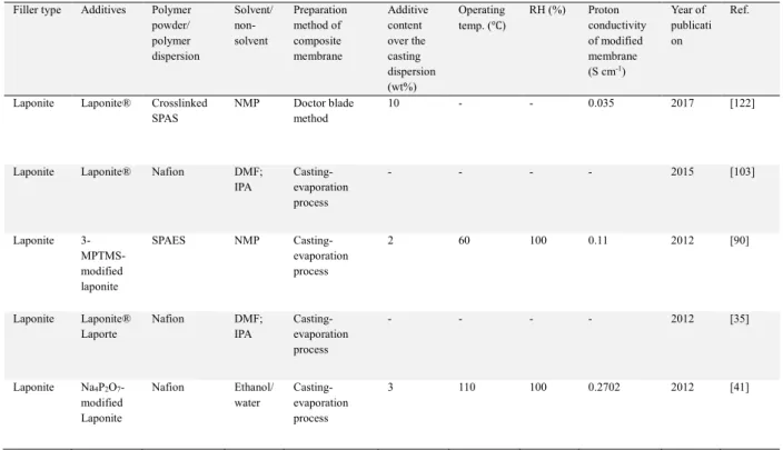
3.3. Effect of Laponite® (synthetic Hectorite-like clay) type additive ………. 68
3.3.1. Pristine Laponite additive ……….…..……… 69
3.3.2. Sulfonated Laponite additive ………..………… 71
3.3.3. Other types of Laponite additive ……….…… 74
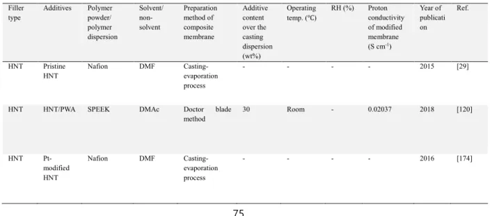
3.4. Effect of halloysite type additive ……….…..… 75
3.4.1. Pristine HNT additive ………..……… 76
3.4.3. Aminized HNT additive ………..…… 79
3.4.4. Other type of HNT additive ……… 79
3.5. Effect of sepiolite type additive ……….…… 80
3.5.1. Pristine SEP additive ………..……….………… 81
3.5.2. Sulfonated SEP additive ……….………. 81
3.5.3. Perfluorosulfonated SEP additive ……….…... 83
Conclusions ………...………. 85
Chapter 2. Experimental and characterization methods ……….….………….……….… 87
Summary ………...….…… 88 Résumé ……….…..…… 88 1. Materials ……….…...…… 89 2. Experimental methods ……….….……… 89 2.1. Sepiolite modification ……….…….….…….. 89 2.2. Halloysite modification ……….…….……… 89
2.3. Filtration and acidic pretreatment of nanoclays ……….……… 90
2.3.1. Filtration ……….….…..……… 90
2.3.2. Pretreatment ………..…… 90
2.4. Membrane preparation ……….….…… 90
2.4.1. Nafion-based composite membranes.……… 91
2.4.2. Aquivion-based composite membranes ……….………… 92
3. Analytical methods ……… 94
3.1. ATR-FTIR ……….……… 94
3.2. TGA ……….………...….. 94
3.3. Py-GC/MS ……… 94
3.4. FE-SEM and EDS ……… 94
3.5. Membrane thickness ……….………… 94
3.6. Water uptake ……….………… 95
3.7. Swelling ratio ………...… 95
3.8. IEC (ion exchange capacity) ………..……….. 95
3.9. Chemical stability ………....….… 95
3.10. EIS (electrochemical impedance spectroscopy) .………..…..… 96
3.11. DMA (dynamic mechanical analysis) ………...………...…..… 97
3.12. MEA preparation ……… 97
3.13. Single cell set-up and test protocols ………...… 97
Chapter 3. Effect of blending time on composite homogeneity ………..………..……….…. 99
Summary ……….………..…….… 100
Résumé ………..….… 100
1. Introduction ………...………… 101
2. Preparation of Nafion-based composite membranes ……….… 101
3. Composite homogeneity of Nafion electrolyte membranes………..…..… 102
4. Water uptake ……….……… 105
5. Swelling ratio and ion exchange capacity ………...……… 106
Conclusions ……… 107
Chapter 4. Influence of fluorinated, sulfonated and perfluorosulfonated - pretreated halloysites on electrolyte membranes ..……….………..…………..………...……....…. 109
Summary ……… 110
Résumé ………...… 111
1. Introduction ……….………..… 113
2. Membrane preparation ……… 113
3. Nanoclay functionalization and characterization ………..… 114
3.1. Functionalization of halloysites ………... 114
3.1.1. Fluorinated halloysite (HNT-F) ………...……….…… 114
3.1.2. Sulfonated halloysite (HNT-S) ……….….… 115
3.1.3. Perfluoro-sulfonated halloysite (HNT-SF) ……….….….. 115
3.2. Characterization of halloysites (ATR-FTIR, TGA, Py-GC/MS) ……….. 116
4. Membrane characterization ……….… 119
4.1. Thickness of hydrated membranes (micrometer) ……….……… 119
4.2. Ion exchange capacity ………..… 120
4.3. Water uptake ……….… 121
4.4. Swelling ratio ………... 122
4.5. Homogeneity of composite membranes (FE-SEM and EDS) ……….. 123
4.6. Dynamic mechanical analysis (DMA) ……….… 124
4.7. Chemical stability ……….… 126
4.8. Proton conductivity (EIS) ……….……… 128
Conclusions ……… 132
Chapter 5. Quercetin grafting effect of anti-oxidative activity on electrolyte membranes …………... 133
Summary ……….…… 134
Résumé ……….…… 135
1. Introduction ……….……… 137
2. Membrane preparation ………...………… 138
3. Nanoclay fuctionalization and characterization ………...……… 139
3.1.1. Grafting of halloysite with quercetin (HNT-Q) ……….. 139
3.1.2. Grafting of halloysite with quercetin and fluorinated groups (HNT-FQ) ………..…. 139
3.1.3. Grafting of halloysite with quercetin and amino groups (HNT-NQ) ……….……. 139
3.2. Chracterization of functionalized halloysites (ATR-FTIR, TGA, Py-GC/MS) …….……….…… 140
4. Membrane characterization ………..………. 143
4.1. Homogeneity of composite membranes (FE-SEM and EDS) ……… 143
4.2. Thickness of hydrated membranes (micrometer) ………...………… 144
4.3. IEC ……….… 145
4.4. Water uptake ………...…… 146
4.5. Swelling ratio ……….… 147
4.6. Chemical stability ………...…… 148
4.7. Proton conductivity (EIS) ……….…..… 150
Conclusions ………..… 152
Chapter 6. Impact of fluorinated and pretreated sepiolite on electrolyte membrane …………..….…. 153
Summary ……… 154
Résumé ………...… 155
1. Introduction ………...……… 157
2. Sepiolite functionalization ……… 157
3. Sepiolite characterization (ATR-FTIR, TGA, and Py-GC/MS) ……… 158
4. Membrane preparation ……….……… 160
5. Membrane characterization ……….……… 161
5.1. Homogeneity of composite membranes (FE-SEM and EDS) ……….….……… 161
5.2. Thickness of hydrated membranes (micrometer) ……….………… 163
5.3. IEC ………...…… 164
5.4. Water uptake ………...……….. 164
5.5. Swelling ratio ………..………. 165
5.6. Dynamic mechanical analysis (DMA) ………. 167
5.7. Chemical stability ………...….. 168
5.8. Proton conductivity (EIS) ………. 169
5.9. Impact of the acidic treatment on nanoclays ……… 172
5.10. Fuel cell performances ………...… 175
Conclusions ………...……. 177
Conclusions and perspectives …………...……… 179
1. Summary ………..….. 180
2. Achievements ……….…… 181
2.1. Influence of blending time of halloysite or sepiolite inside Nafion membranes ………. 181
2.2. Effect of halloysite or sepiolite filler incorporating into Aquivion composite membranes ………. 181
2.4. Impact of quercetin grafting on Aquivion composite membranes ………... 182 2.5. Effect of pretreated nanoclays and their various contents on Aquivion composite membranes ….. 182
3. Perspectives ……… 183 Annex ... 185 Bibliography ………..…… 195 Abstract Keywords Résumé Mots clés
Abbreviation
[BVBI][Cl], 1-butyl-3-(4-vinylbenzyl)imidazolium chloride; [HMIM][Cl], 1-hexyl-3-methylimidazolium chloride; [TMG][BF4], 1,1,3,3-tetramethylguanidine tetrafluoroborate; 1,3-PS, 1,3 propane sultone
1,4-BS, 1,4 butane sultone
3-MPTMS, 3-(mercaptopropyl)trimethoxysilane; AAc, acrylic acid;
ABPBI, poly(2,5-benzimidazole);
ACA, 6-aminocaproic acid; BHB, behenyl betaine; AFC, alkaline fuel cell;
AIBN, 2,2′-azobisisobutyronitrile;
AMPS, 2-acrylamido-2-methyl-1-propanesulfonic acid; AP, anionic polymerization;
ATRP, atom transfer radical polymerization; BCPS, bis-(4-chlorophenylsulfone); BMC, bulk molding compound; CS, chitosan;
CTAB, cetyltrimethylammonium bromide; CTAC, hexadecyltrimethylammonium chloride; DABA, 3,4-diaminobenzoic acid;
DCDPS, 4,4’-dichlorodiphenyl sulfone; DFB, 4,4’-diflluorobenzophenone; DMA, dynamic mechanical analysis; DMAc, dimethylacetamide;
DMDOC, dimethyl dioctadecylammonium chloride; DMF, N,N-dimethylformamide;
DMOSPA, dimethyloctadecyl(3-sulfopropyl) ammonium hydroxide; DMSO, dimethyl sulfoxide;
DOA, dodecylamine;
EDS, energy-dispersive X-ray spectroscopy;
EHTES, 2(3, 4 epoxy cyclo hexyl)ethyltriethoxy silane; FE-SEM, field emission scanning electron microscopy
FMES, 1,2,2-tri-fluoro-hydroxy-l-trifluomethylethane sulfonic acid sultone GA, glutaraldehyde;
GPTMS, 3-glicidoxy propyltrimethoxysilane; HDDA, hexanediol diacrylate;
HDTMA, hexadecyltrimethylammonium; HEMA, 2-hydroxyethyl methacrylate; HNT, halloysite nanotube;
IEC, ion exchange capacity; IPA, isopropyl alcohol;
MCFC, molten carbonate fuel cell; MEA, membrane electrode assembly; MMT, montmorillonite;
MPS, propyltrimethoxysilan;
MWNT, multi-walled carbon nanotube; NaSS, sodiumstyrene sulfonate; NMP, 1-methyl-2-pyrrolidinone; PAFC, phosphoric acid fuel cell; PBI, polybenzimidazole;
PBP, 4,40-(1,4-phenylene diisopropylidene)bisphenol; PEG, polyethylene glycol;
PEM, proton exchange membrane;
PEMFC, proton exchange membrane fuel cell; PEO, poly(ethylene oxide);
PES, poly(ether sulfones);
PFPE-NR3, quaternized ammonium perfluoropolyether; PFSA, perfluorosulfonic acid;
PFSI, perfluorosulfonate ionomer; pHNT, pretreated halloysite nanotube;
pHNT-F, pretreated and fluorinated halloysite nanotube;
pHNT-FQ, pretreated and fluorinated-quercetin-grafted halloysite nanotube; pHNT-NQ, pretreated and aminized-quercetin-grafted halloysite nanotube; pHNT-S, pretreated and sulfonated halloysite nanotube;
pHNT-SF, pretreated and perfluorosulfonated halloysite nanotube; pHNT-Q, pretreated and quercetin-grafted halloysite nanotube; POPD, poly(oxyproplene)-backboned diamine cation; PPA, polyphosphoric acid;
PPA, polyphosphoric acid; PPO, poly(p-phenylene oxide); PSA, phenylsulfonic acid; pSEP, pretreated sepiolite;
pSEP-F, pretreated and fluorinated sepiolite; PSSA, poly(styrene sulfonic acid);
PSU, polysulfone;
PVOH, poly(vinyl alcohol); PWA, Phosphotungstic acid; RH, relative humidity;
RIP, radiation-induced polymerization; ROP, ring opening polymerization; RP, radical polymerization; SEP, sepiolite nanofiber;
SFRP, stable free radical polymerization; SOFC, solid oxide fuel cell;
SPAES, sulfonated poly(arylene ether sulfonate); SPAS, sulfonated poly(arylene sulfone);
SPEEK, sulfonated poly(ether ether ketone); SPEK, poly(ether ketone);
SPPESK, sulfonated poly(phthalazinone ether sulfone ketone);
SPSEBS, sulfonated polystyrene block-poly(ethylene-ran-butylene)-block-polystyrene; SPSU, sulfonated polysulfone;
SPSU-BP, sulfonated poly (biphenyl ether sulfone);
SSEBS, (Sulfonated poly(styrene-b-ethylene/butylene-b-styrene); St, styrene;
STA, silicotungstic acid; TAP, 2,4,6-triaminopyrimidine; TGA, thermal gravimetric analysis; TMSCS, trimethyl silyl chlorosulfonate.
List of figures
Fig. 1. Electrochemical combustion of hydrogen fuel cell: (a) H2 molecules split into hydrogen atoms at anode. (b)
A catalyst allows the hydrogen atoms to split into hydrogen ions (H+) and electrons. (c) At cathode, oxygen reacts
with hydrogen ions (H+) and electrons to form pure water molecules ……….………...…… 26
Fig. 1.1. Structure of unmodified montmorillonite nanoclay (trade name: Cloisite Na+) ……… 36
Fig. 1.2. Typical dispersion state of polymer/layered nanoclay composites: (a) no chain penetration (i.e.,
micro-composite), (b) chain intercalation, and (c) nanoclay exfoliation (i.e., nanocomposite) ……….….…… 37
Fig. 1.3. Images on (a) Laponite chemical formula, (b) Laponite structure, and (c) single Laponite crystal
………..….. 37
Fig. 1.4. Schematic diagram concerning structure of sepiolite nanofiber ……….…… 38 Fig. 1.5. Schematic representation regarding (a) crystalline structure and (b) structure of halloysite nanotube
……….……... 39
Fig. 1.6. Appearance example of membrane electrode assembly (MEA) prepared using hot pressing process .. 41 Fig. 1.7. Grafting reaction of (a) one-step and (b) two-step methods ………...…… 42
Fig. 1.8. Schematic diagram of three kinds of vinyl polymer/Cloisite Na+ nanocomposite prepared by
radiation-induced polymerization ……….………… 45
Fig. 1.9. (a) Photo image and (b) scheme of the experimental device for membrane prepared under electric field
……….……….……….. 46
Fig. 1.10. Proton conductivity of pristine PVOH, PVOH/Cloisite Na+ and PVOH/Cloisite Na+/phosphotungstic
acid membranes ….……… 47
Fig. 1.11. Synthetic illustration of (up) [HMIM][Cl] and (down) [TMG][BF4] ionic liquids ………..…… 48
Fig. 1.12. Polymerization process of ABPBI in mixture containing P2O5 and methanesulfonic acid
………..…………..… 48
Fig. 1.13. Sulfonation process of SSEBS, which was reacted with acetyl sulfate and SEBS ………..…… 49 Fig. 1.14. TEM morphology of (a) thick stacks of pure SEBS/MMT (4 wt%) composite membrane, (b)
intercalated-exfoliated membrane composed of sulfonated SEBS (3 wt%)/MMT (4 wt%) and (c) exfoliated membrane composed of sulfonated SEBS (6 wt%)/MMT (4 wt%) membranes ……….. 49
Fig. 1.15. Schematic illustration of vinyl group functionalized polymer/Na+-MMT/[BVBI][Cl] composite
Fig. 1.16. Schematic diagram of three kinds of vinyl polymer/Cloisite Na+ nanocomposite prepared by
radiation-induced polymerization ……….…… 50
Fig. 1.17. Synthesis process of HSO3-R-MMT and HSO3-RSR-MMT ………..……..… 51
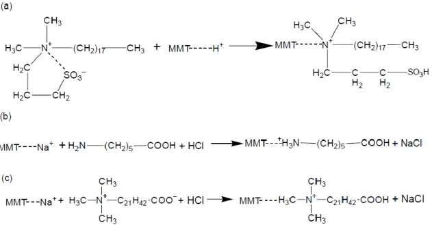
Fig. 1.18. Schematic representation of the ammonium cations synthesized with the cation exchange with MMT: (a) dimethyloctadecyl(3-sulfopropyl) ammonium (hydroxide) (DMOSPA), (b) 6-aminocaproic acid (ACA), and (c) behenyl betaine (BHB) ………..………..………… 52
Fig. 1.19. Schematic structure of functionalization procedure for 1,4-BS-modified MMT, 1,3-PS-modified MMT and FMES-modified MMT ………... 52
Fig. 1.20. Synthesis process of POPD400 and POPD400-PS ……….……….……… 53
Fig. 1.21. Preparation process of Nafion/dodecylamine-exchanged MMT composite membranes ………. 54
Fig. 1.22. Synthetic process of sulfonated MMT ………...………..……. 55
Fig. 1.23. Proton conductivity of Nafion117 (◆) and pristine SPEEK (+) membranes. Proton conductivity of SPEEK composite membrane containing 1wt% (○), 3wt% (△) and 5wt% (□) of unmodified MMT; and containing 1wt% (●), 3wt% (▲) and 5wt% (■) of sulfophthalic acid-modified MMT ………..…….………….. 56
Fig. 1.24. Synthetic process of STA-modified MMT (left) and SPSU-BP (right) ………...…….… 57
Fig. 1.25. Schematic diagram of sulfonated MMT synthesized with 3-MPTMS and toluene ………. 58
Fig. 1.26. Chemical structure of (a) PFPE-NR3 (x = y = 14) and (b) Zonyl (n = ±5) ……….. 58
Fig. 1.27. Modification process of MMT synthesized with Krytox and Nafion ……….. 59
Fig. 1.28. Flexural strength (MPa) of vinyl ester composite membranes containing pristine MMT; and POPD230-, POPD400- and POPD2000-modified MMT ………..………...…… 61
Fig. 1.29. Data on (a) proton conductivity (under ambient temperature) of pristine Nafion membrane made by extruding and recasting, and (b) proton conductivity (under room temperature and dry state) of Nafion/Cloisite 15A composite membrane according to filler loading ………..……… 61
Fig. 1.30. Cross-linking process of 1,4-bis (hydroxymethyl) benzene (BHMB) cross-linked SPEEK…………. 63
Fig. 1.31. Proton Conductivity of PVOH composite membranes according to the content of phosphotungstic acid and Cloisite Na+ ………..……….…….…. 65
Fig. 1.32. Synthetic procedure of silane-based composite membranes by sol-gel method ... 66
Fig. 1.34. Proton conductivity of Nafion/unmodified MMT, Nafion/Cloisite 15A and Nafion/CS-modified MMT
composite membranes ……….……….. 68
Fig. 1.35. Self-diffusion coefficients based on different temperature and laponite loadings within composite
membrane prepared using DMF ………...………. 70
Fig. 1.36. Modification process of sulfonated Laponite synthesized with (a) p-styrene sulfonic acid sodium salt
and (b) 1,3-propane sultone sodium salt ………... 71
Fig. 1.37. Proton conductivity of (a) commercial Nafion – NRE212, (b) commercial Nafion – NRE211, (c)
Nafion/p-styrene sulfonate-grafted Laponite and (d) Nafion/1,3-propane sultone-grafted Laponite composite membranes ……….……….………..………...……. 72
Fig. 1.38. Proton conductivity of the membranes measured under condition of 25℃ and various relative humidity:
(○) Nafion 115, (■) Nafion/unmodified Laponite and (■) Nafion/styrene sulfonic-grafted Laponite membranes ……….…...……… 72
Fig. 1.39. Synthesis procedure of sulfonated Laponite ………. 73 Fig. 1.40. Water uptake of pristine Nafion, pristine SPAES, SPAES/Laponite and SPAES/3-MPTMS-modified
laponite membranes ………..……… 73
Fig. 1.41. Proton conductivity of (a) pristine Nafion (i.e., N0), (b) Nafion/Na4P2O7-activated Laponite (i.e., NxUL
series) and (c) H3PO4-activated Laponite (i.e., NxAL series) membranes ………..………..……… 74
Fig. 1.42. Data on proton conductivity of SPEEK/sulfonated HNT composite membrane measured at 100% RH
………..…….……… 77
Fig. 1.43. Proton conductivity of SPEEK/HNT, SPEEK/dopamine-modified HNT and SPEEK/SSA-modified
HNT membranes ………..………. 78
Fig. 1.44. Temperature-dependent conductivity of CS, CS/SPNF and CS/SPNF/MPS-modified HNT composite
membrane measured at 100% RH ……… 78
Fig. 1.45. Temperature-dependent conductivity of SPEEK, SPEEK/unmodified HNT and
SPEEK/dopamine-modified membranes ………...………. 79
Fig. 1.46. Schematic illustration of (a) the prepared electrospun mat, (b) the compressed membrane, and (c) the
hot-pressed membrane. Synthesis process of (d) SPEK and (e) non-sulfonated PES ………. 81
Fig. 1.47. Structure of SEP functionalized with sulfonic acid ………. 82 Fig. 1.48. Polarization curves obtained during MEA test of (a) pristine Nafion (i.e., M112), (b) Nafion/SEP (i.e.,
M112S10), and (c) Nafion/SSA-modified SEP (i.e., M112S10SH) membranes measured at 75℃ (solid lines) and 100℃ (dashed lines), between 25 and 100% RH ………..…..……… 82
Fig. 1.49. Perfluorosulfonated SEP, which introduces –SO3H and –C7F15 groups ………..………. 84
Fig. 1.50. Polarization curves of pristine Nafion (dotted lines) and Nafion/sulfo-fluorinated SEP membranes (solid
lines) measured at 75 °C and 100 °C between 25% RH and 75% RH ………..………..……... 84
Fig. 2.1. Photo of (a) oven and (b) mold used for casting the membrane.……….… 91 Fig. 2.2. Photo of the ultrasound equipment (HD 2070, Bandelin, Germany)used to disperse nanoclay in the casting
dispersion ………..……….……… 92
Fig. 2.3. Photo of wet membrane detached from glass plate ……… 92 Fig. 2.4. Photo images on (a) electrochemical impedance spectroscopy (EIS) equipment, (b) appearance of
proprietary cell, and (c) inner part of proprietary cell ……….…..…… 96
Fig. 3.1. Photo images of the ultrasound equipment used to disperse nanoclay in the casting dispersion (reproduced
from chapter 2) ……… 102
Fig. 3.2. Photo images of pristine Nafion blended for (a) 24h, (d) 5h, (g) 1h, Nafion/SEP blended for (b) 24h, (e)
5h, (h) 1h, and Nafion/HNT blended for (c) 24h, (f) 5h, (i) 1h ………...……… 103
Fig. 3.3. Thickness of membranes with respect of blending time, measured under wet condition: pristine Nafion,
and SEP- or HNT-based composite membranes ……….…….…... 103
Fig. 3.4. Cross sectional images of (a, c) Nafion/SEP-24h, (b, d) Nafion/HNT-24h, (e) Nafion/SEP-5h, (f)
Nafion/HNT-5h, (g) Nafion/SEP-1h and (h) Nafion/HNT-1h membranes observed using FE-SEM. Reprinted with permission from international conference on power and energy engineering (Abstract of proceedings) and CSJ journals ………..…….………… 104
Fig. 3.5. Si/F atomic ratio (%) of pristine Nafion, Nafion/SEP and Nafion/HNT composite membranes analyzed
using EDS ………... 105
Fig. 3.6. Data on (a) water uptake, (b) swelling ratio and (c) IEC regarding pristine Nafion and composite
membranes incorporated with SEP and HNT ……….……… 106
Scheme 4.1. Schematic representation of halloysite nanotubes (a) fluorinated, (b) sulfonated, and (c)
perfluorosulfonated ………...….. 115
Fig. 4.1. ATR-FTIR spectra of (a, e) pristine halloysite, (b, f) HNT-F, (c, g) HNT-S and (d) (h) HNT-SF ..…. 116 Fig. 4.2. TGA under nitrogen of pristine halloysite, HNT-F, HNT-S and HNT-SF samples from 110 °C to 900 °C
after an isotherm at 110 °C for 10 min ……… 117
Fig. 4.3. Py–GC/MS chromatograms obtained for (a) HNT-F, (b) HNT-S and (c) HNT-SF samples pyrolyzed at
Fig. 4.4. Data on thickness: commercially available Nafion HP and Gore Select M820, and pristine Aquivion and
Aquivion composite membranes containing various halloysites, HNT, HNT-F, HNT-S and HNT-SF. Yellow and blue bars represent non-pretreated and pretreated nanoclays, respectively ………..……….. 119
Fig. 4.5. Data on ion exchange capacity: commercially available Nafion HP and Gore Select M820, and pristine
Aquivion and Aquivion composite membranes containing various halloysites, HNT, HNT-F, HNT-S and HNT-SF. Yellow and blue bars represent non-pretreated and pretreated nanoclays, respectively …….………..………. 120
Fig. 4.6. Data on water uptake: commercially available Nafion HP and Gore Select M820, and pristine Aquivion
and Aquivion composite membranes containing various halloysites, HNT, HNT-F, HNT-S and HNT-SF. Yellow and blue bars represent non-pretreated and pretreated nanoclays, respectively ………..………… 121
Fig. 4.7. Data on swelling ratio: commercially available Nafion HP and Gore Select M820, and pristine Aquivion
and Aquivion composite membranes containing various halloysites, HNT, HNT-F, HNT-S and HNT-SF. Yellow and blue bars represent non-pretreated and pretreated nanoclays, respectively ……….. 122
Fig 4.8. FE-SEM images regarding (a) commercially available Nafion HP, (b) Gore Select M820, (c) pristine
Aquivion, and (d - s) Aquivion composite membranes blended with HNT, HNT-F, HNT-S and HNT-SF ……….. 123
Fig. 4.9. Si/F atomic ratio calculated from EDS measurements, regarding commercially available Nafion HP, Gore
Select, pristine Aquivion, and Aquivion composite membranes incorporated with HNT, F, S and HNT-SF. Yellow and blue bars represent non-pretreated and pretreated nanoclays, respectively ……….…….……… 124
Fig. 4.10. DMA results on G’ & G’’ of composite membranes containing 10wt% of (a) non-pretreated and (b)
pretreated HNTs. DMA data on tan delta of electrolyte membranes blended with 10wt% of (c) non-pretreated and (d) pretreated HNT ………..…………...… 125
Fig. 4.11. DMA tests performed under different relative humidity (RH%) from 15 to 65% for (a) Nafion HP, (b)
pristine Aquivion, (c) Aq/HNT10, (d) Aq/HNT-F10, (e) Aq/HNT-S10 and (f) Aq/HNT-SF10 ……….…… 126
Fig. 4.12. Fluoride (F-) concentration analyzed after immersion in H
2O2/H2SO4 for Nafion HP, Gore Select M820,
pristine Aquivion, Aq/HNT, Aq/HNT-F, Aq/HNT-S, Aq/HNT-SF, Aq/pHNT, Aq/pHNT-F, Aq/pHNT-S and Aq/pHNT-SF membranes. Red dotted line represents the fluorine concentration of 4.4 M H2O2/1.25 mM H2SO4
solution (blank test): 0.82×10⁻⁴ ± 0.08×10⁻⁴ mol/L ……… 127
Fig. 4.13. Comparison of Fe/Si atomic ratio (%) regarding HNT, pHNT, HNT-F, pHNT-F, HNT-SF, pHNT-SF,
HNT-S and pHNT-S clay nanotubes used for preparing composite membranes.Yellow and blue represent non-pretreated and non-pretreated nanoclays, respectively ………. 127
Fig. 4.14. Proton conductivity comparison of non-pretreated and functionalized vs. pretreated and functionalized
nanoclays on composite membranes under various temperature and relative humidity: Nafion HP, Gore Select M820, pristine Aquivion, Aquivion/HNT, Aquivion/HNT-F, Aquivion/HNT-S, Aquivion/HNT-SF, Aquivion/pHNTs, Aquivion/pHNTs-F, Aquivion/pHNTs-S and Aquivion/pHNTs-SF composite membranes incorporated with 10wt% contents ……….……… 129
Fig. 4.15. Influence of temperature and relative humidity on proton conductivity (mS/cm) for various PEMs:
Nafion HP, Gore Select, pristine Aquivion, Aquivion/HNT, F, S, Aquivion/HNT-SF, Aquivion/pHNTs, Aquivion/pHNTs-F, Aquivion/pHNTs-S and Aquivion/pHNTs-SF composite membranes incorporated with 10wt%, 5wt% and 2wt% contents ………...….. 131
Fig. 5.1. Chemical structure of quercetin used for grafting ……… 137 Scheme 5.1. Schematic representation of halloysite nanotubes grafted with (a) quercetin, (b) quercetin/fluorinated
groups, and (c) quercetin/amino groups ………..………... 139
Fig. 5.2. ATR-FTIR spectra of (a) (e) pristine halloysite, (b) (f) HNT-Q, (c) (g) HNT-FQ and (d) (h) HNT-NQ
………..……… 140
Fig. 5.3. TGA under nitrogen of HNT, HNT-Q, HNT-FQ and HNT-NQ samples from 110 °C to 900 °C after an
isotherm at 110 °C for 10 min ……….…… 141
Fig. 5.4. Py–GC/MS chromatograms obtained for (a) HNT-Q, (b) HNT-FQ and (c) HNT-NQ samples pyrolyzed
at 900°C ………..…… 142
Fig. 5.5. FE-SEM images regarding (a) commercially available Nafion HP, (b) Gore Select M820 (Aquivion), (c)
pristine Aquivion, and (d – s) composite membranes blended with HNT, HNT-Q, HNT-FQ and HNT-NQ ………..……… 143
Fig. 5.6. Si/F atomic ratio verified using EDS regarding commercially available Nafion HP, Gore Select
(Aquivion), pristine Aquivion, and Aquivion composite membranes incorporated with HNT, HNT-Q, HNT-FQ and HNT-NQ. Yellow and blue bars represent non-pretreated and pretreated nanoclays, respectively ……….………… 144
Fig. 5.7. Data on thickness: commercially available Nafion HP and Gore Select M820, and pristine Aquivion and
Aquivion composite membranes containing quercetin-grafted halloysites. Yellow and blue bars represent non-pretreated and non-pretreated nanoclays, respectively ………..………. 145
Fig. 5.8. Data on ion exchange capacity: commercially available Nafion HP and Gore Select M820, and pristine
Aquivion and Aquivion composite membranes containing quercetin-grafted halloysites. Yellow and blue bars represent non-pretreated and pretreated nanoclays, respectively ... 146
Fig. 5.9. Data on water uptake: commercially available Nafion HP and Gore Select M820, and pristine Aquivion
and Aquivion composite membranes containing quercetin-grafted halloysites. Yellow and blue bars represent non-pretreated and non-pretreated nanoclays, respectively ... 147
Fig. 5.10. Data on swelling ratio: commercially available Nafion HP and Gore Select M820, and pristine Aquivion
and Aquivion composite membranes containing quercetin-grafted halloysites. Yellow and blue bars represent non-pretreated and non-pretreated nanoclays, respectively ... 148
Fig. 5.11. Fluoride (F-) concentration analyzed after immersion in H2O2/H2SO4 for Nafion HP, Gore Select M820
(Aquivion), pristine Aquivion, Aq/HNT, Aq/HNT-Q, Aq/HNT-FQ, Aq/HNT-NQ, Aq/pHNT, Aq/pHNT-Q, Aq/pHNT-FQ and Aq/pHNT-NQ membranes. Red dotted line represents the fluorine concentration of 4.4 M H2O2/1.25 mM H2SO4 solution (blank test): 0.82×10⁻⁴ ± 0.08×10⁻⁴ mol/L ……… 149
Fig. 5.12. Comparison of Fe/Si atomic ratio (%) regarding HNT, pHNT, HNT-Q, pHNT-Q, HNT-FQ, pHNT-FQ,
HNT-NQ and pHNT-NQ nanoclays used for preparing composite membranes. Yellow and blue bars represent non-pretreated and non-pretreated nanoclays, respectively ……….……….. 149
Fig. 5.13. Influence of temperature (a) 50℃, (b) 70℃ and (c) 90℃, and relative humidity on proton conductivity
(mS/cm) for various PEMs: Nafion HP, Gore Select (Aquivion), pristine Aquivion, Aquivion/HNT, Aquivion/HNT-Q, Aquivion/HNT-FQ, Aquivion/HNT-NQ, Aquivion/pHNTs, Aquivion/pHNTs-Q, Aquivion/pHNTs-FQ and Aquivion/pHNTs-NQ composite membranes incorporated with 2, 5 and 10 wt% contents ...……….………….. 151
Scheme 6.1. Schematic representation of sepiolite nanofiber perfluorination grafted with
N-(3-triethoxysilylpropyl)-perfluorooctanoamide (SPFOA) ………... 157
Fig. 6.1. ATR-FTIR spectra of (a) pristine sepiolite and (b) functionalized sepiolite ………...………. 158 Fig. 6.2. TGA under nitrogen of pristine sepiolite and fluorine grafted sepiolite from 110 °C to 900 °C after an
isotherm at 110 °C for 10 min ……….……… 159
Fig. 6.3. Py–GC/MS chromatograms obtained for modified sepiolite sample pyrolyzed at 900°C ………...… 159 Fig. 6.4. FE-SEM images on (a) commercially available Nafion HP, (b) Gore Select (Aquivion), (c) pristine
Aquivion, (d) Aq/SEP10, (e) Aq/pSEP10, (f) Aq/pSEP5, (g) Aq/SEP2, (h) Aq/SEP-F10, (ih) Aq/pSEP-F10, and (j) Aq/pSEP-F5 and (k) Aq/pSEP-F2 membranes ...……….…… 161
Fig. 6.5. Si/F atomic ratio (%) analyzed using EDS regarding sepiolite-based membranes: Aq/SEP10, Aq/pSEP5,
Aq/pSEP2, Aq/pSEP10, Aq/SEP-F10, Aq/pSEP-F5, Aq/pSEP-F2 and Aq/pSEP-F10. Yellow and blue bars represent non-pretreated sepiolites and pretreated sepiolites, respectively. The different patterns represent different additive contents ..………...……….…… 162
Fig. 6.6. Thickness, IEC, water uptake and swelling ratio of commercially available Nafion HP and Gore Select,
and pristine Aquivion and Aquivion composite membranes containing various sepiolites. Gray bars represent referece membranes. Yellow and blue bars represent non-pretreated sepiolites and pretreated sepiolites, respectively. The diagonal line patterns represent fluorinated sepiolites ... 163
Fig. 6.7. IEC of commercially available Nafion HP and Gore Select, and pristine Aquivion and Aquivion composite
membranes containing various sepiolites. Gray bars represent referece membranes. Yellow and blue bars represent non-pretreated sepiolites and pretreated sepiolites, respectively. The diagonal line patterns represent fluorinated sepiolites ...………..….……… 164
Fig. 6.8. Water uptake of commercially available Nafion HP and Gore Select, and pristine Aquivion and Aquivion
composite membranes containing various sepiolites. Gray bars represent referece membranes. Yellow and blue bars represent non-pretreated sepiolites and pretreated sepiolites, respectively. The diagonal line patterns represent fluorinated sepiolites ………..……… 165
Fig. 6.9. Swelling ratio of commercially available Nafion HP and Gore Select, and pristine Aquivion and Aquivion
composite membranes containing various sepiolites. Gray bars represent referece membranes. Yellow and blue bars represent non-pretreated sepiolites and pretreated sepiolites, respectively. The diagonal line patterns represent fluorinated sepiolites ..……….………..……….. 166
Fig. 6.10. Data on DMA - (a) G’ and (b) tan delta - concerning Nafion HP, Gore-Select M820, pristine Aquivion,
and Aquivion composite membranes blended with sepiolite and pretreated sepiolite ……… 167
Fig. 6.11. Fluoride (F-) concentration analyzed after immersion in H2O2/H2SO4 for Nafion HP, Gore Select
(Aquivion), pristine Aquivion, Aq/SEP, Aq/SEP-F, Aq/pSEP and Aq/pSEP-F membranes. Red dotted line represents the fluorine concentration of 4.4 M H2O2/1.25 mM H2SO4 solution (blank test): 0.82×10⁻⁴ ± 0.08×10⁻⁴
mol/L ...………..………….. 168
Fig. 6.12. 3D cylinder graphs depending on temperature (50℃, 70℃, and 90℃) regarding proton conductivity of
various PEMs: (a) Nafion HP, (b) Gore Select (Aquivion), (c) pristine Aquivion, (d) Aquivion/SEP10, (e) Aquivion/pSEP10, (f) Aquivion/pSEP5, (g) Aquivion/SEP-F10, (h) F10, and (i) Aquivion/pSEP-F5 membranes ……….……… 170
Fig. 6.13. Influence of temperature (a) 50℃, (b) 70℃, (c) 90℃ and relative humidity on proton conductivity for
various PEMs: Nafion HP, Gore Select (Aquivion), pristine Aquivion, Aquivion/SEP10, Aquivion/pSEP5, Aquivion/pSEP10, Aquivion/SEP-F10, Aquivion/pSEP-F2, Aquivion/pSEP-F5, and Aquivion/pSEP-F10 membranes ………..…… 171
Fig. 6.14. XRD pattern of pretreated sepiolites: SEP (black), SEP-F (red), pSEP (blue) and pSEP-F (green)
nanoclays used for preparing composite membranes ………..…… 173
Fig. 6.15. Comparison of (a) Mg/Si, (b) Fe/Si and (c) Al/Si atomic ratio (%) regarding SEP, pSEP, SEP-F, and
pSEP-F nanoclays used for preparing composite membranes ………..…….. 173
Fig. 6.16. Diffusion coefficient of water molecules and protons to (a) sepiolite and (b) pretreated sepiolite. The
water molecules diffuse relatively easily to swelled sepiolite, which makes the ionic mobility easier ……..… 174
Fig. 6.17. Polarization curves of membrane electrode assemblies (MEAs) based on Nafion HP and different
Fig. 6.18. Evolution of (a) the voltage at 0.6 A/cm² and (b) the hydrogen crossover for the different MEAs during
List of tables
Table 1.1. Properties of Nafion HP, Gore Select EW1100 and Gore Select EW900 …..……….. 33 Table 1.2. Thermal and mechanical stability of various polymers used as fuel cell membrane …………..……. 34
Table 1.3. Properties of Cloisite Na+, Cloisite 10A, Cloisite 15A, Cloisite 20A, Cloisite 30B, Cloisite 93A
manufactured by Southern Clay Products Inc ………...………… 40
Table 1.4. Summary data on membrane casting dispersions composed of Laponite and ionomer, and proton
conductivity of prepared membranes ………...…. 68
Table 1.5. Summary data on membrane casting dispersions composed of halloysite and ionomer, and proton
conductivity of prepared membranes ……… 75
Table 1.6. Summary data on membrane casting dispersions composed of sepiolite and ionomer, and proton
conductivity of prepared membranes ……… 80
Table 2.1. Chemical compositions of Nafion casting dispersions with sepiolite or halloysite ………….…...…. 91 Table 2.2. Information on nineteen different kinds of membranes prepared based on the available nanoclays
……… 93
Table A1. Summary data on membrane casting dispersions composed of montmorillonite and ionomer, and proton
1. Background
The increasing amount of greenhouse gas, e.g., carbon dioxide (CO2), released in the atmosphere due to the
consumption of fossil fuels is causing climate change. Hence, Earth has been suffering from climate change during 20th century because CO2 gas resulted in global warming impacting Earth’s surface and the lower atmosphere.
Greenhouse effect has a negative influence and change of sea level, precipitation pattern, glacier retreat, and agricultural yields. Accordingly, an attempt to reduce CO2 gas emissions is necessary for humankind and all living
creatures [1, 2].
One eco-friendly alternative to energy conversion from fossil fuels is the fuel cell. The fuel cell is a useful electrochemical device which converts chemical energy from various fuels to electrical energy and heat. This is an environmental-friendly solution in lieu of alleviating carbon dioxide emission from combustion and it will have a positive impact on the climate change. In general, fuel cells include proton exchange membrane fuel cell (PEMFC), solid oxide fuel cell (SOFC), phosphoric acid fuel cell (PAFC), alkaline fuel cell (AFC) and molten carbonate fuel cell (MCFC). Depictions of the various fuel cells were described in the literatures [3, 4]. In particular, PEMFC is attractive in the field of automobile application due to low operating temperature, high efficiency, portable power generation, high power density, and innocuous electrolyte, which is a hydrated proton conducting polymer [5, 6].
The evolution of PEMFC has mainly be accompanied by spaceflight and automobile development. In the early 1960s, the first PEMFC was used as power source for Gemini space flights under NASA’s space program, which is started in late 1950s. In late 1960s, PEMFC was displaced by AFC for NASA’s Apollo and Space Shuttle flights. However, since the late 1980s, interest in the introduction of PEMFC technology has been on the rise in NASA's space station and Mars program due to the major strides in PEMFC performance [5]. Application of PEMFC as power sources for electric vehicles first developed by General Electric (GE) in 1958 but it also took until 1993 for the vehicle demonstrations. In mid-to-late 1990s, many major automakers developed the fuel cell vehicles using PEM. Recently, automakers in France, Germany, Japan, South Korea, USA and other countries are spurring the development of PEMFC used for hydrogen fuel cell vehicle (HFCV) in line with the Paris climate change conference, which came into force in 2016, and the HFCV market is currently increasing in the fields of car, truck, boat, train, air plane and heavy equipment.
Power generated by PEMFC systems is based on electrochemical reactions involving hydrogen and oxygen gases as shown in Fig. 1. Hydrogen reacts with Pt catalyst to form protons and release electrons from the anode (i.e., oxidation reaction). The protons form water in the cathode by combining with O2 and electrons (i.e., reduction
reaction). The role of the proton exchange membrane (PEM) used as an electrolyte in PEMFC is to conduct protons from the anode towards the cathode [7]. The chemical reactions occurring in PEMFC could be elucidated as follows:
Anode: 2H2 → 4H+ + 4e-
Cathode: O2 + 4e- + 4H+ → 2H2O
Fig. 1. Electrochemical conversion of hydrogen in a fuel cell: (a) H2 molecules split into hydrogen atoms at anode.
(b) A catalyst allows the hydrogen atoms to split into hydrogen ions (H+) and electrons. (c) At cathode, oxygen
reacts with hydrogen ions (H+) and electrons to form pure water molecules [7]. Copyright 2009, Reproduced with
permission from Macmillan Publishers.
Among the broad range of polymers used as proton exchange membranes (PEMs), Nafion, one of PFSA materials, has been widely adopted as a standard because of its rather good thermal and chemical stability, mechanical strength, hydrophilicity and MEA (membrane electrode assembly) performance at low temperature, resulting from both its chemical composition and chain organization: PTFE-like backbones and polyethers having side chains terminated with sulfonic acid groups (-SO3H) [8, 9]. However, physicochemical characteristics of
pristine Nafion membrane are limiting the PEMFC operation range. The proton conductivity of the electrolyte membrane declines due to dehydration as PEMFCs are operated at intermediate temperature, which is above 100℃.
Clean water is produced from the cathode through oxygen reduction and is removed by reactant gas flow during PEMFC operation. PFSA electrolyte membranes-contained hydrogen fuel cells have a significant influence on performance and durability depending on the relative humidity as hydrogen protons moves through water molecules inside the electrolytes. More specifically, dried membranes lacking moisture can affect performance degradation caused by increased resistance [10], as well as form pinholes to generate hydrogen crossover [11]. On the other hand, excessive water content at the cathode and the anode decreases the performance by blocking the pores of the catalyst or gas diffusion layers, and eventually limiting the reactant mass transport [12]. Therefore, sufficient water content is required to improve the operational efficiency of the electrolyte membranes and accordingly it affects an electrochemical reaction for fuel cells.
Various inorganic fillers have been used as additives to develop electrolyte membranes suitable for use at low relative humidity. The incorporation of such fillers results in improved water uptake and sometimes proton conductivity and mechanical resistance. Inorganic fillers added in composite membranes include inorganic oxides, e.g., TiO2, SiO2, ZrO2, and ZrO2/SO42-[13-23]; and zeolites, e.g., NaA zeolite, ETS-10 (engelhard corporation
titanosilicate), umbite, mordenite, analcime, faujasite, b-zeolite, ZrP-modified zeolite, and H-type of b-zeolite [13, 24-28], and nanoclays, e.g., montmorillonite, laponite, sepiolite or halloysite [13, 24, 29-36].
thermo-mechanical resistance and sensitivity to relative humidity at intermediate temperature. Blending of nanoclays particularly prevents dehydration due to their hygroscopic property. Composite membranes can be in turn operated at low relative humidity [33, 37-41]. Mechanical property may also be improved through fillers homogeneous dispersion, functionalization for better compatibility with the polymer selected for the composite membrane or exfoliation in case of some nanoclays [39, 41-44]. The presence of fillers can, moreover, decrease the hydrogen crossover. Also, according to literature published by Peighambardoust, S. Jamai et al, nanoclay-based membranes are cost competitive compared with inorganic oxide materials and zeolites-based composite membrane [13, 45]. In particular, sepiolite (SEP), a natural nanoclay, has a fibrous morphology (so called needle-like structure) and consists of parallel tunnels formed by blocks. Hence, it is able to improve the tensile strength of the membrane by effect of chain packing [38, 39, 42, 46, 47]. Previous works achieved in the group already demonstrated that the incorporation of sepiolite can lead to improved properties of Nafion composite membranes [38, 39]. Halloysite nanotube (HNT), a natural nanoclay, is composed of cylinder form wrapping by the nanoclay layer. Accordingly, the tensile strength of the composite membrane can be enhanced by the influence of reinforcement [42, 48].
However, aggregated nanoclays inside polymer matrix can interfere with performance within the polymer matrix and hinder the expected benefit. Hence, controlling the dispersion state has been considered as a crucial challenge in order to enhance the performance and numerous researchers have tried various methods to improve the dispersion state [63]. To this end, surface modification has been achieved, namely sulfonation [32, 39, 49] or perfluorosulfonation [38].
Afore-mentioned background and state-of-the-art review are presented in more detail in Chapter 2.
2. Challenge
Briefly, as above-mentioned, numerous researchers reported the work principle of PEMFC and why PEMFC should be operated at low relative humidity and high temperatures, and the advantages and disadvantages of polymers and inorganic additives used in electrolyte membranes. Particularly, the problems of Nafion, a PFSA which has been widely used so far, were discussed. In addition, it was explained why nanoclays should be used among various inorganic fillers. A detailed description of the various functionalization methods and modified nanoclays will be also presented in chapter 2.
To date, however, the physicochemical properties of electrolyte membranes composed of short-side-chain PFSA (i.e., Aquivion) and nanoclays have not yet been fully studied. More specifically, sepiolite with nanofiber morphology and halloysite with nanotube shape have not been incorporated to the Aquivion matrix as fillers. In addition, although iron in sepiolites and halloysites may cause oxidation, the studies have not been fully conducted to verify it using anti-oxidant material such as quercetin. Furthermore, composite membranes prepared in this manner have not been applied to fuel cells. If these studies are confirmed to improve performance, the approach will be of significant benefit for PEMFC to operate over a broad range of conditions.
3. Objective
The objective of the Ph.D. thesis focused on novel nanoclay-based Aquivion electrolyte membranes that can be operated at low relative humidity. The thesis takes benefit from hygroscopicity and fiber morphology of sepiolite and halloysite. The effect of halloysite and sepiolite on PFSA composite membranes were questioned as follow:
What effect does the blend time of halloysite or sepiolite have on Nafion matrix of composite membranes?
Does the performance of the composite membrane improve? What about composite homogeneity? What is the performance of functionalized nanoclay-incorporated membranes compared with that
of pristine nanoclay-blended membranes?
Does the antioxidative activity of quercetin improve the composite membrane chemical stability once grafted on halloysite?
What are the influence of pretreated nanoclays and their various contents on Aquivion composite membranes?
In the study, impact of sepiolite or halloysite on PFSA composite membranes was demonstrated through various analyses. Water uptake, swelling ratio, IEC, mechanical strength and proton conductivity were conducted to characterize. Furthermore, nanoclay sulfonation, fluorination and perfluoro-sulfonation to enhance the proton conductivity and the dispersion state and compatibility with PFSA polymer were realized. Afterwards, improvement of the durability through pretreatment (to remove iron from the nanoclays) and addition of antioxidant (i.e., quercetin) were verified. Last, it was demonstrated that modifying nanoclays (functionalization and pretreatment) improved the physicochemical properties of composite membrane electrolytes compared with those of pristine Aquivion or commercially available Nafion HP and Gore Select M820. MEA test was also performed through several selected membranes.
Chapter 1
Summary
Proton exchange membrane (PEM) is pivotal among various components used in proton exchange membrane fuel cell (PEMFC). In a wide range of PEMs, perfluorosulfonic acid (PFSA) and non-fluorinated membranes are used for operation in PEMFC, but it has a limitation of reduced performance above 90℃ and at low relative humidity. Hence, a study to incorporate nanoclay, one of inorganic fillers, into polymer matrix has been attempted in order to improve performance of PEM. Nanoclays, e.g., montmorillonite (MMT) and Laponite as layered silicate morphology; and sepiolite nanofiber (SEP) and halloysite nanotube (HNT) as fiber morphology, are attractive for composite membrane as these allow composite membrane to have influence on improved hydrophilicity, hygroscopicity and thermal stability at high temperature and low relative humidity. Mechanical property also exhibits positive deviation by introduction of nanoclay, as well polymer/nanoclay composite membrane is cost competitive compared with composite membranes containing inorganic oxides and zeolites. This review highlights the 1) preparation of composite membranes containing sulfonic, perfluorosulfonic and amine groups, and other types of functionalized nanoclays, as well as 2) characterization of composite membranes composed of polymer and functionalized nanoclay.
Résumé
La membrane échangeuse de protons (PEM) joue un rôle central parmi les divers composants utilisés dans la pile à combustible à membrane échangeuse de protons (PEMFC). Les membranes perfluorosulfoniques acides (PFSA) et les membranes non fluorées sont utilisés dans une large gamme de PEM, mais leur performance est réduite au-dessus de 90℃ et à faible humidité relative. Par conséquent, des études visant à incorporer des nanoargiles, une charge inorganique, dans la matrice polymère ont été tentées afin d’améliorer les performances de ces membranes. Les nanoargiles, par exemple la montmorillonite (MMT) et la Laponite, argiles lamellaires, la sépiolite (SEP) et l’halloysite (HNT), argiles fibreuses sont d’intérêt pour les membranes composites car elles permettent d’agir sur l’amélioration de l’hydrophilie, de l’hygroscopicité et de la stabilité thermique à haute tempéraure et basse humidité relative. Les propriétés mécaniques présentent également une déviation positive par introduction de nanoargile. Les membranes composites polymère/nanoargile sont par ailleurs compétitives par rapport aux membranes composites contenant des oxydes inorganiques et des zéolithes. Cette revue résume 1) la préparation de membranes composites contenant des groupes sulfoniques, perfluorosulfoniques et amines, ainsi que d’autres types de nanoargiles fonctionnalisées, ainsi que 2) la caractérisation de membranes composites composées de polymère et de nanoargile fonctionnalisée.
Numerous research groups have studied perfluorosulfonic acid and non-fluorinated hydrocarbon composite membranes containing functionalized nanoclay as electrolyte used in PEMFC, in order to improve performance. This literature review aims to highlight 1) preparation of electrolyte membranes composed of polymer and functionalized nanoclays, and 2) properties i.e., water uptake, thermal stability (chemical degradation), mechanical resistance (including compatibility), and proton conductivity, on PEMs incorporated with functionalized MMT, Laponite, HNT, or SEP.
1. Basic polymer matrix and nanoclay additive
1.1. Fluorinated and non-fluorinated polymers used as electrolyte membrane in PEMFC
Materials used for polymer based membrane fall into two different categories: 1) perfluorosulfonic acid ionomer, 2) non-fluorinated polymer (i.e., hydrocarbon), and 3) partially fluorinated polymers.
Among a broad range of polymers, Nafion has for long been selected as a standard material to prepare PFSA membrane. Physicochemical properties of Nafion include relatively high thermal and chemical stability and MEA (membrane electrode assembly) performance. This is caused by tetrafluoroethylene (i.e., PTFE-like backbone) and polyether side chain ending with sulfonic group (-SO3H). Nafion also allows membranes to have good mechanical
stability and hydrophilicity [8, 9].
Aquivion-based membrane displays similar or better properties compared with Nafion electrolyte membrane. Aquivion has been selected for its enhanced proton conductivity and thermal stability compared with those of Nafion due to short-side-chain, larger crystallinity and higher glass transition temperature (Tg) [50-52]. It is
noteworthy that Tg of Nafion, 3M and Aquivion respectively show 100, 125 and 140℃, which means augmentation
in operating temperature of Aquivion membrane. In the same equivalent weight (EW), the crystallinity is smaller with long side chain ionomers than with short side chain to such an extend that the membranes with short side chain ionomers display crystallinity in EW that long side chain ionomers are amorphous [53]. Aquivion membranes are also chemically stable and can operate at temperatures higher than Nafion membrane. According to result of Aricò’s group, Nafion membrane has a maximum operating temperature of 95℃ , while Aquivion membrane can be operated up to 110℃, under 500 h of operation [54]. Higher PEMFC operating temperature can lead to carbon monoxide (CO) tolerance, easier heat and water management and better reaction kinetics during operation [55, 56]. For membrane durability, Aquivion is considerably less sensitive to radical attack compared to Nafion based on Fenton’s test, due to absence of the -O-CF2-CF(CF3)- segment in Aquivion, thereby improved
side chain stability [53].
Other PFSA ionomers manufactured by 3M, Dow and Solvay Solexis have not been used as nanoclay-incorporated electrolyte membranes so far.
Pristine PFSA membrane has a limitation of physicochemical characteristics during PEMFC performance. Ionic conductivity of electrolyte membranes suffer from high temperature, i.e., above 100℃ because of dehydration. Degradation of PFSA membrane is also caused by hydrogen peroxide (H2O2) and free radical species
such as HO· and HO2· formed in the presence of metal cation, e.g., Fe2+. With strong oxidative property, the formed
radical chemically attacks C-F bonds [57]. Formation of H2O2 and decomposition intermediate products, i.e., free
reduction of oxygen and chemical combination of hydrogen and oxygen can form H2O2, thereby H2O2 reacts with
metal ions in membrane to form free radical species, i.e., HO· and HO2·, at cathode. The occurrence at cathode is
as following reaction [58, 59]: 1) O2 + 2H+ + 2e− → H2O2
2) H2O2 + M2+ → M3+ + HO· + HO−
3) HO· + H2O2 → H2O + HO2· (hydrogen peroxide radical chemically attacks C-F bonds of PEM)
In addition to this, chemical combination of hydrogen and oxygen at the anode also can occur on Pt catalyst, resulting in generation of HO2· radical and H2O2 as below [59-61]:
1) H2 + O2 → [O] + H (on Pt surface)
2) H2 → 2H· (by Pt catalyst)
3) H· + O2 (diffused through PEM to anode) → HO2·
4) HO2· + H· → H2O2 (diffused into PEM)
Mechanical degradation of electrolyte membrane is also important. PFSA membranes usually indicate that higher relative humidity and temperature lead to lower Young’s modulus. The intermolecular forces are reduced by the interference between water and chain-to-chain secondary bonding in the presence of water, thereby the chains with greater mobility and increased free volume reduce glass transition temperature and mechanical strength of membranes [62]. Also, the higher the operating temperature, the lower the amorphous domain, leading to lower Young’s modulus [63]. As a solution to this problem, one approach is to transform into ionomer with multi-acid side chain. Another strategy is to crosslink the polymer to improve mechanical property through sulfonamide functionalization [64] and crosslinkable side chains [65]. Other effect method is to use the partially fluorinated bi-functional monomeric units containing sulfonyl group [66].
Nafion HP and Gore Select M820 (EW = 820) used as reference in Chapters 4, 5 and 6 are needed to compare membrane properties.
Fuel cell Store company provides the physicochemical properties of Nafion HP. However, for Gore Select (EW = 820), it was difficult to find bibliographies published in journals or described in manufacturer's website. For this reason, two Gore Selects (with EW = 900 and 1100) analyzed by W. L. Gore & Associates, Inc. were introduced in this section [67]. Three kinds of commercially available membranes are listed in Table 1.1.
Water uptake and tensile strength of Nafion HP are higher compared to that of Gore Selects, whereas proton conductivity has improved values for Gore Selects. The lower the equivalent weight (EW) of Gore Select, the higher the proton conductivity.
Table 1.1. Properties of Nafion HP, Gore Select EW1100 and Gore Select EW900.
Membranes Nafion HP 1) Feul Cell Store Gore Select EW1100
[67] Gore Select EW900 [67]
Equivalent weight
(EW) Unkown 1100 900
Thickness (μm) 20 20 12
Water uptake (%) 50 ± 5 (100℃) 32 43
Tensile strength (MPa) 38 - 41 (23℃, 50%RH)
Transverse direction: 17.7 (wet) Machine direction: 32.5 (wet) - Proton conductivity (through-Plane) (mS/cm) 50.5 (23℃, 100%RH) 52 – 53
(Gore Select immersed in DI water was measured)
96
(Gore Select immersed in DI water was measured)
Numerous research groups have reported alternative membranes made of non-fluorinated hydrocarbons used as alternative materials, such as PEEK (polyetheretherketone), PVOH (polyvinyl alcohol), PBI (polybenzimidazole), PPO (polyphenylene oxide), PSU (polysulfone), and other polymers in recent years. Hydrocarbon-type membranes have benefit of low cost and good durability at high temperature.
Among alternative materials, PEEK, aromatic structure (i.e., C21H18O3), is popular as polymer for fuel cell
membrane. Beside low preparation cost, PEEK includes high chemical stability, mechanical characteristics, and thermal stability [34]. Table 1.1 provides the information on thermal and mechanical properties of polymer used for membrane fabrication. Moreover, proton conductivity can be obtained through sulfonation of PEEK (SPEEK). It depends on the degree of sulfonation, which is improved according to sulfonation conditions (e.g., concentration, temperature and reaction time of sulfuric acid) [68-70]. SPEEK membranes generally were made of commercial PEEK, which was manufactured by Victrex and Poly Science Inc.
PVOH [(C2H4O)n] is also a good candidate as an alternative polymer in lieu of Nafion. PVOH membrane has
higher hydrophilicity, but low thermal stability at high temperature. For this reason, even though cross-linked PVOH membrane is used for hydrogen fuel cell, it displays low proton conductivity because it doesn’t contain proton conductive sulfonic acid (-SO3H) or carboxylic (-COOH) group. In order to enhance the proton conductivity
of membrane, PVOH is blended or grafted with negative charged ions [71-74]. PVOH was sulfonated by addition of sulfosuccinic acid in PVOH solution according to publication [75]. Major suppliers of PVOH are Sigma-Aldrich and Fluka Inc. for fabrication of nanoclay-based PVOH composite membrane.
PBI [(C20H12N4)n] is also one of a promising nonfluorinated-hydrocarbon ionomer as membrane material for
fuel cell operating at temperature higher than 100 ℃ because its characteristics include high thermal and mechanical stability (see Table 1.1). However, it is difficult for PBI to dissolve in common organic solvents

![Fig. 1.15. Schematic illustration of vinyl group functionalized polymer/Na + -MMT/[BVBI][Cl] composite](https://thumb-eu.123doks.com/thumbv2/123doknet/2992167.83544/53.892.139.780.328.493/schematic-illustration-vinyl-group-functionalized-polymer-bvbi-composite.webp)
![Fig. 1.22. Synthetic process of sulfonated MMT [151]. Copyright 2008, Reproduced with permission from](https://thumb-eu.123doks.com/thumbv2/123doknet/2992167.83544/58.892.107.795.216.698/fig-synthetic-process-sulfonated-mmt-copyright-reproduced-permission.webp)
![Fig. 1.33. Structure of PES and S-PES [167]. Copyright 2010, Reproduced with permission from Elsevier Ltd.](https://thumb-eu.123doks.com/thumbv2/123doknet/2992167.83544/70.892.146.726.275.546/fig-structure-pes-pes-copyright-reproduced-permission-elsevier.webp)

![Fig. 1.39. Laponite sulfonated using H 2 SO 4 and H 2 O 2 through exchangeable cations [90]](https://thumb-eu.123doks.com/thumbv2/123doknet/2992167.83544/76.892.242.613.280.562/fig-laponite-sulfonated-using-h-h-exchangeable-cations.webp)