A 0.6V, 8mW 3D Vision Processor for a
Navigation Device for the Visually Impaired
The MIT Faculty has made this article openly available. Please share how this access benefits you. Your story matters.Citation Jeon, Dongsuk, Nathan Ickes, Priyanka Raina, Hsueh-Cheng Wang, Daniela Rus, and Anantha P. Chandrakasan. "A 0.6V, 8mW 3D Vision Processor for a Navigation Device for the Visually Impaired." 2016 IEEE International Solid-State Circuits Conference (January 2016). As Published https://submissions.mirasmart.com/isscc2016/PDF/
ISSCC2016AdvanceProgram.pdf
Publisher Institute of Electrical and Electronics Engineers (IEEE)
Version Author's final manuscript
Citable link http://hdl.handle.net/1721.1/101189
Terms of Use Creative Commons Attribution-Noncommercial-Share Alike Detailed Terms http://creativecommons.org/licenses/by-nc-sa/4.0/
Abstract
This paper presents an energy-efficient computer vision processor for a navigation device for the visually impaired. Utilizing a shared parallel datapath, out-of-order processing and co-optimization with hardware-oriented algorithms, the processor consumes 8mW at 0.6V while processing 30 fps input data stream in real time. The test chip fabricated in 40nm is demonstrated as a core part of a navigation device based on a ToF camera, which successfully detects safe areas and obstacles.
A 0.6V, 8mW 3D Vision Processor for a Navigation Device for the Visually Impaired
Dongsuk Jeon1,2, Nathan Ickes1, Priyanka Raina1, Hsueh-Cheng Wang1, Daniela Rus1, and Anantha P. Chandrakasan1 1Massachusetts Institute of Technology, Cambridge, MA
2Seoul National University, Suwon, Korea
3D imaging devices, such as stereo and time-of-flight (ToF) cameras, measure distances to the observed points and generate a depth image where each pixel represents a distance to the corresponding location. The depth image can be converted into a 3D point cloud using simple linear operations. This spatial information provides detailed understanding of the environment and is currently employed in a wide range of applications such as human motion capture [1]. However, its distinct characteristics from conventional color images necessitate different approaches to efficiently extract useful information.
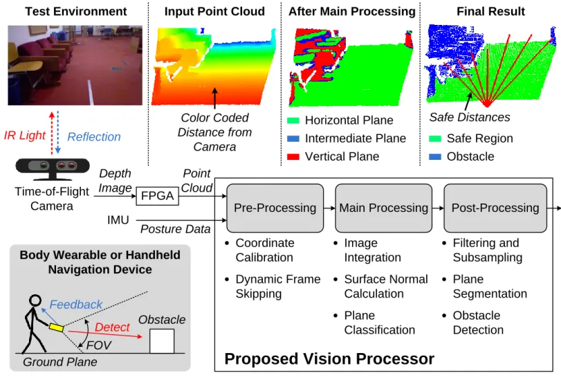
This paper describes a low-power vision processor for processing such 3D image data. The processor achieves high energy efficiency through a parallelized reconfigurable architecture and hardware-oriented algorithmic optimizations. The processor will be used as a part of a navigation device for the visually impaired (Fig.1). This handheld or body-worn device is designed to detect safe areas and obstacles and provide feedback to a user. We employ a ToF camera as the main sensor in this system since it has a small form factor and requires relatively low computational complexity [2].
The point cloud (converted in software from the raw depth image) is first reoriented based on the pitch and roll angles of the camera, as measured by an inertia measurement unit (IMU) in real time. We then apply a dynamic frame skipping algorithm, which significantly reduces power consumption by skipping processing of frames which are sufficiently similar to the previous frame. The frame-skipping algorithm divides the entire frame into multiple blocks and calculates the average depth of each block. If the number of blocks with significant depth changes does not exceed a threshold value, the processor skips all further processing of this frame and generates a frame skip signal. The frame skip signal can be used as feedback to control the frame rate of the ToF camera itself. The proposed algorithm was measured to reduce the number of frames processed by 69% in test cases of navigating through an indoor environments with variable paces.
The obstacle detection algorithm we employ is based on plane categorization. In indoor environments, artificial objects generally possess one or more perceptible planes and we utilize this property to detect obstacles. The main processing stage calculates the surface normal at each point in the cloud [3] and classifies each point as horizontal, vertical or intermediate. Post-processing filters and sub-samples this annotated cloud to reduce noise of the 3D imaging sensor. The processor then applies a plane segmentation algorithm based on region growing which groups similar neighboring points. From the extracted planes, we can differentiate the ground plane at a specific height, which is considered safe for the user to walk on, from other obstacles. The plane segmentation data can also provide information for other applications such as identifying regions of interest for object recognition. Finally, the processor calculates the distance to the closest obstacle in several different directions and sends it as a feedback so that the user can sense the environment and navigate avoiding obstacles without a cane.
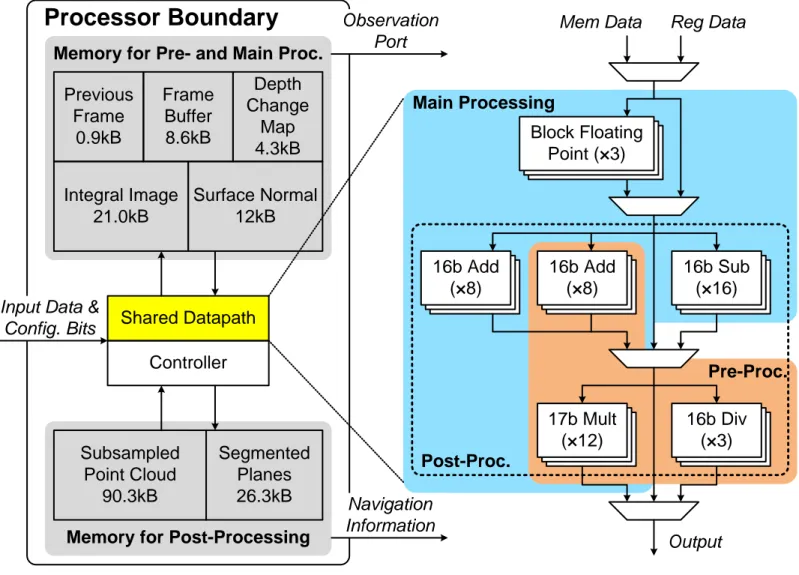
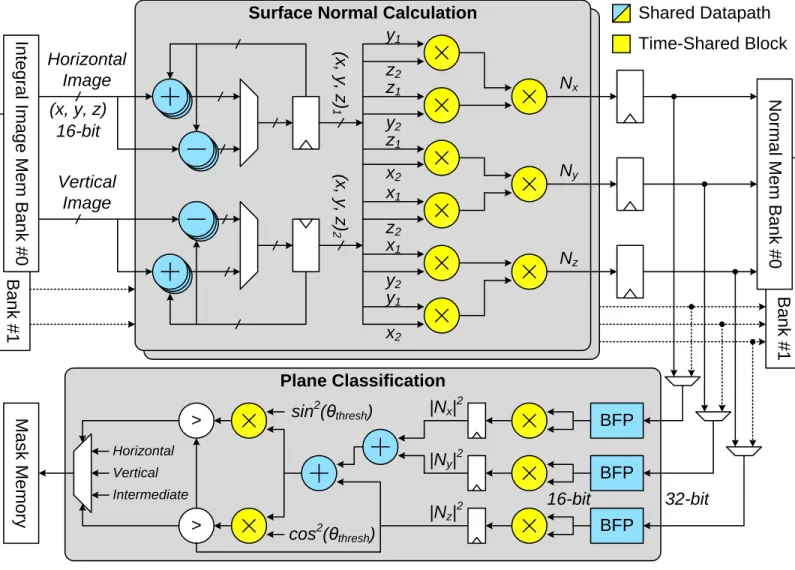
The architecture of the processor is detailed in Fig. 2. It consists of 2 memory banks totaling 163kB; one each for the first 2 processing stages and post-processing. The design has a shared datapath which is reconfigured to accommodate different parts of the processing flow with minimal hardware overheads and energy consumption. The datapath includes multiple arithmetic unit banks for parallel 16-bit ADD, SUB, MULT and DIV operations, which provide enough throughput to process input data stream in real time. In addition, the block floating point blocks take a key role in mapping long operands onto the given fixed-point datapath by dynamically changing data scale without significant accuracy degradation. These blocks observe a set of operands and move the binary point location appropriately so that 16 MSBs excluding sign extension are preserved in the largest value. Fig. 3 shows the datapath configuration for the surface normal calculation and plane classification portions of the main processing. The colored blocks are the arithmetic blocks in the datapath. Some of the blocks are not required to be active on every cycle and hence are time-shared (colored yellow).
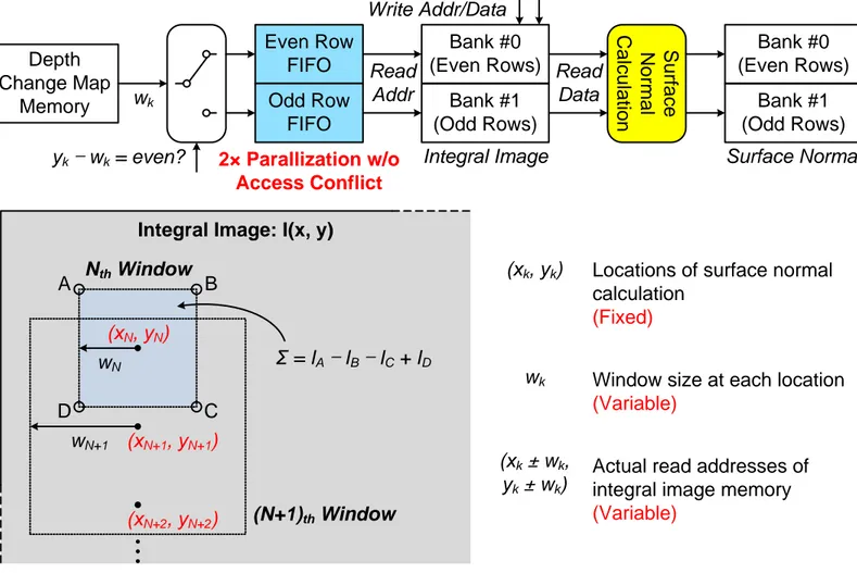
Since the surface normal calculation is one of the computation bottlenecks, we further parallelized it to process 2 locations simultaneously. However, the size of the calculation window changes based on the actual input data, making memory access patterns unpredictable and causing stalls due to memory access conflict. To address this, we implemented an out-of-order processing architecture shown in Fig. 4. The integral image block is divided into two banks storing even and odd rows. The width of the calculation window wk at each calculation point yk determines which bank the datapath needs to
access. The processor puts read addresses into one of two address FIFOs accordingly. Since each FIFO has a dedicated access to the corresponding integral image memory bank, two points can be processed at a time in out-of-order fashion unless one of the FIFOs becomes empty, which occurs infrequently when the number of even and odd memory accesses are similar on average. The proposed architecture increases throughput by 11% in simulation compared to in-order parallelization. This technique can also be directly applied to other algorithms that require extensive accesses to integral image memory such as SURF and Haar-like features [4, 5].
The annotated cloud is subsequently filtered and sub-sampled to reduce noise of the input cloud. The processor groups adjacent points that belong to the same plane type into larger planes using region growing based on [6]. The original algorithm launches search processes at arbitrary seed points and expands the current region by comparing with neighboring points in any direction. This incurs multiple comparisons especially for the points near the borders of different regions, and hence it requires excessive memory access operations and increases computation time. The arbitrary memory access pattern also impedes improving hardware efficiency further with a tailored architecture. Therefore, we developed a single pass region growing scheme depicted in Fig. 5. Instead of selecting among stored seeds, it starts at the top left point of the cloud and continues to the right pixel in the same row. Each point is only compared with the top and left points and merged to an existing region if they have similar properties such as normal vector. Note that two connected regions may not be merged until processing reaches specific location (e.g. region #1 and #5). We store the list of connected regions in a separate table so that they can ultimately be merged into a single plane. This scheme ensures that all of the points are accessed only twice throughout the search process and provides additional possibility of hardware optimization due to fixed memory access pattern, while producing exactly same results as the original algorithm. In simulation, the proposed algorithm reduces both computation time and memory accesses by 30%.
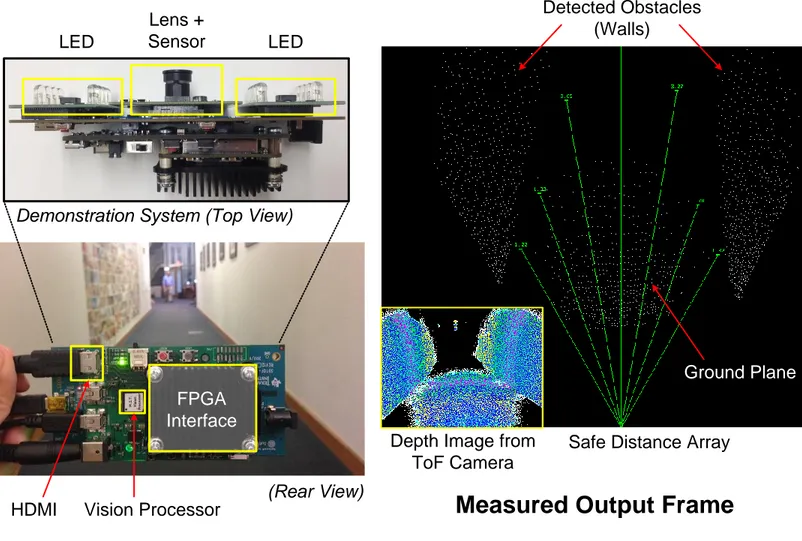
The vision processor was fabricated in 40nm CMOS process. It consumes 8mW at 0.6V, 50MHz while processing a 30fps input stream. Fig. 6 shows a prototype of the complete navigation device consisting of ToF camera, IMU, ARM processor, and the fabricated vision processor. It successfully detects obstacles and calculates safe distances in multiple directions while correcting for camera position based on the posture data from the IMU. The processor achieves more than 2 orders of magnitude better energy efficiency than a 1.7GHz quad-core ARM Cortex-A9 processor. The largest energy savings result
from the dedicated architecture, and additional savings result from the architecture optimization techniques such as out-of-order pipelining.
Acknowledgement
We thank Texas Instruments for funding and the TSMC University Shuttle Program for chip fabrication. We are also grateful to the Andrea Bocelli foundation for providing the important challenges that motivated this work. The authors thank Prof. Laura Giarré for valuable discussions.
References
[1] H. Zhang et al., “Adaptive Human-Centered Representation for Activity Recognition of Multiple Individuals from 3D Point Cloud Sequences,” IEEE Int. Conf. on Robotics and Automation, pp. 1991-1998, May 2015.
[2] J. Cho et al., “A 3-D Camera With Adaptable Background Light Suppression Using Pixel-Binning and Super-Resolution,” IEEE J. Solid-State Circuits, vol. 49, no. 10, pp. 2319-2332, Oct. 2014.
[3] S. Holzer et al., “Adaptive neighborhood selection for real-time surface normal estimation from organized point cloud data using integral images,” IEEE/RSJ Int. Conf. on Intelligent Robots and Systems, pp. 2684-2689, Oct. 2012.
[4] Y. Hanai et al., “A Versatile Recognition Processor Employing Haar-Like Feature and Cascaded Classifier,” ISSCC Dig. Tech. Papers, pp. 148-149, Feb. 2009.
[5] X. Wen et al., “Efficient Feature Selection and Classification for Vehicle Detection,” IEEE Trans. Circuits and Systems for Video Technology, vol. 25, no. 3, pp. 508-517, Mar. 2015.
[6] L. Zhu et al., “Automatic Segmentation of the Left Atrium from MR Images via Variational Region Growing With a Moments-Based Shape Prior,” IEEE Trans. Image Processing, vol. 22, no. 12, pp. 5111-5122, Dec. 2013.
Figure 1. Overview of a navigation device for the visually impaired. The device is designed as a body wearable or handheld system which can replace a conventional cane.
Test Environment
Proposed Vision Processor
Pre-Processing Coordinate Calibration Dynamic Frame Skipping Main Processing Image Integration Surface Normal Calculation Post-Processing Filtering and Subsampling Plane Segmentation Plane Classification Obstacle Detection Time-of-Flight Camera IR Light ReflectionInput Point Cloud
Color Coded Distance from
Camera
After Main Processing Final Result
Horizontal Plane Vertical Plane
Intermediate Plane Safe Region
Obstacle Safe Distances IMU Ground Plane Obstacle FOV
Body Wearable or Handheld Navigation Device Detect Feedback FPGA Point Cloud Depth Image Posture Data
Figure 2. Architecture of the processor chip, showing the shared datapath that can accommodate all required computations with minimal reconfiguration and provide high throughput through parallelization.
Navigation Information Observation
Port
Input Data & Config. Bits Previous Frame 0.9kB Integral Image 21.0kB Depth Change Map 4.3kB Surface Normal 12kB Frame Buffer 8.6kB Shared Datapath Controller Subsampled Point Cloud 90.3kB Segmented Planes 26.3kB
Processor Boundary
Memory for Pre- and Main Proc.
Memory for Post-Processing
16b Add (×8) 16b Add (×8) 16b Sub (×16) 17b Mult (×12) 16b Div (×3) Mem Data Reg Data
Main Processing Output Pre-Proc. Block Floating Point (×3) Post-Proc.
Figure 3. The shared datapath shown configured for surface normal and plane classification operations. Blue and yellow colored arithmetic blocks represent reconfigured elements of the shared datapath, where the yellow colored blocks are time-shared between two operations.
B a n k # 1 Vertical Image In te g ra l I m a g e M e m B a n k # 0 Horizontal Image (x, y, z) (x , y , z ) 1 y1 z2 (x , y , z ) 2 z1 y2 z1 x2 x1 z2 x1 y2 y1 x2 Ny Nx Nz N o rm a l M e m B a n k # 0 BFP BFP BFP 32-bit 16-bit |Nx|2 |Ny|2 |Nz|2 sin2(θthresh) cos2(θthresh) > > M a s k M e m o ry Vertical Horizontal Intermediate
Surface Normal Calculation
B a n k # 1 Plane Classification 16-bit Shared Datapath Time-Shared Block
Figure 4. The out-of-order surface normal computation scheme is shown. Since the width of processing window varies arbitrarily, read addresses of the integral image memory are selectively pushed into one of two FIFOs. The FIFOs increase throughput by 11% compared to in-order parallelization by averaging unbalanced access pattern over time.
Bank #0 (Even Rows) Bank #1 (Odd Rows) Integral Image Even Row FIFO Odd Row FIFO (xN, yN) (N+1)th Window wN wN+1 Nth Window A B C D
Integral Image: I(x, y)
Ʃ = IA – IB – IC + ID S u rfa c e N o rm a l C a lc u la tio n Bank #0 (Even Rows) Bank #1 (Odd Rows) Surface Normal Depth Change Map Memory wk (xN+1, yN+1) (xN+2, yN+2) yk – wk = even? Read Addr Write Addr/Data Read Data 2× Parallization w/o Access Conflict
Locations of surface normal calculation
(Fixed)
(xk, yk)
Window size at each location
(Variable)
wk
Actual read addresses of integral image memory
(Variable)
(xk ± wk,
Figure 5. Comparisons between conventional and proposed single-pass region growing algorithms. A fixed search pattern in the single-pass algorithm removes unnecessary pixel comparisons and hence reduces both the number of memory
accesses and the computation time by 30% in simulation.
x0 x2
p x1
x5 x3 x4
Conventional Region Growing
Region #1 (Done) Boundary Table x1 x2 x3 x4 Current Pixel
(Compare with All Neighbors)
Region #2 (Done)
Region #3 (Growing)
Next Search Points
(Arbitrary Order)
Single Pass Region Growing
Unprocessed Region Processing Order Connected Regions #1 ↔ #5 Region #2 Region #1 Region #5 Current Pixel
(Compare Only with Top and Left Pixels)
Regions Merged during Search
Figure 6. A navigation device using the fabricated processor is demonstrated. A ToF camera is on one side, and the processor and other peripherals are mounted on the other side. Measurement results show that the processor successfully detect obstacles (walls) on both sides in a long corridor and consequently generate longer safe distances toward free space in front.
FPGA Interface
Vision Processor
HDMI
Measured Output Frame
Depth Image from ToF Camera
Safe Distance Array Detected Obstacles
(Walls)
Demonstration System (Top View)
(Rear View)
LED LED
Lens + Sensor
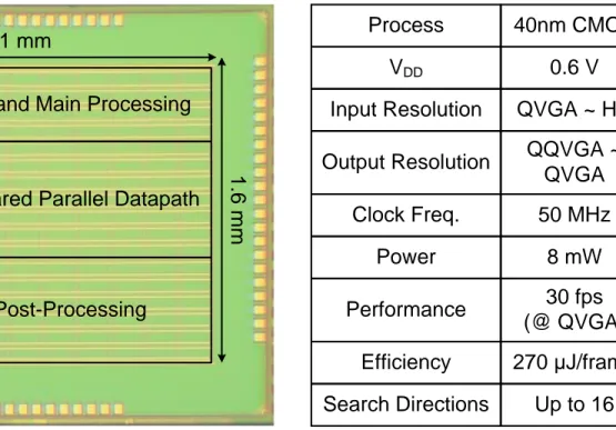
Figure 7. Die photo and a performance summary table for the processor. 2.1 mm 1 .6 m m
Memory for Pre- and Main Processing
Memory for Post-Processing Shared Parallel Datapath Controller
VDD 0.6 V
Clock Freq. 50 MHz
Process 40nm CMOS
Power 8 mW
Input Resolution QVGA ~ HD Output Resolution QQVGA ~
QVGA
Performance 30 fps (@ QVGA)
Search Directions Up to 16 Efficiency 270 μJ/frame