HAL Id: hal-01494628
https://hal.archives-ouvertes.fr/hal-01494628
Submitted on 29 Mar 2017HAL is a multi-disciplinary open access archive for the deposit and dissemination of sci-entific research documents, whether they are pub-lished or not. The documents may come from teaching and research institutions in France or abroad, or from public or private research centers.
L’archive ouverte pluridisciplinaire HAL, est destinée au dépôt et à la diffusion de documents scientifiques de niveau recherche, publiés ou non, émanant des établissements d’enseignement et de recherche français ou étrangers, des laboratoires publics ou privés.
Widely tunable directional coupler filters with 1D
photonic crystal
Bozena Jaskorzynska, Zygmunt Jacek Zawistowski, Matteo Dainese, Julien
Cardin, Lars Thylén
To cite this version:
Bozena Jaskorzynska, Zygmunt Jacek Zawistowski, Matteo Dainese, Julien Cardin, Lars Thylén. Widely tunable directional coupler filters with 1D photonic crystal. 7th International Conference Transparent Optical Networks, Jul 2005, Barcelone, Spain. �10.1109/ICTON.2005.1505769�. �hal-01494628�
Widely Tunable Directional Coupler Filters
with 1D Photonic Crystal
Bozena Jaskorzynska (1)*, Zygmunt Jacek Zawistowski (2), Matteo Dainese (1) Julien Cardin (1), Lars Thylén(1)
(1)* Royal Institute of Technology (KTH), Department of Microelectronics and Information Technology, Kista Photonics Research Center (KPRC), Electrum 229, SE - 164 40 Kista, Sweden
Tel: +46 8 790 40 62, Fax: +46 8 790 40 90, e-mail: bj@imit.kth.se
(2) Institute of Fundamental Technological Research, Polish Academy of Sciences, Department of Theory of Continuous Media, Swietokrzyska 21, 00-049 Warszawa, Poland, e-mail: zzawist@ippt.gov.pl
ABSTRACT
We present two concept examples for adding a wide range tunability to Si/SiO2 devices involving a photonic
crystal element. They are based on a directional coupler filter of two different geometries, where one of the arms is a Bragg Reflection Waveguide (BRW) used for the bandwidth improvement. The tuning relies on changing the properties of the BRW core. As an illustration we consider the smectic A* liquid crystal as the core material and show that ca 100 nm tuning range is achievable by the core index variations of 0.006 under applying electric field of 5 V/µm.
Keywords: optical filters, directional couplers, Bragg reflection waveguides, photonic crystal, liquid crystals,
electrical tuning
.
1. INTRODUCTIONDevices employing photonic crystals (PhC’s) provide unique dispersion properties that can be utilized for realizing delay lines, dispersion compensators, enhanced efficiency wavelength converters and amplifiers, or narrow bandwidth filters and lasers. Most of the reported so far PhC based components, however, are not tunable, especially those made in silicon. Adding a tuning mechanism is desired for dynamically reconfigurable WDM networks, where the wavelength allocation is changed as the needs of the network change. It is of particular interest to add a wide range dynamic tuning to PhC devices in the low-cost, but passive Si/SiO2
technology compatible with optoelectronics and the transmission fibres. This can e. g. be achieved by including micro-electro-mechanical systems (MEMS) elements, or by incorporating electro-optic materials, such as polymers or liquid crystals (LC’s). Here, as an example of a device providing a wide continuous tuning and benefiting from the dispersion properties of a PhC element for the bandwidth narrowing, we consider an extension of our earlier proposed and demonstrated [1, 2] directional coupler filter where one arm is a Bragg Reflection Waveguide (BRW), i.e. a 1D PhC waveguide. The extended concept relies in essence, on making the BRW core tunable. In the presented example we simulated tunability of the core refractive index, for which we choose the smectic A* LC’s, having the response time in the sub-microsecond regime [3], i.e. three orders of magnitude shorter than that of nematic LC’s or of the thermo-optic phase shifters. However, the concept and the conclusions are also applicable to the case when the core width is tuned, with e. g. MEMS.
We consider and compare two geometries. One being a direct extension of [2] and presented in [4], where the silicon core is replaced by LC, and a new design where one of the BRW claddings is removed and the LC forms an overlay of the coupler. The latter is much easier for practical implementation and still, as we show, preserves similar performance when properly designed.
2. FILTER GEOMETRIES AND PRINCIPAL OF OPERATION
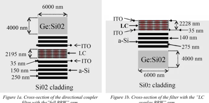
The filters we consider are both directional couplers with dissimilar arms [5]. Their cross sections are depicted in Fig. 1. One of the arms is a conventional (index guided) channel waveguide with a GeSiO2 (n2 = 1.465) core
buried in a silica glass (n1 = 1.4558). It is single mode in a wide wavelength range around 1.55 µm. The other
arm is a LC core with two (Fig. 1a), or one (Fig. 1b) Bragg Reflector claddings consisting of alternating layers of amorphous silicon (n2 = 3.55) and silica. The layer thicknesses, different for each of the cases, are given in
Fig. 1. Only transverse electric (TE) waves are considered for which the extraordinary refractive index of the LC core (smectic A* BDH764E with a 45 deg pretilt in the plane parallel to the Bragg layers – see [4]), is tuned from its off-state value n = 1.5657 by -/+0.006, which is only a half of the refractive index change possible for this liquid crystal. This corresponds to -/+ 5 V/µm variations of the electric field applied between ITO electrodes placed at both sides of the LC core. The LC core can be regarded as a defect in 1D PhC formed by the Bragg layers. The whole, vertically etched structure is buried in a silica glass cladding, however in the case (1b) there is no glass on the top.
Figure 1a. Cross-section of the directional coupler filter with the”full BRW” arm.
Figure 1b. Cross-section of the filter with the ”LC overlay BRW” arm.
The filters are designed so that when no electric field is applied (the off-state), the signal around the central wavelength of 1550 nm launched into the conventional arm, is cross-coupled to the PhC arm over the coupling length L, defined as the beating length for the two lowest supermodes of the coupler:
(
β2 β1)
π − =L , (1)
where β and 1 β are the propagation constants of the supermodes. Light at all other wavelengths stays in the 2 conventional arm. The central wavelength of the filter is determined by the phase synchronism (transverse resonance) condition [5, 6]. The filter bandwidth ∆λ-3dB is inverse proportional to the coupler length L, and to the
differential dispersion σ of the two waveguides in isolation [5]:
σ λ λ L dB 796 . 0 3 ≈ ∆ − where λ λ σ d dN d N d −
= and N , N effective indices of the respective waveguides. (2) Since the conventional GeSiO2/SiO2 arm is a low contrast waveguide of weak dispersion, to narrow the
bandwidth a given coupler length the dispersion of the other arm should be maximized. Conventional waveguides possible with low index electro-optic materials, such as polymers or liquid crystals, are also low contrast and weakly dispersive. Whereas, in PhC waveguides (including BRW’s) where light confinement at frequencies within the photonic band gap is possible for an arbitrarily low index core [7], high dispersion can be achieved by the PhC cladding design. By applying the BRW waveguide as one of the coupler arm we obtained a fourfold bandwidth-length product improvement without an extensive effort on the optimization. The main issue for the further analysis is determination of the tuning range.
3. PERFORMANCE ANALYSIS AND RESULTS
For approximate analysis of the tuning properties we used 1D formalism of Ref. 8, based on the scattering matrix method for stratified media, combined with the effective index method to account for the lateral confinement. In order to determine the tuning range we have analyzed the performance of the filter with respect to the following criteria:
The cross-coupling to the same mode should occur over the whole tuning range.
The difference between the propagation constants of the supermodes, determining the coupling length (1), should not vary too much with wavelength since it results in extinction-ratio variation.
Relative dispersion slopes for the two supermodes should not exhibit strong variation either, so that the filter bandwidth variation is kept within acceptable limits.
For directional couplers there is a well known [6] trade off between the bandwidth ∆λ-3dB and the intrinsic tuning
rate dλ dn: dn dN A dn d σ σ λ = 1 = 1 , (3) since both scale inverse proportional with the differential dispersion. There is some room though for their
(
)
N dn N n n N N n A ∂ ∂ − + = φ π λ λ 2 , , 2 2 . (4)Where d is the BRW core width, and φ is the phase shift under reflection from the Bragg cladding, which can be influenced by the choice of the layer thickness and when applicable, also the layer material. Since N lies in the range of the total internal reflection at the glass/Si interfaces the phase shift strongly depends on N, especially when it is chosen so that the incidence angles are close to the critical one. The simultaneous optimization can also be achieved by increasing the coupler length.
Having the above guidelines in mind we have made a preliminary optimization, where we compromised the bandwidth-length product in favor of the tuning range and its quality. In Fig. 2 we show an example of the tuning rate dependence on the Si layer thickness, for the coupler with a LC overlay (Fig. 1b). The curves are shown for several values of the silica layer thickness. The circle shows the chosen pair of the thicknesses for the Bragg cladding, which allowed increase of the tuning rate at the least degradation of the bandwidth, and of the filter performance over the total tuning range.
Figure 2. Dependence of the tuning rate on a Si layer thickness b, for different thicknesses of the silica layer. The circle indicates the choice made for the „overlay” case of Fig. 1b.
The latter is illustrated in Fig. 3, where the dispersion curves of the coupler are shown at the off-state and the extremes of the tuning range for both of the considered filters. For coupler 1a, the variations of the coupling length (1) over the range 1510 nm – 1589 nm, do not exceed 19%, hence the resulting variations of the amplitude are below 3%. The bandwidth (2) variations from its off-set value of 1.2 nm (at 7.4 mm length) are below 6% over the whole tuning range. For the filter with a LC overlay (Fig. 1b) a slightly better performance was obtained, probably because we have put more effort on its optimization.
Figure 3a. Supermode dispersion at the off-state (1550 nm) and the extremes of the tuning range for
±∆n0.006 (±∆E5 µ/Vm) for filter (1a).
Figure 3b. Supermode dispersion at the off-state (1550 nm) and the extremes of the tuning range for
±∆n0.006 (±∆E5 µ/Vm) for filter (1b).
The variations of the coupling length from its off-state value of 8.95 mm, and the resulting amplitude variations are in that case below 11% and 1.5%, respectively. Larger tuning range: 1503 nm – 1597 nm was obtained for the same value -/+ 5 V/µm of the applied field. Although the slope of the dispersion varies a bit more, the resulting bandwidth variations from its off-state value of 1.05 nm are still kept below 11%. Both of the filters are
designed for coupling between the fundamental (0-order) mode in the conventional arm and the first-order mode in the BRW arm. We have checked that the cross-coupling to the higher modes does not occur in a much wider wavelength range than the tuning ranges we show here.
4. SUMMARY
We analysed two design ideas for widely tunable filters based on directional couplers in which one arm is a conventional waveguide and the other is a BRW with a core formed by a commercially available smectic A* liquid crystal. We have checked that by applying BRW instead of a conventional waveguide with a LC core and silica cladding, a fourfold bandwidth narrowing is readily achievable for the same coupler lengths. We showed that tuning ranges of ca 90 nm around the 1.55 µm wavelength under applying the electric field of less than 5 V/µm, are feasible for both of the considered filters. Both of them show similar performance. Although for the filter with an overlay the bandwidth-length product is slightly worse, 1.05 nm x 8.95 mm to compare with 1.2 nm x 7.4 mm obtained for the full BRW case, it has better stability to the tuning variations, larger tunabilty range, and is easier to fabricate. We sketched the optimization guidelines and made a preliminary optimization in which the compromise was made between the bandwidth-length product and the tuning rate, with a focus on obtaining a wide tunability range. The presented designs and guidelines are readily applicable for other tuning mechanisms, e.g. where the BRW core width is tuned with MEMS.
ACKNOWLEDGEMENTS
This work is included in COST P11 action and the European Network of Excellence PHOREMOST. The support from the Swedish Research Council (VR), the Swedish Foundation for Strategic Research (SSF), and the (Polish) State Committee for Scientific Research (KBN), is gratefully acknowledged.
REFERENCES
[1] M. Dainese, M. Swillo, L. Thylen, M. Qiu, L. Wosinski, B. Jaskorzynska, and V. Shushunova, „Narrow band coupler based on one-dimensional Bragg reflection waveguide”, in Proc. OFC 2003, Atlanta, USA, March 2003, paper MF39.
[2] Valeriya Shushunova, Marcin Swillo, Bozena Jaskorzynska, Min Qiu and Lars Thylén, „Separation of Optical Modes in a Coupler on the Basis of the Bragg One-Dimensional Grating”, J. Appl. Spectroscopy vol. 70, pp. 298-302 (2003).
[3] Anat Sneh, Hristina m. Johnson, Jian-Yu Liu, „High_Speed Wavelength Tunable Liquid Crystal Filter”,
IEEE Photonics Technol. Lett. 7, pp. 379-381 (1995).
[4] Zygmunt Jacek Zawistowski, Bozena Jaskorzynska, „Electrically tunable filter based on directional coupler with 1D photonic crystal arm infiltrated with smectic liquid crystal”, Proc. of 6th Int. Conf. on Transparent
Optical Networks and European Symposium on Photonic Crystals, (ICTON/ESPC), Wroclaw, July 2004,
vol. 2, pp. 127-130.
[5] D. Marcuse, „Bandwith of forward and backward coupling directional couplers", J. Lightwave Techn., 5, pp. 1773-1777 (1987).
[6] R.C. Alferness and R.V. Schmidt „Tunable optical waveguide directional coupler filter”, Appl. Phys. Lett.
33, pp. 161 – 163 (1978).
[7] P.Yeh, A.Yariv, C.S. Hong, „Electromagnetic propagation in periodic stratified media”, J. Opt. Soc. Am.,
67, pp 423-448 (1977).
[8] T.D. Visser, H. Blok, D. Lenstra, „Modal analysis of a planar waveguide with Gain and Losses”,