HAL Id: cea-01840742
https://hal-cea.archives-ouvertes.fr/cea-01840742
Submitted on 16 Jul 2018HAL is a multi-disciplinary open access archive for the deposit and dissemination of sci-entific research documents, whether they are pub-lished or not. The documents may come from teaching and research institutions in France or abroad, or from public or private research centers.
L’archive ouverte pluridisciplinaire HAL, est destinée au dépôt et à la diffusion de documents scientifiques de niveau recherche, publiés ou non, émanant des établissements d’enseignement et de recherche français ou étrangers, des laboratoires publics ou privés.
All Optical Fiber Sensor based on Optically Stimulated
Luminescence for radiation detection
Olivier Roy, Sylvain Magne, J.-C. Gaucher, L. Albert, L. Dusseau, J.C
Bessières, Pierre Ferdinand
To cite this version:
Olivier Roy, Sylvain Magne, J.-C. Gaucher, L. Albert, L. Dusseau, et al.. All Optical Fiber Sensor based on Optically Stimulated Luminescence for radiation detection. 12th Conference on Optical Fiber Sensor (OFS12), OSA Technical Digest Series, Optical Society of America, 1997, Williamsburg, United States. pp.666-669. �cea-01840742�
666 / PDP4- 1
All Optical Fiber Sensor based on
Optically Stimulated Luminescence
for radiation detection
0. Roy’, S. Magne’, J.C. Gaucher’, L. Albert*, L. Dusseau*, J.C. Bessi&e3 and P. Ferdinand’
“‘LETI (CEA - Technologies Avades)
DEJN - SPE - Optical Measurement Laboratory CE/Saclay 91191 Gif-sur-Yvette Ccdex France
Tel. : 33 (0)1.69.08.83.39 Fax : 33 (0)1.69.08.83.95 E-mail : [email protected]
%niver& Montpellier II
Place Eugene Bataillon, CEM2 - CC 083 34095 Montpellier CedexO5 France
Tel. : 33 (0)4 67 14 38 25 Fax : 33 (0)4 67 14 38 10 E-mail : [email protected] (3) CORAD
Pam industriel et technologiclue de la Pompignene,
Rue de la vieille postc - BrEt. T4 - 34 055 Montpcllier Cedex 1 France Tel. : 33 (0)4 67 34 49 93 Fax : 33 (0)4 67 34 44 45 E-mail : atrad(@ibm.net
Key words : Optical Fiber Sensor (OFS), Optically Stimulated Luminescence (OSL), Radiation Detection, Luminescent Materials.
I. Introduction and Background
In nuclear industry, radiation protection is one of the most important matter of concern. By now, dosimetry is achieved with photographic films (the legal dosimeters in France), ThermoLuminescent Dosimeters (TLD) and electronic ones. All of them measure local dose. In the tie of the ALARA concept (As Low As Reasonably Achievable), we develop in our laboratory, specialist in optical sensors, a new approach based on optical fiber and luminescent materials presenting the phenomenon of Optically Stimulated Luminescence (OSL) (closely related phenomenon to lhermoLuminescence [l]) in order to improve the remote dosimetry monitoring. So, as TLD, OSL material can trap electrons, created by several hind of irradiation (UV, X, ‘y,...), on stable levels. But instead of being realised thermally electrons are released by light and produce a luminescence which is proportional to the ((data stored )) left by irradiation enabling the dose measurement. The OSL phenomenon offers the same advantages as TLD and the interesting possibility of a remote optical stimulation. On this assumption, we have developed a radiation sensor based on an Optically Stirnulable Luminescent (OSL) material [2,3] coupled with an optical fiber. Rare earth doped Alkaline Earth Sulfides (ARS) were selected as phosphor materials due to their relatively low Z,,T (14.5 for Magnesium sulfide).
II. OSL phenomenon
The OSL phenomenon derives from the simultaneous presence in the material’s forbidden band of both trap levels and luminescent centers. When irradiated by W, X or y rays, OSL materials collect a fraction of the radiation induced charges, electrons or holes, on trap energy levels distributed in wide gap materials. As OSL is closely related to Thermohuninenco, OSL materials are generally thermoluminescent. Nevertheless the reverse assumption is not necessary true. In the former TL case, the trapped charges are released by heating the material, whereas in the later they are released by optically stimulating the OSL material in a convenient wavelength band (fig. 1). Then, the released carriers recombine with huninescence center emitting a specific optical spectrum. It has been shown that the amount of this luminescence is proportional to the deposited dose [4].
Reprinted with permission from the 12th International Conference on Optical Fiber Sensors, 1997 OSA Technical Digest Series, Vol. 16, Optical Society of America (Washington, D.C., 1997). c 1997 OSA.
PDP4-2 I 667 ..
0. ROY et al. (( All Optical Fiber Sensor based on Optically Stimulated Luminescence for radiation detection D, 12* International Conference on Optical Fiber Sensors OFS’97, Oct. 28-3 1, 1997, Williamsburg, Virginia, USA
Trap level
emitted light
irradiation
opticalstimulation
Luminescent
centre
Figure 1 : OSL phenomenon, after [5]
From the end-user point of view, OSL is very interesting because it conveys advantages of TL (long data storage time, good reproducibility, large dynamic range, low level dose detection, . ..) with an optical stimulation instead of a thermal one [6].
III. Phosphor material used in the OFS
Phosphor materials are widely used, particularly for dosimetry purposes based on ThermoLuminescence (TL) and now on Optically Stimulated Luminescence (OSL) techniques. In our applicative context, we have selected Alkaline Earth Sulfides doped with rare earth ions @ES), more particularly MgS provided by CORAD (Montpellier - France) due to their low Z,E and possibility of photon energy compensation for personal dosimetv. After irradiation (IN, X, y, e-) this kind of material could easily be stimulated by infrared light to retrieve the dose information through the emitted light with an optical fiber in the visible region. In our << all Optical Fiber Sensor D), 1 mg of OSL crystalline transducer is connected at the end of an optical fiber. The size of the transducer is adjusted to match the 200 p core diameter of the multimode fiber used (fig. 2).
Figure 2 : The OSL transducer connected at the fiber end
N. Optical Fiber prototype
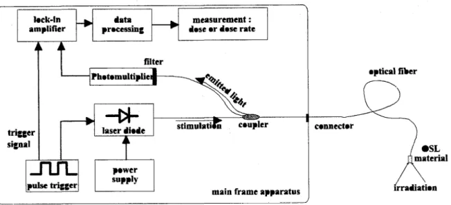
Our laboratory has developed a specific handable demonstrator to test OSL phosphors and able to be used on sites (fig. 3). After an irradiation by “‘Cs (2.65 pGy/min) or @ ‘Co (10 mGy/min) source either a X-rays source (50 kev), the phosphor material is stimulated by IR light emitted by a diode laser. The luminescence is detected by a module using a mini-photomultiplier R6800 (Hamamatsu) coupled with a BG 42 filter (Schott glass) which removes the IR stimulation and lets pass the emitted light. The stimulation is obtained by a pigtailed laser diode which wavelength is 862 mn with a power density Isti, (862 mn) = 56 W/cmz. All experiments were done at room temperature.
668 I PDP4-3 trigger signal optical fiber cmnecter l SL
x
material irradiation Figure 3 Optical Fiber Sensor principle based on OSL material for dosimetryThis prototype is able to measure both dose and dose rate. By a fast interrogation rate it can provide a real-time measurement very useful for workers under radiation fields or for remote dosimetry. It can also multiplex several sensors. In case of electronic failure, the remote mainframe apparatus can be repaired or changed without any information loss since the transducing material keeps on integrating the dose.
V. Experiments and results
The phosphor material was irradiated at increasing doses, then stimulated with the infrared light emitted by the laser diode. The induced luminescence was detected in order to explore the signal WYSUS dose linearity of the Optical Fiber Sensor. Figure 4 presents a typical OSL signal obtained with this prototype. The OSL follows an inverse power law decay like l/t’ with a within 1 and 2 [7]. For very strong doses, the time of zeroing increases rapidly. 300 250 A 5 ai 200 .g 150 2 2 3 100 50 0 - OSL Signal -noise floor 0 600 800 1000 1200 1400 1600 1800 2000 Time (ms)
PDP4-4 / 669
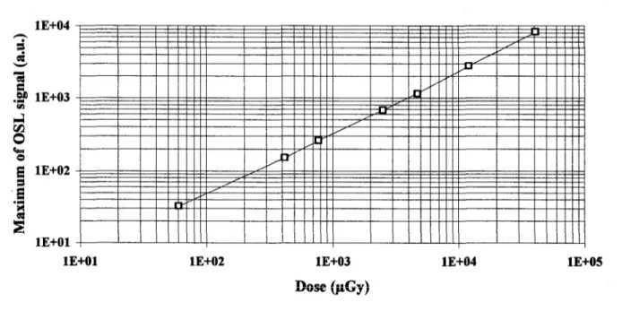
These experiments yielded a 40 pGy lowest measurable dose and showed no saturation up to more than 10 Gy tfig. 5). lE+04 h i d E lE+02 .z ‘B E lE+Ol , I I I
lE+Ol lE+O2 lE+O3 lE+O4 lE+O5
Dose WY)
Figure 5 : Maximum of OSL signal versus dose VI. Conclusion
Rare earth doped AES are interesting candidates for dosimetry purposes. Conveying the advantages of thermoluminescence, (long time data storage, good reproducibility, large dynamic range, low level dose detection,
. . .) they can be stimulated with a laser beam through an optical fiber which allows to quickly erase the signal given access to real time measurement. The fading and quick zeroing are still to be studied extensively further in order to achieve a usable system devoted to a real industrial context.
This new kind of Optical Fiber Sensor can certainly improve the management of radiation protection for workers or nuclear plants by its real-time display of dose or dose rate. Moreover, OSL phenomenon is not only of great interest for dosimetry but also for other research fields like medical imaging or optical memory.
Ackuowledgments
We would like to thank Pr. J. Gasiot, and Pr. J. Fesquet from the University Moutpellier II, France, as well as Pr R. Visocekas from the University Denis Diderot (paris 7), France, for fruitful discussions.
References
[l] S.W.S. McKeever, ‘Thermoluminescence of Solids’, Cambridge Solid State Science Series, University Press, Cambridge, 1988
[2] J.H. Schuhnan, ‘Survey of luminescence’ 1” Int. Conf on Luminescence Dosimetry, Stanford, 1965, p 3
[3] J. Gasiot et al., ‘Nanosecond infrared laser stimulation of luminescence rare-earth doped AES’, Appl. Phys. L&t., Vol. 40, 1982, p. 376
[4] 0. Missous et al., ‘Optically stimulated lmninescence of rare-earth doped phosphors’, European. J. Solid state inorg. Chem. Vol. 28,1991, p. 163
[5] RP. Johnson, ‘Luminescence of sulfide and silicate phosphors’, J. Opt. Sot. Am., Vol. 29, 1939, p. 387
[6] 0. Roy et al, ‘Dosimkie par fibre optique’, Jomn&zs sur 1’Instrumentation de Radioprotection des Travaillems, Saclay (1995), in French
[7] 0. Roy et al, ‘Time Decay of the Optically Stimulated Luminescence in MgS doped with rare earths’, 6* Int. conf. on Luminescent Material, Paris, 1997
![Figure 1 : OSL phenomenon, after [5]](https://thumb-eu.123doks.com/thumbv2/123doknet/12927015.373783/3.918.104.774.152.497/figure-osl-phenomenon-after.webp)