Cost-Effectiveness Comparison of Coupler Designs of Wireless
Power Transfer for Electric Vehicle Dynamic Charging
The MIT Faculty has made this article openly available.
Please share
how this access benefits you. Your story matters.
Citation
Chen, Weitong, Chunhua Liu, Christopher Lee, and Zhiqiang Shan.
“Cost-Effectiveness Comparison of Coupler Designs of Wireless
Power Transfer for Electric Vehicle Dynamic Charging.” Energies 9,
no. 11 (November 2, 2016): 906.
As Published
http://dx.doi.org/10.3390/en9110906
Publisher
MDPI AG
Version
Final published version
Citable link
http://hdl.handle.net/1721.1/107012
Terms of Use
Creative Commons Attribution 4.0 International License
energies
Article
Cost-Effectiveness Comparison of Coupler Designs
of Wireless Power Transfer for Electric Vehicle
Dynamic Charging
Weitong Chen1, Chunhua Liu1,*, Christopher H.T. Lee2and Zhiqiang Shan1
1 School of Energy and Environment, City University of Hong Kong, 83 Tat Chee Avenue, Kowloon Tong, Hong Kong, China; weitong.chen@outlook.com (W.C.); zhiqishan2-c@my.cityu.hk (Z.S.)
2 Research Laboratory of Electronics, Massachusetts Institute of Technology, Cambridge, MA 02139, USA; chtlee@mit.edu
* Correspondence: chualiu@eee.hku.hk; Tel.: +852-3442-2885 Academic Editor: Hongjian Sun
Received: 9 July 2016; Accepted: 26 October 2016; Published: 2 November 2016
Abstract:This paper presents a cost-effectiveness comparison of coupler designs for wireless power transfer (WPT), meant for electric vehicle (EV) dynamic charging. The design comparison of three common types of couplers is first based on the raw material cost, output power, transfer efficiency, tolerance of horizontal offset, and flux density. Then, the optimal cost-effectiveness combination is selected for EV dynamic charging. The corresponding performances of the proposed charging system are compared and analyzed by both simulation and experimentation. The results verify the validity of the proposed dynamic charging system for EVs.
Keywords: cost-effectiveness; dynamic charging; electric vehicle; electromagnetic field analysis; wireless power transfer
1. Introduction
Wireless power transfer (WPT) has attracted more and more attention for contactless charging and has been developed significantly for various applications in recent years [1–3], such as cell phone charging [4], grid fault detection [5], biomedical implants [6], etc. WPT technologies have been demonstrated to be suitable for complex operating situations [7,8]. As the study of electric vehicles (EV) has received increasing attention due to environmental considerations, the WPT technique has offered a new strategy for improving the driving experience of EVs. One of the important concerns about EVs is battery drawbacks, such as the capacity, size, weight, and charging time, which greatly limits the driving distance of EVs [9,10]. To solve this problem, a dynamic charging system adopting WPT has been proposed to extend the driving distance of EVs [11–13].
However, economic issues should be considered because of the high initial investment when a dynamic charging system via WPT is implemented. Previous research works have investigated different shapes of coil couplers for WPT [14–18]. But these works have not discussed the trade-off between the cost and the performance of the dynamic WPT charging system for EVs.
The purpose of this paper is to investigate the cost-effectiveness and the performance of three types of coil couplers with different shapes, including rectangular, circular, and hexagonal. Based on the same volume of raw materials, their corresponding WPT performances will be quantitatively compared and analyzed. In this way, the optimal type will be confirmed to design the coil topology for the EV dynamic charging with better characteristics and less investment. Both simulation and experimentation will be carried out to prove the validity of the proposed dynamic charging system with optimal cost-effectiveness.
The rest of the paper is organized as follow. Section2will discuss and compare the common three types of coupler designs based on cost-effectiveness and performance. Section3will present the proposed dynamic charging system for EVs with optimal cost-effectiveness. Then, in Section4, conclusions will be drawn.
2. Cost-Effectiveness Comparison of Basic Coupler Designs
2.1. Basic Topology and Coupler Design
Various circuit topologies of the WPT systems have been discussed and proposed on the basis of different preferences for the system utilities [1–4]. The series–series topology is selected in the proposed dynamic charging system since it has been proved to be suitable for long track applications by previous research [18,19]. Figure1shows the basic series–series topology of the WPT system.
The rest of the paper is organized as follow. Section 2 will discuss and compare the common three types of coupler designs based on cost-effectiveness and performance. Section 3 will present the proposed dynamic charging system for EVs with optimal cost-effectiveness. Then, in Section 4, conclusions will be drawn.
2. Cost-Effectiveness Comparison of Basic Coupler Designs
2.1. Basic Topology and Coupler Design
Various circuit topologies of the WPT systems have been discussed and proposed on the basis of different preferences for the system utilities [1–4]. The series–series topology is selected in the proposed dynamic charging system since it has been proved to be suitable for long track applications by previous research [18,19]. Figure 1 shows the basic series–series topology of the WPT system.
Figure 1. Basic series–series topology of WPT system.
The abovementioned WPT system mainly consists of the transmitting and receiving circuits, and the power is transferred by a couple of coils (L1 and L2). C1 and C2 are the compensation
capacitors to compensate the inductance thus the system can operate at the designed frequency. RLoad
represents the load of the system, where a simplified resistor can basically represent the rectifier, driving system, charging system, etc. in EV dynamic WPT applications. R1 and R2 are the internal
resistance of the transmitting and receiving circuit, respectively. The mutual inductance M between the coils determines the quantity of the transferred power. A large M value is normally expected which can provide large power output [19,20], since the output power can be expressed as:
2 1 2 M P wI Q L (1)
where ω is the angular frequency, I1 is the current in the transmitting circuit, and Q is the quality
factor of the receiving circuit. Thus, the mutual inductance M can be determined as:
1 2
M k L L (2)
where k is the coupling coefficient of the coupler. According to the equations, the coupling coefficient, which is affected by the shape of the coils, distance and angle between the coils, etc., has a square relation with the output power. This means that the change of the coupler shapes will result in the change of the coupling coefficient, and further affect the output power significantly.
Figure 2 demonstrates three shapes of couplers for the cost-effectiveness comparison, which includes the rectangular type, the circular type, and the hexagonal type. The dimension design of three couplers is based on practical considerations: the effective area and the amount of material usage. The size of coil is limited by the width of a given road. Hence, the side length of rectangular coils, the diameter of circular coils and the diagonal length of hexagonal coils are designed to be equal. In order to perform the cost-effectiveness comparison, the volume of each kind of coupler is designed to be the same. Thus, the turn number of different shape couplers is different. It should be
Figure 1.Basic series–series topology of WPT system.
The abovementioned WPT system mainly consists of the transmitting and receiving circuits, and the power is transferred by a couple of coils (L1and L2). C1and C2are the compensation capacitors to compensate the inductance thus the system can operate at the designed frequency. RLoadrepresents the load of the system, where a simplified resistor can basically represent the rectifier, driving system, charging system, etc. in EV dynamic WPT applications. R1and R2are the internal resistance of the transmitting and receiving circuit, respectively. The mutual inductance M between the coils determines the quantity of the transferred power. A large M value is normally expected which can provide large power output [19,20], since the output power can be expressed as:
P= M
2 L2
wI1Q (1)
where w is the angular frequency, I1is the current in the transmitting circuit, and Q is the quality factor of the receiving circuit. Thus, the mutual inductance M can be determined as:
M=kpL1L2 (2)
where k is the coupling coefficient of the coupler. According to the equations, the coupling coefficient, which is affected by the shape of the coils, distance and angle between the coils, etc., has a square relation with the output power. This means that the change of the coupler shapes will result in the change of the coupling coefficient, and further affect the output power significantly.
Figure 2 demonstrates three shapes of couplers for the cost-effectiveness comparison, which includes the rectangular type, the circular type, and the hexagonal type. The dimension design of three couplers is based on practical considerations: the effective area and the amount of material usage. The size of coil is limited by the width of a given road. Hence, the side length of rectangular coils, the diameter of circular coils and the diagonal length of hexagonal coils are designed to be equal.
Energies 2016, 9, 906 3 of 13
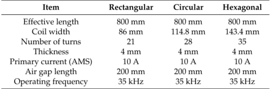
In order to perform the cost-effectiveness comparison, the volume of each kind of coupler is designed to be the same. Thus, the turn number of different shape couplers is different. It should be noted that the coreless type couplers are normally adopted since the core loss will affect the accuracy [21]. The design specifications are shown in Table1.
Energies 2016, 9, 906 3 of 13
noted that the coreless type couplers are normally adopted since the core loss will affect the accuracy [21]. The design specifications are shown in Table 1.
(a)
(b)
(c)
Figure 2. Three types of couplers for comparison. (a) Rectangular coils; (b) Circular coils; (c)
Hexagonal coils. Width 86 mm Air gap 200 mm Length 800mm Width 114.8 mm Air gap 200 mm Diameter 800mm Air gap 200 mm Width 143.4 mm Diagonal length 800 mm
Figure 2. Three types of couplers for comparison. (a) Rectangular coils; (b) Circular coils; (c) Hexagonal coils.
Table 1.Design specification of different couplers.
Item Rectangular Circular Hexagonal
Effective length 800 mm 800 mm 800 mm
Coil width 86 mm 114.8 mm 143.4 mm
Number of turns 21 28 35
Thickness 4 mm 4 mm 4 mm
Primary current (AMS) 10 A 10 A 10 A
Air gap length 200 mm 200 mm 200 mm
Operating frequency 35 kHz 35 kHz 35 kHz
2.2. Comparison and Analysis
By using the finite element method (FEM) with the JMAG Designer tool, the performances and characteristics of the three types of couplers are calculated and compared. Figure3shows the magnetic flux distributions of the three types of couplers. As can be seen in Figure3, these couplers are all highly activated. However, the extents of excitation of each are different due to the shapes. Thus, the magnetic fields and the power outputs of them should be also different.
Figure4illustrates the output power of the three types of couplers in the condition of various horizontal offsets under the load of 18 ohm. It can be seen in the figure that the output power of the three types of coils decreases when the horizontal alignment changes from 0 mm to 400 mm. Although the hexagonal coil shows the maximum output power at the central position, its output power becomes the weakest one when the horizontal misalignment reaches 400 mm. Notably, in this procedure, the rectangular coil shows the greater tolerance of horizontal misalignment among the three type of coils. Thus, it means that these three types of coils possess different natures for practical considerations and applications.
Table 1. Design specification of different couplers.
Item Rectangular Circular Hexagonal
Effective length 800 mm 800 mm 800 mm Coil width 86 mm 114.8 mm 143.4 mm Number of turns 21 28 35
Thickness 4 mm 4 mm 4 mm Primary current (AMS) 10 A 10 A 10 A
Air gap length 200 mm 200 mm 200 mm Operating frequency 35 kHz 35 kHz 35 kHz
2.2. Comparison and Analysis
By using the finite element method (FEM) with the JMAG Designer tool, the performances and characteristics of the three types of couplers are calculated and compared. Figure 3 shows the magnetic flux distributions of the three types of couplers. As can be seen in Figure 3, these couplers are all highly activated. However, the extents of excitation of each are different due to the shapes. Thus, the magnetic fields and the power outputs of them should be also different.
Figure 4 illustrates the output power of the three types of couplers in the condition of various horizontal offsets under the load of 18 ohm. It can be seen in the figure that the output power of the three types of coils decreases when the horizontal alignment changes from 0 mm to 400 mm. Although the hexagonal coil shows the maximum output power at the central position, its output power becomes the weakest one when the horizontal misalignment reaches 400 mm. Notably, in this procedure, the rectangular coil shows the greater tolerance of horizontal misalignment among the three type of coils. Thus, it means that these three types of coils possess different natures for practical considerations and applications.
(a) Receiving coil
Transmitting coil
Magnetic Flux Density Contour Plot: T 8.5×10⁻³ 6.6×10⁻³ 4.7×10⁻³ 2.8×10⁻³ 9.4×10⁻⁴ 0 Figure 3. Cont.
Energies 2016, 9, 906 5 of 13
Energies 2016, 9, 906 5 of 13
(b)
(c)
Figure 3. Contour graphs of magnetic flux distributions. (a) Rectangular couplers; (b) Circular couplers; (c) Hexagonal couplers.
Receiving coil
Transmitting coil
Magnetic Flux Density Contour Plot: T 8.5×10⁻³ 6.6×10⁻³ 4.7×10⁻³ 2.8×10⁻³ 9.4×10⁻⁴ 0
Receiving coil
Transmitting coil
Magnetic Flux Density Contour Plot: T 8.5×10⁻³ 6.6×10⁻³ 4.7×10⁻³ 2.8×10⁻³ 9.4×10⁻⁴ 0
Figure 3.Contour graphs of magnetic flux distributions. (a) Rectangular couplers; (b) Circular couplers; (c) Hexagonal couplers.
Figure 4. Output power under horizontal offsets. (a) Diagram of horizontal offset; (b) Comparison of output power.
In engineering applications, a WPT system for EV charging should be implemented by considering maximum power output capability for the effective charging area under the minimum material cost. Thus, an evaluation equation is created for wireless power charging of EVs by this paper which can effectively and quantitatively estimate the cost-effectiveness of a WPT system via the power output, the effective area, and the material volume, as follows.
P S CE
V
(3)
where P stands for the output power, S stands for the effective area, and V stands for material use by volume. As P and S are the numerators of the equation, the CE value increases when the output power and the effective charging area are increment. On the other hand, as V is the denominator of the equation, the CE value increases when the material volume of coils become less. Thus, by taking into account the output power, the effective area for power transmission, and the copper usage per volume, the cost-effectiveness for the WPT coupler can be evaluated and compared quantitatively. Namely, the larger CE value represents the better cost-effectiveness of the coupler type. It should be noted that the CE evaluation index is based on the coupler shapes of the transmission coil and the receiving coil and independently on the time. Also, if the region is given, such as a road, the larger
CE indicates the better coupler design.
For the optimally fixed position (x = 0), the values of the cost-effectiveness for the rectangular, circular, and hexagonal couplers are 2736 kW/m, 2952 kW/m and 3229 kW/m, respectively. However, in the procedure of dynamic charging which can be regarded as the periodic horizontal offsets, the average value of the cost-effectiveness should be considered. The values of the average cost-effectiveness for the rectangular, circular and hexagonal couplers are 1675 kW/m, 1615 kW/m, and 1653 kW/m, respectively.
Therefore, by analyzing the values of the cost-effectiveness for the static (aligned position) and dynamic (horizontal misalignment positions) charging circumstances, the corresponding conclusions can be drawn:
• The rectangular coil can be used as the main transmitting part for dynamic charging since it has the larger cost-effectiveness value. Namely, the rectangular coil has the better capability of transferring the power under the suitable material cost.
• The hexagonal coil can be used as the main transmitting part for the static charging since it has the larger cost-effectiveness value. On the other hand, the hexagonal coil can be used as the auxiliary part for the dynamic charging because it has the ability of concentrating the output power at a specific point.
X Z Transmission Coil Receiving Coil Horizontal Offset (a) (b)
Figure 4.Output power under horizontal offsets. (a) Diagram of horizontal offset; (b) Comparison of output power.
In engineering applications, a WPT system for EV charging should be implemented by considering maximum power output capability for the effective charging area under the minimum material cost. Thus, an evaluation equation is created for wireless power charging of EVs by this paper which can effectively and quantitatively estimate the cost-effectiveness of a WPT system via the power output, the effective area, and the material volume, as follows.
CE= P·S
V (3)
where P stands for the output power, S stands for the effective area, and V stands for material use by volume. As P and S are the numerators of the equation, the CE value increases when the output power and the effective charging area are increment. On the other hand, as V is the denominator of the equation, the CE value increases when the material volume of coils become less. Thus, by taking into account the output power, the effective area for power transmission, and the copper usage per volume, the cost-effectiveness for the WPT coupler can be evaluated and compared quantitatively. Namely, the larger CE value represents the better cost-effectiveness of the coupler type. It should be noted that the CE evaluation index is based on the coupler shapes of the transmission coil and the receiving coil and independently on the time. Also, if the region is given, such as a road, the larger CE indicates the better coupler design.
For the optimally fixed position (x = 0), the values of the cost-effectiveness for the rectangular, circular, and hexagonal couplers are 2736 kW/m, 2952 kW/m and 3229 kW/m, respectively. However, in the procedure of dynamic charging which can be regarded as the periodic horizontal offsets, the average value of the cost-effectiveness should be considered. The values of the average cost-effectiveness for the rectangular, circular and hexagonal couplers are 1675 kW/m, 1615 kW/m, and 1653 kW/m, respectively.
Therefore, by analyzing the values of the cost-effectiveness for the static (aligned position) and dynamic (horizontal misalignment positions) charging circumstances, the corresponding conclusions can be drawn:
• The rectangular coil can be used as the main transmitting part for dynamic charging since it has the larger cost-effectiveness value. Namely, the rectangular coil has the better capability of transferring the power under the suitable material cost.
• The hexagonal coil can be used as the main transmitting part for the static charging since it has the larger cost-effectiveness value. On the other hand, the hexagonal coil can be used as the auxiliary part for the dynamic charging because it has the ability of concentrating the output power at a specific point.
Energies 2016, 9, 906 7 of 13
• The circular coil has the medium value of the cost-effectiveness for the power transfer. Hence, this type of coupler is not preferred for the system installation.
• The CE equation includes the power output and the effective area, which directly relate with the charging frequency and the charging distance. When the frequency is higher, the power would be higher for the same WPT system. Also, when the distance is larger, the power would be less for the same WPT system. Actually, the CE equation is for the general cost-effectiveness estimation of a WPT system, which is independent from the charging frequency and the charging distance.
3. Proposed Dynamic Charging System
3.1. System Configuration
In order to transfer the power to the receiving coil, EV dynamic charging systems normally adopt a long-track primary coil for transmitting the power [12,21–23]. Figure5shows the schematic of the EV dynamic charging system, which consists of the power source, the transmitting coils, the receiving coil, the driving and charging system, and the auxiliary devices. In this way, the EV dynamic charging system allows the EV to pick up the continuous electrical energy from the power source during driving.
Energies 2016, 9, 906 7 of 13
• The circular coil has the medium value of the cost-effectiveness for the power transfer. Hence, this type of coupler is not preferred for the system installation.
• The CE equation includes the power output and the effective area, which directly relate with the charging frequency and the charging distance. When the frequency is higher, the power would be higher for the same WPT system. Also, when the distance is larger, the power would be less for the same WPT system. Actually, the CE equation is for the general cost-effectiveness estimation of a WPT system, which is independent from the charging frequency and the charging distance.
3. Proposed Dynamic Charging System
3.1. System Configuration
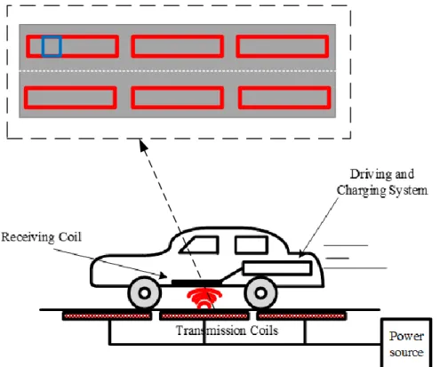
In order to transfer the power to the receiving coil, EV dynamic charging systems normally adopt a long-track primary coil for transmitting the power [12,21–23]. Figure 5 shows the schematic of the EV dynamic charging system, which consists of the power source, the transmitting coils, the receiving coil, the driving and charging system, and the auxiliary devices. In this way, the EV dynamic charging system allows the EV to pick up the continuous electrical energy from the power source during driving.
Figure 5. Schematic of EV dynamic charging system.
Specifically, the transmission coils are beneath the road and connect with the power source. Under the resonant frequency, the receiving coil which is installed at the bottom of the car can pick up the continuous energy from the transmitting coils through the dynamic driving procedure. Based on the above conclusion of the cost-effectiveness for static and dynamic charging, the transmitter combines the rectangular with hexagonal coils together rather than the conventional long-track rectangular coil.
Figure 6 shows the design of a conventional long-track coil and Figure 7 illustrates the proposed combined-type transmitting coil. The criteria of transmitting coil design are based on the same volume of material usage, and the same effective length and area.
Figure 5.Schematic of EV dynamic charging system.
Specifically, the transmission coils are beneath the road and connect with the power source. Under the resonant frequency, the receiving coil which is installed at the bottom of the car can pick up the continuous energy from the transmitting coils through the dynamic driving procedure. Based on the above conclusion of the cost-effectiveness for static and dynamic charging, the transmitter combines the rectangular with hexagonal coils together rather than the conventional long-track rectangular coil.
Figure6shows the design of a conventional long-track coil and Figure7illustrates the proposed combined-type transmitting coil. The criteria of transmitting coil design are based on the same volume of material usage, and the same effective length and area.
Energies 2016, 9, 906 8 of 13 The receiving coil adopts the rectangular design as shown in Table 1, which is due to the vehicle shape. The design specifications of transmitting coils are given in Table 2. The combined type of transmitting coil does not cover the edge and corner of the road. Thus, the material is used less than the conventional coils. Hence, if the two types of transmitting coils use the same volume of materials, the number of turns of the proposed combined type coil is bigger than that of the conventional coil. Furthermore, the electromagnetic field will be concentrated to the body of the road rather than distributed to edges and corners. Also, this design fits the track of vehicles which normally run on the road. Therefore, the output power can be increased significantly along the central line of the road by the proposed combined type.
Figure 6. Conventional transmitting coil for dynamic charging. (a) Transmitting and receiving coils; (b) Transmitting coil.
Figure 7. Proposed combined type transmitting coil for dynamic charging. (a) Transmitting and receiving coils; (b) Transmitting coil.
Table 2. Design specifications of transmitting coils for EV dynamic charging. Item Conventional Type Combined Type
Total length 2400 mm 2400 mm
Coil width 86 mm 98.3 mm
Number of turns 21 24
Thickness 4 mm 4 mm
Primary current (AMS) 10 A 10 A
Air gap length 200 mm 200 mm
Operating frequency 35 kHz 35 kHz
3.2. Simulation Result
Figure 8 shows the output power of the dynamic charging system while the receiving coil is moving along the transmitting coil at optimal positions under the load of 18 ohm. As can be seen in the figure, the output power of the combined-type coil is significantly higher than that of the conventional coil from 400 mm to 2000 mm. Also, the power of the combined type is only slightly smaller than the conventional one before 400 mm and after 2000 mm, in which is at the edge of the transmitting coil. This illustrates that the proposed combined-type coil has the better performance for power transmission for EV dynamic charging.
Coil length 2400 mm Width 86 mm (a) (b) Coil length 2400 mm Square section length 1707.2 mm
Width 98.3 mm
(a) (b)
Figure 6.Conventional transmitting coil for dynamic charging. (a) Transmitting and receiving coils; (b) Transmitting coil.
The receiving coil adopts the rectangular design as shown in Table 1, which is due to the vehicle shape. The design specifications of transmitting coils are given in Table 2. The combined type of transmitting coil does not cover the edge and corner of the road. Thus, the material is used less than the conventional coils. Hence, if the two types of transmitting coils use the same volume of materials, the number of turns of the proposed combined type coil is bigger than that of the conventional coil. Furthermore, the electromagnetic field will be concentrated to the body of the road rather than distributed to edges and corners. Also, this design fits the track of vehicles which normally run on the road. Therefore, the output power can be increased significantly along the central line of the road by the proposed combined type.
Figure 6. Conventional transmitting coil for dynamic charging. (a) Transmitting and receiving coils; (b) Transmitting coil.
Figure 7. Proposed combined type transmitting coil for dynamic charging. (a) Transmitting and receiving coils; (b) Transmitting coil.
Table 2. Design specifications of transmitting coils for EV dynamic charging. Item Conventional Type Combined Type
Total length 2400 mm 2400 mm
Coil width 86 mm 98.3 mm
Number of turns 21 24
Thickness 4 mm 4 mm
Primary current (AMS) 10 A 10 A
Air gap length 200 mm 200 mm
Operating frequency 35 kHz 35 kHz
3.2. Simulation Result
Figure 8 shows the output power of the dynamic charging system while the receiving coil is moving along the transmitting coil at optimal positions under the load of 18 ohm. As can be seen in the figure, the output power of the combined-type coil is significantly higher than that of the conventional coil from 400 mm to 2000 mm. Also, the power of the combined type is only slightly smaller than the conventional one before 400 mm and after 2000 mm, in which is at the edge of the transmitting coil. This illustrates that the proposed combined-type coil has the better performance for power transmission for EV dynamic charging.
Coil length 2400 mm Width 86 mm (a) (b) Coil length 2400 mm Square section length 1707.2 mm
Width 98.3 mm
(a) (b)
Figure 7. Proposed combined type transmitting coil for dynamic charging. (a) Transmitting and receiving coils; (b) Transmitting coil.
The receiving coil adopts the rectangular design as shown in Table1, which is due to the vehicle shape. The design specifications of transmitting coils are given in Table2. The combined type of transmitting coil does not cover the edge and corner of the road. Thus, the material is used less than the conventional coils. Hence, if the two types of transmitting coils use the same volume of materials, the number of turns of the proposed combined type coil is bigger than that of the conventional coil. Furthermore, the electromagnetic field will be concentrated to the body of the road rather than distributed to edges and corners. Also, this design fits the track of vehicles which normally run on the road. Therefore, the output power can be increased significantly along the central line of the road by the proposed combined type.
Table 2.Design specifications of transmitting coils for EV dynamic charging. Item Conventional Type Combined Type
Total length 2400 mm 2400 mm
Coil width 86 mm 98.3 mm
Number of turns 21 24
Thickness 4 mm 4 mm
Primary current (AMS) 10 A 10 A
Air gap length 200 mm 200 mm
Operating frequency 35 kHz 35 kHz
3.2. Simulation Result
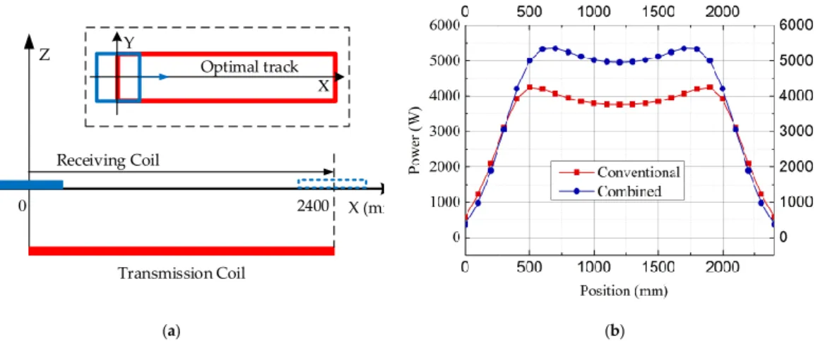
Figure8shows the output power of the dynamic charging system while the receiving coil is moving along the transmitting coil at optimal positions under the load of 18 ohm. As can be seen in the figure, the output power of the combined-type coil is significantly higher than that of the conventional coil from 400 mm to 2000 mm. Also, the power of the combined type is only slightly smaller than the conventional one before 400 mm and after 2000 mm, in which is at the edge of the transmitting coil. This illustrates that the proposed combined-type coil has the better performance for power transmission for EV dynamic charging.
Energies 2016, 9, 906Energies 2016, 9, 906 9 of 139 of 13
Figure 8. Dynamic charging performance. (a) Diagram of dynamic charging procedure; (b) Output power comparison of conventional-type and combined-type coils.
The magnetic flux distribution of the transmitting coil is calculated by FEM and demonstrated in Figure 9 under a load of 18 ohm. As shown in the graph, the magnetic flux density of combined-type transmitting coil is higher and more concentrated to the center. In practical situation, the vehicle drivers are able to control their vehicles to run within this range, and most drivers prefer to drive along the center of the roads rather than edge of the roads. Although the convention coil has slightly greater tolerance of misalignment at the corner of the coil, most of the magnetic flux distributed at the corner is out of use due to the driver habit. Thus, the proposed combined-type coil can improve the output power in practical circumstances.
(a)
(b)
Figure 9. Magnetic flux distribution. (a) Conventional-type coil; (b) Combined-type coil. X (mm) Z Transmission Coil Receiving Coil 0 2400 Optimal track Y X (a) (b)
Figure 8.Dynamic charging performance. (a) Diagram of dynamic charging procedure; (b) Output power comparison of conventional-type and combined-type coils.
The magnetic flux distribution of the transmitting coil is calculated by FEM and demonstrated in Figure9under a load of 18 ohm. As shown in the graph, the magnetic flux density of combined-type transmitting coil is higher and more concentrated to the center. In practical situation, the vehicle drivers are able to control their vehicles to run within this range, and most drivers prefer to drive along the center of the roads rather than edge of the roads. Although the convention coil has slightly greater tolerance of misalignment at the corner of the coil, most of the magnetic flux distributed at the corner is out of use due to the driver habit. Thus, the proposed combined-type coil can improve the output power in practical circumstances.
Energies 2016, 9, 906 9 of 13
Figure 8. Dynamic charging performance. (a) Diagram of dynamic charging procedure; (b) Output power comparison of conventional-type and combined-type coils.
The magnetic flux distribution of the transmitting coil is calculated by FEM and demonstrated in Figure 9 under a load of 18 ohm. As shown in the graph, the magnetic flux density of combined-type transmitting coil is higher and more concentrated to the center. In practical situation, the vehicle drivers are able to control their vehicles to run within this range, and most drivers prefer to drive along the center of the roads rather than edge of the roads. Although the convention coil has slightly greater tolerance of misalignment at the corner of the coil, most of the magnetic flux distributed at the corner is out of use due to the driver habit. Thus, the proposed combined-type coil can improve the output power in practical circumstances.
(a)
(b)
Figure 9. Magnetic flux distribution. (a) Conventional-type coil; (b) Combined-type coil. X (mm) Z Transmission Coil Receiving Coil 0 2400 Optimal track Y X (a) (b)
3.3. Experimentation Result
In order to compare and verify the conventional-type and combined-type coils for EV dynamic charging, experimentation was performed. Figure10shows the testing system, which consists of the signal function generator, power amplifier, testing models, oscilloscope, and auxiliary devices. For experimentation, the prototype of the charging system is designed with proportions of 10:1. The specifications of the conventional-type transmitting coil, the combined-type transmitting coil, and the receiving coil are listed in Table3.
Energies 2016, 9, 906 10 of 13
3.3. Experimentation Result
In order to compare and verify the conventional-type and combined-type coils for EV dynamic charging, experimentation was performed. Figure 10 shows the testing system, which consists of the signal function generator, power amplifier, testing models, oscilloscope, and auxiliary devices. For experimentation, the prototype of the charging system is designed with proportions of 10:1. The specifications of the conventional-type transmitting coil, the combined-type transmitting coil, and the receiving coil are listed in Table 3.
Figure 10. Testing bed of experimentation. Table 3. Specifications of coils for experimentation.
Item Conventional
Transmitting Coil
Combined
Transmitting Coil Receiving Coil
Coil length 240 mm 240 mm 80 mm Coil width 25.5 mm 30.4 mm 25.5 mm Number of turns 21 25 21 Thickness 1.2 mm 1.2 mm 1.2 mm Inductance 0.0967 mH 0.1022 mH 0.02784 mH Capacitance 220 nF 204 nF 746 nF
Resistance 0.4059 ohm 0.407 ohm 0.1435 ohm
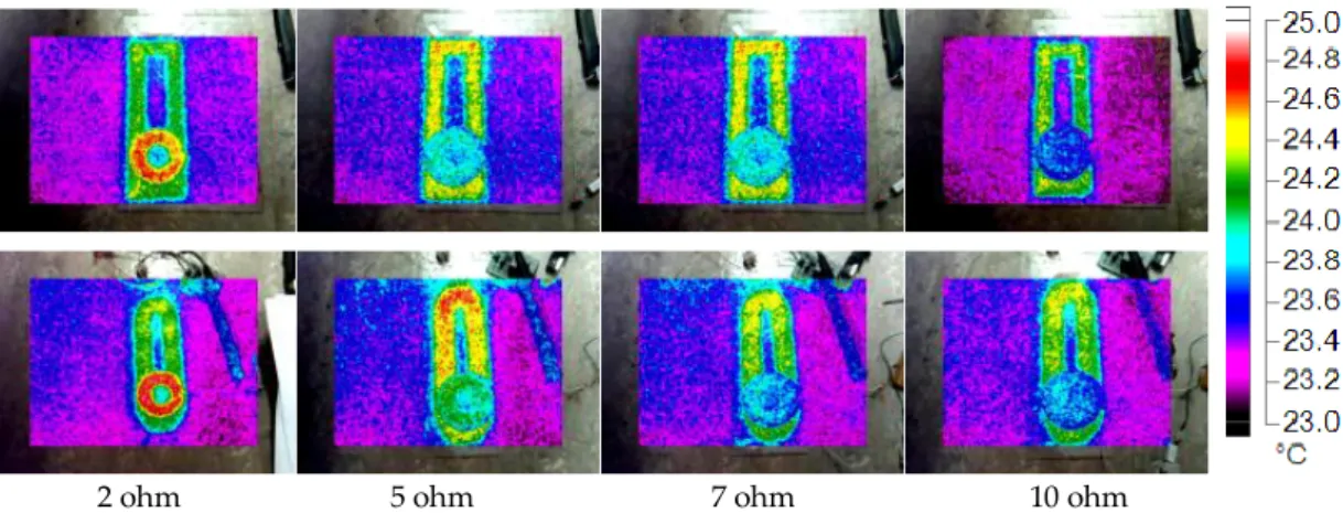
Figure 11 shows the thermal images of conventional type and combined type of systems when the receiving coil was connecting to loads under different resistances. In Figure 11, it can be found that the temperature of the system is decreased when the resistance of loads is increased. And the combined type of the first row has the slightly higher temperature than that of the conventional type of the second row at the same load resistance. It indicates that the proposed combined type of WPT system can produce much more power under the same input current.
Oscilloscope
Amplifier
Models
Signal
generator
Figure 10.Testing bed of experimentation. Table 3.Specifications of coils for experimentation.
Item Conventional Transmitting Coil Combined Transmitting Coil Receiving Coil
Coil length 240 mm 240 mm 80 mm Coil width 25.5 mm 30.4 mm 25.5 mm Number of turns 21 25 21 Thickness 1.2 mm 1.2 mm 1.2 mm Inductance 0.0967 mH 0.1022 mH 0.02784 mH Capacitance 220 nF 204 nF 746 nF
Resistance 0.4059 ohm 0.407 ohm 0.1435 ohm
Figure11shows the thermal images of conventional type and combined type of systems when the receiving coil was connecting to loads under different resistances. In Figure11, it can be found that the temperature of the system is decreased when the resistance of loads is increased. And the combined type of the first row has the slightly higher temperature than that of the conventional type of the second row at the same load resistance. It indicates that the proposed combined type of WPT system can produce much more power under the same input current.
Then, the VA rate is evaluated for both conventional type and combined type, when the receiving coil moves along the optimal track of the transmitting coil. Figure12a–c present the VA rate of the transmitting circuit under load resistances of 5 ohm, 7 ohm and 10 ohm, respectively. It should be noted that the VA rate is not the efficiency of the active power since the existence of inevitable reactive power in practical circuits. However, the VA rate can truly reflect the differences in actual efficiencies of the system. As can be seen in the figures, the VA rates of both systems increase significantly when the receiving coil moves from 0 cm to 3 cm. Also, the efficiency of the systems decreases when the resistance of the load increases from 5 ohm to 10 ohm. It is obvious that the efficiency of the combined topology is higher than that of the conventional topology in most circumstances. In fact, the performances of both systems when the receiving coil approaches the edge of transmitting coil become worse.
Energies 2016, 9, 906 11 of 13
Energies 2016, 9, 906 11 of 13
Figure 11. Thermal images of conventional-type and combined-type of WPT systems under different
loads.
Then, the VA rate is evaluated for both conventional type and combined type, when the receiving coil moves along the optimal track of the transmitting coil. Figure 12a–c present the VA rate of the transmitting circuit under load resistances of 5 ohm, 7 ohm and 10 ohm, respectively. It should be noted that the VA rate is not the efficiency of the active power since the existence of inevitable reactive power in practical circuits. However, the VA rate can truly reflect the differences in actual efficiencies of the system. As can be seen in the figures, the VA rates of both systems increase significantly when the receiving coil moves from 0 cm to 3 cm. Also, the efficiency of the systems decreases when the resistance of the load increases from 5 ohm to 10 ohm. It is obvious that the efficiency of the combined topology is higher than that of the conventional topology in most circumstances. In fact, the performances of both systems when the receiving coil approaches the edge of transmitting coil become worse.
(a) (b)
(c)
2 ohm 5 ohm 7 ohm 10 ohm
(a) (b) (c) (a) (b) (c) (a) (b) (c)
Figure 11. Thermal images of conventional-type and combined-type of WPT systems under different loads.
Energies 2016, 9, 906 11 of 13
Figure 11. Thermal images of conventional-type and combined-type of WPT systems under different
loads.
Then, the VA rate is evaluated for both conventional type and combined type, when the receiving coil moves along the optimal track of the transmitting coil. Figure 12a–c present the VA rate of the transmitting circuit under load resistances of 5 ohm, 7 ohm and 10 ohm, respectively. It should be noted that the VA rate is not the efficiency of the active power since the existence of inevitable reactive power in practical circuits. However, the VA rate can truly reflect the differences in actual efficiencies of the system. As can be seen in the figures, the VA rates of both systems increase significantly when the receiving coil moves from 0 cm to 3 cm. Also, the efficiency of the systems decreases when the resistance of the load increases from 5 ohm to 10 ohm. It is obvious that the efficiency of the combined topology is higher than that of the conventional topology in most circumstances. In fact, the performances of both systems when the receiving coil approaches the edge of transmitting coil become worse.
(a) (b)
(c)
2 ohm 5 ohm 7 ohm 10 ohm
(a) (b) (c) (a) (b) (c) (a) (b) (c)
Figure 12. Measured VA rate of the transmitting circuit under different loads. (a) Load of 5 ohm; (b) Load of 7 ohm; (c) Load 10 of ohm.
4. Conclusions
In this paper, a cost-effectiveness comparison of coupler designs is firstly carried out for EV dynamic charging. The corresponding CE equation is created according to the output power, the effective area, and the copper material volume. Then, based on the optimal cost-effectiveness suggestion for coupler design, a new combined-type coil is proposed and compared with the conventional-type coil for the WPT system. Both simulation and experimentation are accomplished, which illustrate that the combined-type of WPT system is more cost-effective than the conventional type. The corresponding performances are given and discussed to verify the validity of the proposed design.
Acknowledgments: This work described in this paper was partially supported by a grant from the Research Grants Council of the Hong Kong Special Administrative Region, China (Project No. CityU 21201216). Also, it was supported in part by a grant from City University of Hong Kong, HKSAR, China (Project No. 7200486 (SEE)). Author Contributions: The work presented in this paper is the output of research projects undertaken by Chunhua Liu. Chunhua Liu developed the topic, revised, review, and supervised the whole paper. Weitong Chen performed the calculation, experimentation and paper writing. Christopher H.T. Lee and Zhiqiang Shan reviewed and improved the paper.
Conflicts of Interest:The authors declare no conflict of interest. References
1. Hui, S.Y.R.; Zhong, W.; Lee, C.K. A Critical Review of Recent Progress in Mid-Range Wireless Power Transfer. IEEE Trans. Power Electron. 2014, 29, 4500–4511. [CrossRef]
2. Lee, C.K.; Zhong, W.X.; Hui, S.Y.R. Effects of magnetic coupling of nonadjacent resonators on wireless power domino-resonator systems. IEEE Trans. Power Electron. 2012, 27, 1905–1916. [CrossRef]
3. Zhang, J.; Cheng, C. Analysis and optimization of three-resonator wireless power transfer system for predetermined-goals wireless power transmission. Energies 2016, 9, 274. [CrossRef]
4. Jang, Y.; Jovanovi´c, M.M. A contactless electrical energy transmission system for portable-telephone battery chargers. IEEE Trans. Ind. Electron. 2003, 50, 520–527. [CrossRef]
5. Liu, C.; Chau, K.T.; Zhang, Z.; Qiu, C.; Li, W.; Ching, T.W. Wireless power transfer and fault diagnosis of high-voltage power line via robotic bird. J. Appl. Phys. 2015, 117, 17D521. [CrossRef]
6. Ramrakhyani, A.K.; Mirabbasi, S.; Mu Chiao, M.C. Design and optimization of resonance-based efficient wireless power delivery systems for biomedical implants. IEEE Trans. Biomed. Circuits Syst. 2011, 5, 48–63. [CrossRef] [PubMed]
7. Liu, C.; Chau, K.T.; Qiu, C.; Lin, F. Investigation of energy harvesting for magnetic sensor arrays on Mars by wireless power transmission. J. Appl. Phys. 2014, 115, 2014–2017. [CrossRef]
8. Liu, C.; Chau, K.T.; Zhang, Z.; Qiu, C.; Lin, F.; Ching, T.W. Multiple-receptor wireless power transfer for magnetic sensors charging on Mars via magnetic resonant coupling. J. Appl. Phys. 2015, 117, 17A743. [CrossRef]
9. Chan, C.C. The state of the art of electric, hybrid, and fuel cell vehicles. IEEE Proc. 2007, 95, 704–718. [CrossRef]
10. Burke, A. Batteries and Ultracapacitors for Electric, Hybrid, and Fuel Cell Vehicles. IEEE Proc. 2007, 95, 806–820. [CrossRef]
11. Suh, N.P.; Cho, D.H.; Rim, C.T. Design of on-line electric vehicle (OLEV). In Global Product Development, Proceedings of the 20th CIRP Design Conference, Nantes, France, 19–21 April 2010; pp. 3–8.
12. Lee, S.; Huh, J.; Park, C.; Choi, N.-S.; Cho, G.-H.; Rim, C.-T. On-Line electric vehicle using inductive power transfer system. In Proceedings of the 2010 IEEE Energy Conversion Congress and Exposition (ECCE), Atlanta, GA, USA, 12–16 September 2010; pp. 1598–1601.
13. Wang, Z.; Wei, X.; Dai, H. Design and Control of a 3 kW Wireless Power Transfer System for Electric Vehicles. Energies 2015, 9, 10. [CrossRef]
14. Qiu, C.; Chau, K.T.; Liu, C.; Li, W.; Lin, F. Quantitative comparison of dynamic flux distribution of magnetic couplers for roadway electric vehicle wireless charging system. J. Appl. Phys. 2014, 115, 17A334. [CrossRef] 15. Nian, X. Pad Design for a Move-and-Charge System for Electric Vehicles. In Proceedings of the 2014 Makassar International Conference on Electrical Engineering and Informatics, Makassar, Indonesia, 26–30 November 2014; pp. 97–102.
16. Hui, S.Y.R.; Ho, W.W.C. A new generation of universal contactless battery charging platform for portable consumer electronic equipment. IEEE Trans. Power Electron. 2005, 20, 620–627. [CrossRef]
17. Budhia, M.; Boys, J.T.; Covic, G.A.; Huang, C.Y. Development of a single-sided flux magnetic coupler for electric vehicle IPT charging systems. IEEE Trans. Ind. Electron. 2013, 60, 318–328. [CrossRef]
18. Wang, C.-S.; Stielau, O.H.; Covic, G.A. Design Considerations for a Contactless Electric Vehicle Battery Charger. IEEE Trans. Ind. Electron. 2005, 52, 1308–1314. [CrossRef]
19. Shin, J.; Shin, S.; Kim, Y.; Ahn, S.; Lee, S.; Jung, G.; Jeon, S.-J.; Cho, D.H. Design and Implementation of Shaped Magnetic Resonance Based Wireless Power Transfer System for Roadway-Powered Moving Electric Vehicles. IEEE Trans. Ind. Electron. 2014, 61, 1179–1192. [CrossRef]
Energies 2016, 9, 906 13 of 13
20. Zhang, Z.; Chau, K.T.; Liu, C.; Li, F.; Ching, T.W. Quantitative Analysis of Mutual Inductance for Optimal Wireless Power Transfer via Magnetic Resonant Coupling. IEEE Trans. Magn. 2014, 50, 1–4. [CrossRef] 21. Thai, V.X.; Choi, S.Y.; Choi, B.H.; Kim, J.H.; Rim, C.T. Coreless Power Supply Rails Compatible with both
Stationary and Dynamic Charging of Electric Vehicles. In Proceedings of the 2015 IEEE 2nd International Future Energy Electronics Conference (IFEEC), Kaohsiung, Taiwan, 1–4 November 2015.
22. Yilmaz, M.; Buyukdegirmenci, V.T.; Krein, P.T. General design requirements and analysis of roadbed inductive power transfer system for dynamic electric vehicle charging. In Proceedings of the 2012 IEEE Transportation Electrification Conference and Expo (ITEC), Dearborn, MI, USA, 18–20 June 2012; pp. 1–6. 23. Throngnumchai, K.; Hanamura, A.; Naruse, Y.; Takeda, K. Design and Evaluation of a Wireless Power
Transfer System with Road Embedded Transmitter Coils for Dynamic Charging of Electric Vehicles. In Proceedings of the 2013 World Electric Vehicle Symposium and Exhibition (EVS27), Barcelona, Spain, 17–20 November 2013; pp. 1–10.
© 2016 by the authors; licensee MDPI, Basel, Switzerland. This article is an open access article distributed under the terms and conditions of the Creative Commons Attribution (CC-BY) license (http://creativecommons.org/licenses/by/4.0/).