Design, Testing, and Validation of the Search for
Extra-Terrestrial Genomes Instrument
by
Srinivasa Aditya Bhattaru
B.S. Mechanical Engineering California Institute of Technology, 2015
Submitted to the Department of Aeronautics and Astronautics in partial fulfillment of the requirements for the degree of
Master of Science in Aeronautics and Astronautics at the
MASSACHUSETTS INSTITUTE OF TECHNOLOGY June 2018
0
Massachusetts Institute of Technology 2018. All rights reserved.ASignature
redacted,
Author-..
Certified by....
Depatmerl of Aeronautics and Astronautics
Sray
2 4 2 0 18Signature redacted
---.
Professor
Jeffrey A. Hoffman of th ractice of Aeronautics and Astronautics Thesis Supervisor
A ccepted by ...
MASSACUTS ILNSTITUTOF TECHNOLOGY
JUN 28 2018
LIBRARIES
Signature redacted
Hamsa Balakrishnan Associate Professor of Aeronautics and Astronautics Chair, Graduate Program Committee
Design, Testing, and Validation of the Search for
Extra-Terrestrial Genomes Instrument
by
Srinivasa Aditya Bhattaru
Submitted to the Department of Aeronautics and Astronautics on May 24, 2018, in partial fulfillment of the
requirements for the degree of
Master of Science in Aeronautics and Astronautics
Abstract
The development of any spaceflight instrument involves a systematic, iterative process of design, testing, and validation. This ensures that the system developed will meet the needs of stakeholders while minimizing costs and risks. Here, the needs for a life-detection instrument targeting nucleic acids are identified, the objectives for that instrument are determined, and system engineering analysis is used to demonstrate that a Search for Extra-Terrestrial Genomes instrument would fulfill those objectives and is feasible for a rover mission. Additionally, we show our design and build process for a testbed to rapidly prototype SETG components and subsystems, which has successfully automated nucleic acid extraction, sequencer loading, and parts of library preparation. We also experiment with thermal simulations and conduct a sequencing test at Martian conditions, using a custom built thermal vacuum chamber system. Finally, this thesis explores potential avenues for future development and identifies short term and long term engineering goals that would assist the SETG team in developing an instrument prototype.
Thesis Supervisor: Jeffrey A. Hoffman
Acknowledgments
I am grateful for all of my mentors in the SETG project, including Prof. Jeff Hoffman, Dr. Christopher Carr, and Dr. Jacopo Tani, for patiently guiding me to become a better researcher and a better writer.
Additionally, I am also thankful for the entire SETG team with their incredible research and stellar support: my thesis is built on their shoulders.
The entire department at Aeronautics and Astronautics is filled with people who have provided me with the support and structure with which I could conduct this research, and for that they have my gratitude.
A special thank you goes to my family and friends, who believed in me no matter my successes or setbacks. I couldn't have written this without you.
Finally, I am of course very grateful to the NASA MatISSE program as well as the National Science Foundation Graduate Research Fellowship Program for their funding, allowing me to work on a truly one-of-a-kind project and forge my path to the future.
Contents
1 Introduction
1.1 The Search for Extraterrestrial Life 1.1.1 Motivation . . . . 1.2 Biosignatures . . . . 1.2.1 Properties of Life . . . . 1.2.2 Biomarkers . . . .
1.3 DNA Detection for the Discovery of Extent Life . . 1.3.1
1.3.2 1.3.3
Panspermia . . . . Informational Polymers . .
Search for Extraterrestrial Genomes (SETG) 2 Systems Engineering of SETG
2.1 Needs . . . .. .. . 2.2 Objectives . . . . 2.3 Requirements . . . . 2.3.1 Technical Requirements 2.4 Subsystems . . . . 2.4.1 Inlet . . . . 2.4.2 Sample Preparation. 2.4.3 Library Preparation 2.4.4 Sequencing . . . . 2.4.5 Data Processing . . . . 2.4.6 Waste Management . . 15 15 15 16 16 17 17 17 18 19 21 . . . . 21 . . . . 21 . . . . 22 . . . . 23 . . . . 24 . . . . 24 . . . . 25 . . . . 26 . . . . 27 . . . . 29 . . . . 29 . . . . . . . . . . . .
2.4.7 Power Conditioning and Thermal Control . . . . 30
2.4.8 Structure . . . . 31
2.5 M ass, Volume, and Energy Budgets . . . . 31
2.6 Discussion . . . . 32
3 TRL5 Development 33 3.1 SETG Automation . . . . 33
3.1.1 Overview . . . . 33
3.1.2 Current Best Solution . . . . 34
3.2 Components and M ethods . . . . 36
3.2.1 W ork-flow . . . . 36 3.2.2 Hardware . . . . 38 3.2.3 Software . . . . 39 3.3 Design . . . . 39 3.3.1 Extraction . . . . 40 3.3.2 Library Preparation . . . . 41 3.3.3 Sequencing . . . . 43 3.3.4 Additional Subsystems . . . . 43
3.4 Testing and Results . . . . 45
3.4.1 Extraction . . . . 45 3.4.2 Library Preparation . . . . 48 3.4.3 Sequencing . . . . 50 3.4.4 Additional Subsystems . . . . 51 3.5 Future W ork . . . . 53 3.5.1 Advantages . . . . 53 3.5.2 Limitations . . . . 54 3.5.3 Challenges . . . . 54 3.6 Continued Development . . . . 55 3.6.1 Preparing for TRL6 . . . . 56
4 Towards an Integrated SETG 57
4.1 Lessons Learned from TRL4 and TRL5 . . . . 57
4.2 Preliminary Steps . . . . 58
4.2.1 Thermal Vacuum . . . . 58
4.2.2 Testing and Validating . . . . 59
4.3 Sequencing in Martian Conditions . . . . 62
4.3.1 Hardware Setup . . . . 62
4.3.2 Sequencing Experiment . . . . 63
4.4 Simulation . . . . 64
4.5 Continued Work . . . . 66
5 Analysis and Conclusions 67 5.1 Technology Readiness Level of Instrument . . . . 67
5.2 Future Work . . . . 67
5.2.1 Challenges and Knowledge Gaps . . . . 68
5.3 Potential Solutions . . . . 69
5.3.1 Simulations and Models . . . . 69
5.3.2 Future Tests . . . . 70
5.4 Conclusion . . . . 70
List of Figures
2-1 Prototype Sample Preparation Cartridge . . . . 26 2-2 Diagram of Library Preparation Protocol for Ligation, adapted from
Oxford Nanopore Technologies . . . . 28 3-1 Automated SETG Testbed Block Diagram. Power and Waste
Man-agement are shown as additional subsystems. Structure and Data Pro-cessing are not, and are less relevant at this stage of testing. ... 34 3-2 Automated SETG Testbed Flowchart. Each numbered box is a
reser-voir within the system . . . . 40 3-3 Extraction Subsystem. The subsystem has been spread over a large
area to facilitate easy access and modification. . . . . 41 3-4 Library preparation subsystem . . . . 42 3-5 Sequencing subsystem, focused on the acrylic loading interface. ... 44 3-6 Extraction Yields with Water, before and after using NaPP as a
pre-wash. Basalt data is included to compare with water. Water extrac-tions and basalt extracextrac-tions with NaPP match manual extraction yield numbers.. ... . .... . .. .... . . . ... ... . 47 3-7 Automated Ampure XP yields compared to the lower bound of manual
tests. In addition, yields are shown for failures due to paramagnetic bead control as well as failures due to imprecise heating. Standard deviation is shown via error bars. . . . . 49 4-1 Thermal Vacuum Chamber . . . . 59 4-2 Pressure Vessel, Version 1 . . . . 60
4-3 Pressure Vessel, Version 2, with high density connector . . . . 61 A-1 Reservoir to Reservoir Flowchart . . . . 74
List of Tables
2.1 SETG Requirements reported on Year 2 of the NASA report. Note that the mass, volume, energy draw, and sensitivity of the SETG instrument are currently higher than our target, while data return values are within budget . . . . 24 2.2 Current Budgets for SETG System . . . . 32 4.1 Sequencing on Mars results, enabled by CarrierSeq . . . . 64
Chapter 1
Introduction
1.1
The Search for Extraterrestrial Life
1.1.1
Motivation
One of the oldest questions that faced early astronomers and scientists was whether we were alone in the universe. Finding life on other celestial bodies would fundamentally change the way we view our planet and its place in the cosmos. The way we view biology is tied to our single sample of Earth. As such, the search for extraterrestrial life is a natural continuation of humanity's curious and scientific nature.
There are, however, substantial difficulties in finding life away from planet Earth. The challenge of even escaping Earth's atmosphere has only been surmounted in the last century, and the great distances that separate our planet from other celestial bodies make traditional human exploration difficult. Several different approaches have been developed for life detection that address these problems. Many of these techniques use robotics and astronomy to identify measurable indications of biological activity, or biosignatures.
1.2
Biosignatures
Biosignatures are a fundamental aspect of astrobiology: the study of the origin, pres-ence, and future of life in the cosmos. They can be broadly organized into two categories: the properties of life, and biomarkers. Life detection technologies have traditionally focused on one or the other.
1.2.1
Properties of Life
Searching for the properties of life requires being aware of what is essential for life to exist and searching for those aspects. For example, a fundamental feature of life is some form of metabolism, with all known organisms utilizing water in the process. Thus, searching for the presence of current or past water on other worlds is a valid way to search for evidence of extant life. Other methods have attempted to detect life by observing processes that lifeforms perform. The Viking lander conducted three ex-periments attempting to identify common life processes, including the metabolization of aqueous nutrients, carbon fixation, and the exchange of gases such as oxygen or methane [1]. Finally, the presence of life can lead to measurable indirect effects, such as atmospheric disequilibrium of gases or the seasonal variability in Earth's surface coverage by vegetation; these effects can be measured via an orbiter or even a ground based telescope 12].
These methods of identification are powerful and are a major part of current life detection missions, as well as NASA's astrobiology strategy [3]. Mariner 9 was able to return images of riverbeds and evidence of water-based erosion [41, while the 2001 Mars Odyssey mapped the distribution of water on the surface of Mars [5]. The Mars Express orbiter used spectrometers to map water ice, methane, and ammonia starting in 2003. Pathfinder's findings suggested a wetter Martian climate in the past, while Spirit and Opportunity found strong evidence to support the water hypothesis in the Columbia Hills and Meridiani Planum [6, 7, 8]
1.2.2
Biomarkers
Biomarkers on the other hand are physical objects, often molecules that indicate the presence of life. On Earth, for example, the physical remains of a lifeform would be a biomarker. On other worlds, biomarkers would likely be organic molecules of some form, such as proteins or complex carbohydrates.
The Viking lander carried one experiment to search for biomarkers: the gas chro-matograph - mass spectrometer (GCMS). This instrument attempted to heat Martian regolith and identify organic chemicals. The Phoenix landers later also carried a mass spectrometer, in addition to a wet chemistry lab (WCL) that measured the presence of various ions in the Martian regolith. The Mars Science Laboratory (MSL) rover, Curiosity, is also searching for biomakers, and has successively discovered several evolved gases from heated regolith that indicated the presence of organic compounds
[9].
Biomarkers have the potential to be particularly useful; the presence of a complex organic molecule can provide strong evidence for extant life. Challenges remain, however, in their detection. Contamination can cast doubt on the detection of a biomarker, and basic organics such as methane are not completely conclusive evidence. The next stage of biomarkers should involve the search for an unambiguous biomarker that could be identified as either contamination or potential extant life. Nucleic acids, as the building blocks of life as we know it, are the natural next step in life detection biosignatures.
1.3
DNA Detection for the Discovery of Extent Life
1.3.1
Panspermia
There have been several theories throughout history that state that life on Earth owes its genesis to conditions both on and off this planet; this idea is known as panspermia. The hypothesis that life originated from the stars is an ancient one, traceable back to the Greek philosopher Anaxagoras; but in recent times mounting evidence has
made the theory more plausible [10]. Weak panspermia is the idea that some of the basic organic compounds that make up life were delivered to Earth via an outside mechanism. Actual meteorite samples and simulated comet samples contain amino acids, nucleobases and basic sugars [11, 12, 13, 14, 15]. Thus, there is evidence to suggest that the building blocks of life are not exclusive to Earth. These same building blocks were delivered to other planets including Mars.
In addition, several studies have been conducted on a microbe's ability to survive inside a meteorite. Another form of panspermic theory, litho-panspermia, posits that microbes could be transferred from one celestial body to another via meteorites. Since Mars and Earth have exchanged nearly a billion tons of rock during their early lifespan, it is also possible that early microbes could have been exchanged between the two planets, surviving, thriving, and evolving in their respective early environments. In this case, Earth life and Mars life, if it exists, could have some common ancestor 116, 17, 18, 19, 20, 21, 22]
In summary, there is strong evidence that life could have emerged on early Mars, either through rock exchange with Earth or through delivery of organics via comets and meteorites, and in that case would either be related to life on Earth through a common ancestor, or might have used the same building blocks. As such, the search for life should include the search for life as we know it.
1.3.2
Informational Polymers
Informational polymers are one of the main macro-molecules that exist in all known life. Their existence allows organisms to reproduce and pass on their genetic informa-tion to descendants. Through natural selecinforma-tion, this allows populainforma-tions to adapt to their environment. Primarily, the informational polymers found on Earth are ribonu-cleic acid and deoxyribonuribonu-cleic acid, RNA and DNA. The central dogma of molecular biology is that information is transferred from nucleic acids to proteins, which then carry out the functions of a cell and thus an organism. Nucleic acids are fundamen-tal to life's processes, but unlike other macro-molecules like complex carbohydrates, they can carry data that is unique to the organism in question. The full genome of
an organism allows that organism to be placed within the broader picture of life as we know it, allowing for hierarchical classification. Whether delivered via a comet or transferred early in the solar system's history, life on Mars would in all probability have evolved very differently. This provides the added benefit of identifying forward contamination. If organisms discovered on Mars do not branch too deeply from the tree of life, most likely those organisms were brought by a rover, lander, or human.
1.3.3
Search for Extraterrestrial Genomes (SETG)
If the search for extant life is important, if nucleic acids are the best biosignature available, and if we as a species are at the right time and technological level, then the development of a life detection instrument based on detecting the presence of nucleic acids is a key goal of astrobiology and space technology. The Search for Extra-Terrestrial Genomes (SETG) is an effort at MIT to develop such an instrument. The goal is to develop an instrument that would fly on a flagship mission to Mars (or, alternatively, to an ocean world) and process some form of sample, notionally regolith. In processing this sample, this instrument would attempt to sequence the remnants of ancient nucleic acids and characterize the results. By doing so, it would be possible to demonstrate a strong positive detection for life, sensing false positives via DNA sequence and preventing forward contamination, and placing extant life on the tree of life, allowing for classification and further study.
The development of such an instrument is a long endeavour, however. Several years have to be spent on the development of the core science and potential compo-nents before a core design is even developed. As a large, interdisciplinary project, the development of SETG requires significant systems engineering. In particular, systems engineering's focus on interactions and interfaces is vital in the testing, verification, and validation phases of instrument design.
Chapter 2
Systems Engineering of SETG
First, this chapter explores the systems engineering process taken with the design of
SETG. Following the flowdown from needs to objectives to requirements, we explore
what shape the SETG system would take, culminating in rough values of volume, mass, and energy draw for a potential instrument.
2.1
Needs
As addressed in the previous chapter, future life detection missions will require strong in-situ evidence of past or present biology. That need can be addressed by the SETG instrument, utilizing nucleic acids as an unambiguous biomarker. Fundamentally, all other objectives are derived from this main goal.
2.2
Objectives
The primary goal of the SETG instrument is to extract and isolate informational polymers from environmental samples, which could be regolith, ice, or liquid [23].
A secondary potential goal, however, would be to provide in-situ sensing of forward
contamination, which would help future life detection missions from engaging in false positives 123]. Any nucleic acids accidentally aboard the SETG instrument or other aspects of a rover or probe could be analyzed in addition to a target sample, allowing
for the characterization of contamination.
The SETG instrument is currently being developed under the NASA MatISSE program, which is focused on technology maturation. This means that while the overall objectives presented earlier are still valid, smaller objectives have to be estab-lished for the three year life cycle of maturation the project is focused on. Based off of an initial development schedule, our initial objectives involve reaching a technology readiness level (TRL) of 6 at the end of the three year funding cycle; TRL 4 should be reached after the first year and TRL 5 after the second. Technology readiness level is not a well defined metric, and can vary from instrument to instrument. The engineering challenge is to then define TRL values that are accurate representation of readiness while also being achievable within a limited timescale. To that end, TRL 4 was defined as a work flow with automated subsystems and manual handling between subsystems, TRL 5 an end-to-end automated subsystem, and TRL 6 a nominal Mars prototype that functions end-to-end automatically in a thermal vacuum chamber [23]. Sensitivity goals were also established for TRL 5 and TRL 6, with 10 part per billion (ppb) sensitivity at TRL 5 and 1 ppb sensitivity at TRL 6.
2.3
Requirements
Requirements are the next step of a systematic approach to instrument design; they describe the a system's functions, attributes, and features. Establishing feasible, concise, descriptive requirements is key to preventing schedule issues, cost overruns, or technical failures.
For projects or systems still developing their technologies, it would make sense to establish requirements for specific development cycles rather than for the entire flight system; establishing requirements in order to allow an instrument to successfully apply for a flight proposal would be appropriate for relatively low TRL systems. The SETG instrument utilizes adapts components and protocols from diverse fields, so clear, well established requirements are important for communicating results across fields.
For SETG, the nominal mission was to aim for an instrument on a Martian rover. This places recommended requirements that the instrument should aim for a similar volume, mass, and energy draw of a typical Martian rover instrument. The instru-ment should also be sensitive enough to be able to successfully differentiate between Earth and potential Mars life in Martian regolith. These sensitivity and instrument requirements together drive the testing and validation that would occur Pre-TRL5 and Pre-TRL6; while some requirements are already on track to be fulfilled, oth-ers require some additional design iteration to approach. More general requirements involve surviving the trip to Mars and being able to communicate data back to Earth.
2.3.1
Technical Requirements
These general requirements flow down to more precise technical requirements. Cre-ating an instrument that has a similar volume, mass, and energy draw to other Mars instruments means that rough values should be established for those parameters. Based off of the total payload mass of 80 kg for Curiosity, and discounting the large and central Sample Analysis at Mars instrument, each instrument is nominally esti-mated at 5 kg [24]. Those same instruments vary from 1 to 10 liters (L) of volume, leading us to set 2-3 L as a target volume. Energy draw is a difficult figure to bound, but Curiosity was able to generate 110 W of continuous power with roughly 1600 W hr of usable energy each day from the rechargeable batteries
125].
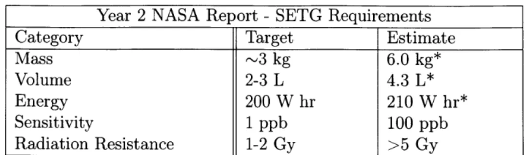
With that in mind, a stationary rover could theoretically provide 200 W hr to an instrument. Surviving the Martian transit trip means surviving the radiation environment of space, which was measured by MSL to be about 500 microGray per day [26]. Including operational time on Mars, 1 Gy radiation tolerance is a reasonable requirement. For sensitivity, the requirement to detect extent life in a regolith sample leads to the 1 ppb sensitivity requirement, established such that a theoretical SETG instrument could produce 1 Mb of data at a noise budget roughly equivalent to the one for reduced carbon detec-tion on Curiosity's SAM instrument [271. These requirements are displayed below:Year 2 NASA Report - SETG Requirements
Category Target Estimate
Mass ~3 kg 6.0 kg*
Volume 2-3 L 4.3 L*
Energy 200 W hr 210 W hr*
Sensitivity 1 ppb 100 ppb
Radiation Resistance 1-2 Gy >5 Gy
Table 2.1: SETG Requirements reported on Year 2 of the NASA report. Note that the mass, volume, energy draw, and sensitivity of the SETG instrument are currently higher than our target, while data return values are within budget
2.4
Subsystems
In order to fulfill these technical requirements, preliminary designs for each individual subsystem and for the overall system must be established.
2.4.1
Inlet
The inlet is, at the current stage, an under-explored aspect of the SETG instrument. While inlets on other systems such as the Phoenix lander can be used for inspiration, our workflow presents unique challenges. One of the challenges of the inlet is that it must be able to seal against the atmosphere to prevent the evaporation of reagents being introduced to the regolith. At the same time, the inlet has to open to accept regolith, without exposing liquids to the atmosphere. This necessitates some sort of airlock system, which has multiple points where sample can become clogged. In addition, the sample might have to be moved to other chambers where lysis and other steps can occur, either via a pump or pressure driven system, which is challenging if the sample is located in a reservoir that must unseal and then reseal. Additionally, the inlet is the first part of SETG that would interact with the regolith sample, and thus will depend heavily on the ability of a rover to introduce that sample to the SETG system. An assumption we are working under currently is that a ground, powderized sample can be introduced to the instrument via some sort of robotic arm, as is the case on MSL.
members of the SETG group have looked at potential designs, including a rotational inlet and an inlet that consisted of a sealing screw. For the budgets, a simple rotational acrylic airlock operated by a servomotor, inspired by the Phoenix lander's inlet, was envisioned, with rough values of 70 cubic centimeters (cc) and 150 grams for volume and mass. Energy draw was estimated as what was required to turn the servomotor and seal the inlet.
2.4.2
Sample Preparation
The sample preparation portion of the instrument is one of the more developed systems, due in part to our laboratory's partnership with Claremont BioSolutions (CBIO). CBIO actively develops and sells a system called PureLyse that performs mechanical lysis of cells through the spinning of micron-scale beads in a motor [23]. To gauge the performance of this subsystem, we use B. subtilis ATCC 6633 spores as a model for a tough-to-lyse extant organism. Based off of a 4 megabase genome, with one genome per spore, 1 ppb sensitivity translates to 10000 spores in a 50 mg sample. In order to produce 1 Mb of data with single molecule sequencing, we re-quire 2 picograms of DNA, which would rere-quire us to extract >5% of the DNA from
104 spores 127]. This assumes a 0.06 percent yield through library preparation and sequencing, which we are still working on achieving.
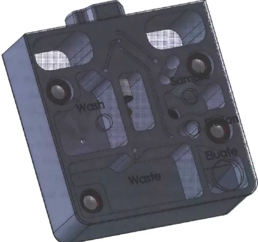
This system has been a major focus of technology development in our laboratory with the goal of attaining >5% DNA yield from a variety of Martian regoliths doped with B. subtilis spores. In addition, we are working with CBIO to develop solutions that would integrate all the pipetting steps in one automated cartridge. The PureLyse cartridge that was prototyped for us was based on the SimplePrep instrument, which was used to meet our TRL4 milestone. The prototype cartridge used a motor to drive a switching valve and evolved gas pumps to push fluid into a reservoir that would contain the OmniLyse motor (Figure 2-1). This cartridge was a one-time use device that would run the standard PureLyse protocol. Over the last two years, however, new protocols have been developed in our laboratory in an effort to create a "universal protocol" that can address the challenges of extracting DNA from regolith
that may contain salts, acids, or other disadvantageous chemical compounds 1281. The next cartridge design is in progress and should hopefully implement some of these new protocols. The volume and mass budgets were calculated based on the CAD diagrams for the prototype cartridge. Power and energy budgets were calculated to account for running the PureLyse motor and actuating the valves and pumps.
Figure 2-1: Prototype Sample Preparation Cartridge
2.4.3
Library Preparation
Library preparation is a key step that prepares DNA for sequencing. While there are many variances in library preparation that are dependent on the technology being used, traditionally it involves the fragmentation of DNA to the proper length, end repair of the strands to remove overhangs, ligation of adapters added to the ends of
the strands, and amplification of regions of the molecules to increase the amount of DNA available for sensing and sequencing. In using sequencing for space applications, several changes and considerations are introduced, however. First, amplifying nucleic acids may amplify contaminant DNA as well and might introduce bias. Library preparation is also technology specific, and can vary based on the sequencer being implemented in a final system.
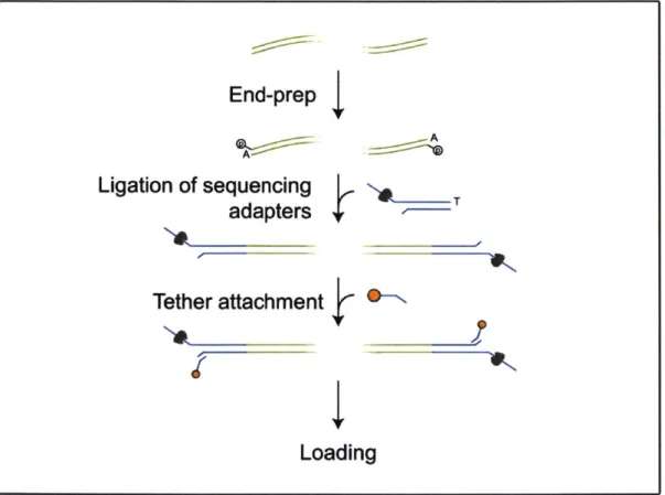
Library preparation for the MinION sequencer involves first taking DNA from the extraction subsystem and cleaning and purifying the sample. Then, since many double stranded DNA fragments will have single stranded overhangs after being sheared, these fragments have their tails enzymatically removed. A single nucleotide base, adenine, is added to both ends of the DNA strand. After further cleaning, motor proteins are added to the end of each fragment; these motor proteins ratchet the strand through the pores of the sequencer base-by-base. The sample is then ready for loading into the MinION (Figure 2-2).
Most library preparation protocols, and in particular the ones that are being used with the MinION sequencer, involve the transfer and heating of the fluid sample and reagents. As such, for the volume, mass, power, and energy budgets, a similar system to the sample preparation cartridge was envisioned and used for a rough approximation. As our library preparation protocols have changed, however, these budgets might need to be revised. New protocols are developed to be more efficient or meet different needs, and the MinION's protocols have undergone several changes through our time working with it. For example. the current library preparation protocol involves successive cleaning steps that could necessitate a change in design, depending on the results of the testing discussed later in the thesis.
2.4.4
Sequencing
A key components of the current SETG instrument is the MinION nanopore se-quencer. The system functions by utilizing a polymer membrane perforated by protein nanopores. A current is passed through each nanopore that changes as a nucleic acid passes through. That disruption in current can be used to characterize the nucleic
End-prep
Ligation of sequencing
Tadapters
Tether attachment
Loading
Figure 2-2: Diagram of Library Preparation Protocol for Ligation, adapted from Oxford Nanopore Technologies
acid, thus allowing for the sensing and identification of the molecule and the sequence of bases that it is comprised of. While there are other single molecule sequencers, the MinION is attractive due to its low mass, volume, and power requirements, as well as its space heritage from being run on the International Space Station [27]. The MinION is structurally composed of the sequencer itself as well as a FlowCell. The FlowCell contains the polymer membrane and fluidic channels, while the sequencer contains the electronic components to complement the FlowCell. The MinION is small both in mass and volume, estimated at 87 grams and 80 cc, with only a 1 Watt power requirement. A standard sequencing run, however, can take time, and results in a large energy draw: a 48 hour run would use 48 Watt-hours. Addition-ally, the sequencer is designed to function at room temperature, and will control the temperature of the internal sequencing reactions based off of that assumption.
2.4.5
Data Processing
Data processing from the MinION involves recording the ionic currents from the system, and relies on the MinKNOW software package, which runs and saves the sequencing data from the MinION. These saved files are then run through a basecaller, a program that interprets the signals and assigns bases to a read signal based on its probability. Traditionally, MinKNOW is run on a computer connected to the MinION, while basecalling might be done either on the cloud or on a powerful local machine. Typical runs from the MinION can produce data volumes on the order of hundreds of gigabytes after basecalling; however, shorter runs can be performed to produce smaller datasets.
Initial designs for the SETG instrument envision a flexible programmable gate array (FPGA) that would process read signals, which would then be stored for later engineering analysis. The instrument would likely store raw signals on a limited basis, in addition to processed bioinformatics data such as histograms and quality scores. Storage is necessary, due to the modest data return rate from Mars of 1 Gb/day
[23].
The budgets for the data processing system were based off of a nominal system on a circuit board, like the Xilinx Kintex-7
[231.
While significant volume and mass margin was provided for the computing system to grow, the instrument should hopefully not exceed these values. The power draw of the data processing subsystem is likely to be substantial, and that is reflected in the power budget.2.4.6
Waste Management
Waste management is included in the original budgets as a necessary aspect of the instrument. Reagents cannot just be vented to the Martian surface, due to contam-ination control concerns. Storage of those reagents is also important, since many of them could lose their efficacy upon freezing or even potentially damage tubing and structures. Despite the importance of this process, the waste subsystem was not a pri-mary focus so far in development. Many other aspects of the SETG instrument, such as the Sample Preparation subsystem, already have some amount of space defined
for waste reagents. The final design of the subsystem could be simple and involve an unheated chamber that would seal and allow internal reagents to freeze, or it could include a more complicated method involving some sort of absorptive material like a foam. Additionally, the design of this component is intimately related to the number of runs the instrument has planned; if very few runs are planned other subsystems such as Sample and Library Prep could have their own waste sections. If many runs are expected, a more dedicated waste subsystem would be required.
For the budget, a small, simple chamber for reagent storage was envisioned and planned for in terms of mass and volume. This system would likely draw very little power or energy, especially if it used vacuum to drive fluid to its chamber.
2.4.7
Power Conditioning and Thermal Control
The current SETG instrument is being designed to function off of a 24V bus, such as the one on the Mars Science Laboratory. The power draw of certain systems, such as the MinION, is well defined, while some components, such as the data processing subsystem, have a range of potential values. The pump actuation required for fluid movement could use evolved gas generators that would require very low currents, and the valves required for flow direction could take advantage of vacuum actuation to minimize power. Continued testing and iteration is required to gain a more substantial handle on the power requirements of many subsystems.
Heating could potentially be a major components of those requirements. From an estimated Martian temperature of -55' C, the system would require a large amount of power to bring all its components up to operating specification; heating just the sequencer and sample prep cartridge to operating temperature is estimated to require 4 Watt-hours, based on a typical survival heater Watt density. Maintaining the temperature band required for sequencing is another question, involving the interplay of power draw from components and heat losses through the vessel. To that end, we are developing a thermal model to help manage the system's heating and cooling.
The volume and mass of heating elements was not considered a large factor, with insulation and resistive heaters both being low mass temperature control options. The
power and energy draw, however, is large, as previously discussed. Over time, how-ever, as our thermal model improves, we expect us to fall well under budget for power and energy, potentially at the expensive of mass growth for passive heating/cooling elements.
2.4.8
Structure
The structural form of the SETG instrument was ill defined at the initial design stage. We opted for a strong, wear-resistant, easily machinable material for the outer structure: aluminum, commonly used on many other space instruments
1291.
Aluminum's conductive properties can be balanced with insulation internally to assist in thermal control. The structural mass and volume budget were estimated based on the total volume of the other components of the system; the volume of each other subsystem was calculated with wiring and air considerations in place, so a cube that would be allow for all the components to be housed inside was used as a first estimate. The mass of the structure was then established from the volume of the box and the density of aluminum. Structure is a subsystem, however, that can be redesigned and likely will be as the other scientific subsystems of the SETG instrument grow or shrink in volume and mass. As such, it was provided plenty of margin during design.2.5
Mass, Volume, and Energy Budgets
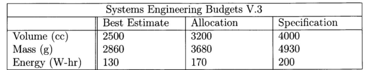
These design considerations lead to the creation of budgets for mass, volume, and energy for the instrument. The nominal system at the time of the creation of these budgets was one that would process four samples with two sequencers for redundancy. The initial budgets are presented in the table below (Table 1):
A current best estimate for mass, volume, and energy draw was established for each subsystem. From there, we allocated extra margin to each subsystem based off of our expectations for how the system might grow. Then, after summing all of the subsystems together, a total system margin was added to create our specification, providing our budgets with a lower and upper bound.
Systems Engineering Budgets V.3
Best Estimate Allocation Specification
Volume (cc) 2500 3200 4000
Mass (g) 2860 3680 4930
Energy (W-hr) 130 170 200
Table 2.2: Current Budgets for SETG System
2.6
Discussion
The initial budgets for volume and mass fall within the expectation for a rover based Mars instrument. The energy draw of the system was high, at 130 Watt-hours. Much of this power can be attributed to sequencing and computation, however, and typically power estimates tend to decrease over the course of a system's design due to better understanding of the thermal requirements [30]. Developing these budgets involved diving into the individual subsystems of the SETG instrument and how they functioned. Continued work has been done to describe the details of these subsystems more accurately, but the budgets are still valid ways to look at the instrument from a requirements perspective. Additionally, they help direct the testing effort in the lab to attain more accurate values for these budgets as well as prototypes for key subsystems. The TRL5 and TRL6 efforts are directly informed by the initial design steps taken during this phase of development.
Chapter 3
TRL5 Development
3.1
SETG Automation
The data presented in the preliminary SETG budgets are informative for making future decisions on system design. In order to move forward with technology de-velopment, however, it is necessary to verify whether these budgets are reasonable. In addition, it is necessary to be able to automate the SETG process; manual han-dling is common to many protocols, and existing liquid hanhan-dling systems are not spaceflight-ready. These two fundamental ideas drove the creation of the Automated SETG Testbed, a system designed to automate the SETG process from sample to sequence. Testing and verifying the subsystems of the SETG instrument will help us evaluate if our original budgets were reasonable or if some components need to be redesigned. In addition, in developing the system for repeatability, we can show the sensitivity of sequencing results to subsystem inputs, which will provide information for the development of more effective protocols in terms of power, energy, and timing.
3.1.1
Overview
The SETG testbed functionally has three main subsystems: extraction, library prepa-ration, and loading/sequencing. The extraction subsystem receives, as an input, an environmental sample and produces, as an output, eluate of concentrated DNA. That
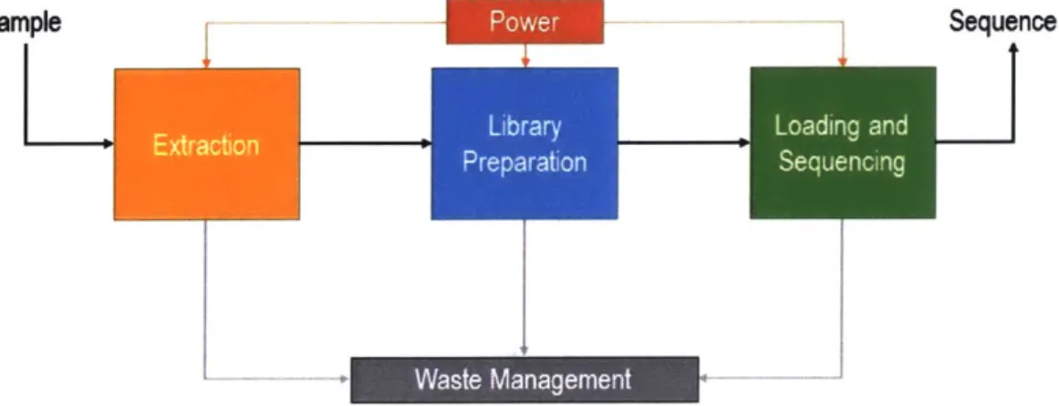
output is the input to the library preparation subsystem, which produces ready-to-sequence DNA. The loading/sequencing subsystem then takes the ready-to-ready-to-sequence DNA and produces sequencing data (Figure 3-1). Other previously discussed sub-systems, such as power, thermal, structure, and waste management, serve to support these three main functional subsystems. This outlook does not necessarily reflect the specific hardware layout of the system, but is an organized way to test and evaluate important subsets of the overall testbed (Figure A-1).
Sample Sequence
-- Waste Management
Figure 3-1: Automated SETG Testbed Block Diagram. Power and Waste Manage-ment are shown as additional subsystems. Structure and Data Processing are not, and are less relevant at this stage of testing.
3.1.2
Current Best Solution
To the best of our knowledge, a full sample-to-sequence automated system does not exist. Thus, in order to evaluate the performance of our test bed, we need to compare the performance of each of the three main subsystems to the current solutions.
Extraction
The current solution we are exploring is extraction of DNA from spores via the PureLyse system, described in the previous chapter. This method, a mechanical lysis method rather than a chemical or enzymatic lysis method, is considered to be our current best extraction solution. Our team has published several results from this
system in terms of percent yield, i.e. mass of DNA extracted divided by percent of mass of DNA added in [28]. The current protocol is a custom designed SETG protocol, meant to be agnostic to the choice of Martian regolith.
Library Preparation
Oxford Nanopore has several library preparation protocols designed specifically for the MinION flow cell, all designed to be done by hand. These protocols have different purposes, based on what device we would be using, how long we expect our strands to be, whether we can use polymerase chain reaction (PCR), and so on. With benchtop experimentation, we found that a modified version of Oxford's 1D Genomic DNA Ligation would be ideal. The protocol is called the One Pot Ligation Protocol, and was designed by Josh Quick of the University of Birmingham; we found it attractive due to its low number of bead cleanups and that it delivered high yields with a minimal number of steps [31]. We have quantified yield efficiency on the bench very well, though the only way to test if the library was successfully adapted for the MinION is to attempt to sequence it. The current best solution is still a human researcher or robotic arm moving reagents via a pipette.
Sequencing
The current solution for sequencing involves loading the MinION sequencer by pipette, before connecting it to a computer and running the MinKNOW program for anywhere from 1 to 48 hours. Successful loading of the MinION is determined by whether any leakage occurred from the Flow Cell and whether the MinION sequences the DNA we expect to find. While leakage is a catastrophic form of failure, and a large amount of data could be lost by inducing leaks during loading, the amount of data produced by the MinION also depends on other factors, such as flow cell quality. Regardless, if the MinION can sequence the nucleic acids that have been loaded, that is a good sign that library preparation was at least partly successful. A full success from sequencing would involve the MinION reporting a large number of reads within 24 hours, within an order of magnitude of the number of reads reported for a manual library.
3.2
Components and Methods
It is clear that an automated SETG system would improve upon our current solution and would move us towards TRL6 and subsequently a flight prototype. The following sections expand upon how that automated testbed was designed and created, first starting with the protocols requirements set by SETG and selecting hardware and software to meet those needs.
3.2.1
Work-flow
The section that follows is a heavily abridged version of the current protocols for extraction, library preparation, and sequencing, in order to understand the motivation for the testbed hardware. These protocols may not reflect what is currently being done on the bench, but rather the procedures being developed for automation.
Extraction
1. The input sample (regolith or water) is desalting and suspended in buffer, along with competitive binders.
2. The slurry is pushed back and forth through an OmniLyse device as it runs, lysing any spores in the slurry.
3. Buffer is pushed through the OmniLyse device to wash the system. 4. Elution buffer is delivered to the OmniLyse and heated.
5. The elution buffer is pushed through the device to the next subsystem.
Library Preparation
The library preparation subsystem can then be subdivided into three sub-subsystems. 1. First Bead Cleanup
(b) A magnet is moved such that it holds the beads in place on the inside of the reservoir.
(c) Elution buffer is removed and the chamber is washed with ethanol twice. (d) The magnet is moved away. Elution buffer is added to the bead solution
and heated.
(e) The magnet is moved back. The beads are pulled back to the wall. (f) The water is pushed along as eluate.
2. End Prep and Ligation
(a) End preparation buffer and enzymes are added to the eluate, to prepare the ends of the nucleic acid strands.
(b) Ligation master mix, ligation enhancer, and nucleic acid adapters are added to the solution and allowed to incubate.
3. Second Bead Cleanup
(a) The solution is introduced to another reservoir of Ampure XP solution. (b) The steps of the first bead cleanup are repeated with different buffers, to
clean the library after the previous End Prep and Ligation step. (c) The elution buffer is pushed to the next subsystem.
Sequencing
1. The priming buffer is loaded into the MinION.
2. The elution buffer, mixed with other buffers to become the library, is loaded into the MinION
3.2.2
Hardware
Testing the automation of the subsystems was the most important factor in the testbed's design. While the final SETG instrument may be a custom designed, inte-grated device, that would not be conducive to modifying protocols and shifting design requirements. Since the automated testbed is meant to inform the final design, we were interested in selecting components that were modular and could be easily con-trolled via software, while still being able to drive small amounts of fluid precisely. LabSmith is a company that produces reservoirs, tubing, valves, pumps, sensors, and other fluid handling components for micro-fluidic applications, all made with inert components and designed to minimize dead volumes. LabSmith components a large majority of the current testbed. Additionally, a custom-built solenoid bay combined with a pump is used to generate pressure to move fluids from one container to an-other. The control computer powers LabSmith components, while two power supplies provide power to the non-LabSmith components. Unique components were also used for each individual subsystem.
Extraction
The Omnilyse device is a major part of the extraction subsystem, and is integrated via adapters to the 1/16" outer diameter (OD) tubing used throughout the subsystem. A PhD Ultra syringe pump is currently used for the lysis portion of the testbed; since it actuates a BD 3 ml syringe, it simulates the traditional PureLyse protocol more accurately than a pump with its own reservoir. An 8-way flow selection valve is also used centrally in the subsystem.
Library Preparation
In addition to previously discussed components, two magnetic assemblies were created by attaching neodymium permanent magnets to the shafts of two brushed small motors. The motors can be spun by a motor controller to move the magnets away from and up against the wall of a reservoir, in order to actuate paramagnetic
beads used in each protocol. Bio-Chem Fluidics one way valves prevent backflow, while resistive heaters raise the temperature of reagents for reactions.
Sequencing
The Oxford Nanopore sequencer is naturally implemented in this subsystem. Ad-ditionally, we built a custom-designed fluidic interface, designed by Kendall Saboda, that connects LabSmith tubing to the MinION Flow Cell's ports for automatic load-ing. Additional components include a bubble trap, a Sensirion flow meter, and Bio-Chem one way valves.
3.2.3
Software
The testbed is designed to be controlled via a computer running MathWorks Simulink, communicating with components through serial ports or a National Instruments data acquisition board (DAQ). Simulink provides for unified control for many different components from different vendors, and allows for the precise timing and repeatability required for automated SETG protocols. In addition, the block-based programming approach lends itself to code modularity alongside component modularity, and allows for open-loop or closed-loop control further along development.
3.3
Design
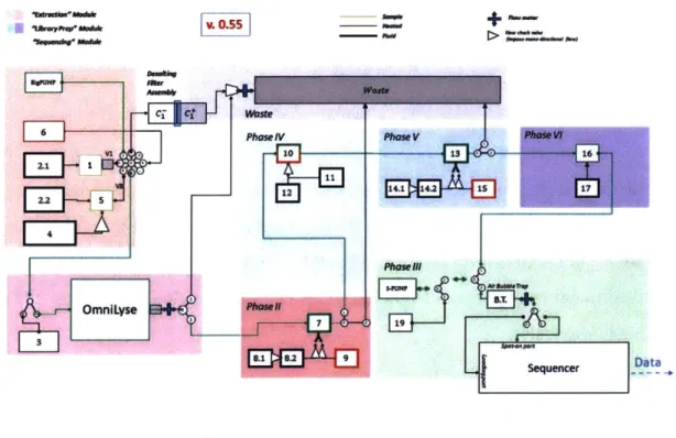
To design the testbed and plan for its construction, Dr. Jacopo Tani created sev-eral flowcharts to establish the automated versions of the SETG protocols. These flowcharts describe the processes that a nominal instrument would take from sample to sequence, and were living documents that morphed as our design shifted through construction. The current version of the flowchart is split into phases, where each phase is a step in the instrument process. Phases 1 and 2 are sample preparation phases, while Phases 3 through 7 are library preparation phases (Figure 3-2).
MO .1,1111W MR" ft-MV CT Ct Waste =IV phase VI 10 12 OmnlLyse 7 8.1 8.2 9
+
a Vast. Phase V Phase Vi 136 Phasernt ~Ij.. 4*W;7vf
Sequencer -DataFigure 3-2: Automated SETG Testbed Flowchart. Each numbered box is a reservoir within the system.
Physical Layout
The physical layout of the automated testbed is not required to follow its functional layout. The phases of the system provide a rough framework for the layout, but the testbed footprint can be reduced if need be. Additionally, large components such as power supplies have to be located such that they can be accessed by several different components. The layouts of each subsystem as of writing the thesis are described below.
3.3.1
Extraction
Extraction on the lab bench consists of the OmniLyse device, tubes of reagents, and actuation via syringe. As such, the automated extraction subsystem primarily consists of the OmniLyse device, reservoirs of reagents, and actuation via the PHD Ultra Syringe Pump (Figure 3-3). The automated extraction protocol is designed to emulate the bench protocol, discussed in the previous section, with several key
differences. The Bio-Chem Fluidics 8-way valve is used such that the syringe pump can interface with multiple reservoirs. 3-way valves allow for pushing used reagents to waste. Desalting is not implemented via a centrifugal method, but rather through pushing fluid through a 0.2um filter; this is effectively desalting since cells are typically bigger than 0.2um and free DNA will be bound to sediment, while salt ions would pass through. While this is effective and can be implemented into our testbed, it is worth noting that this is not a true desalting approach, since salt ions are far smaller than the filter cutoff size. The input to this subsystem is the environmental sample of spores, while the output is an eluate of extracted DNA.
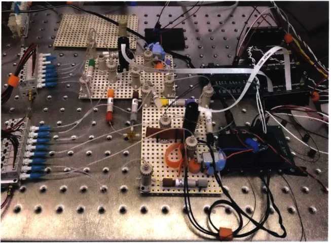
Figure 3-3: Extraction Subsystem. The subsystem has been spread over a large area
to facilitate easy access and modification.
3.3.2
Library Preparation
The Library Preparation subsystem has the largest number of components, since the library preparation protocol contains a larger number of reagents and steps than
A-extraction or sequencing. Primarily, the library preparation subsystem consists of more than 20 reservoirs, with the pressure generator moving reagents and sample from one reservoir to the next (Figure 3-4). The small liquid volumes used in library preparation necessitate thinner tubing and greater control over dead volumes. The heating elements are used to heat several reagents for reactions. 3-way valves are used to divert fluid to waste while the magnet assemblies (made up of a motor and a physical magnet) can hold or release the ferromagnetic Ampure XP bead solution, discussed in previous chapters. The input to the subsystem is the extracted DNA eluate from the extraction subsystem. The output is cleaned and prepped DNA to be loaded into the MinION Flow Cell.
Figure 3-4: Library preparation subsystem
3.3.3
Sequencing
The sequencing subsystem is mainly comprised of two parts: the loading apparatus and the MinION sequencer. The loading apparatus consists of the previously dis-cussed custom-made acrylic interface with connectors that mate with tubing from the rest of the automated testbed (Figure 3-5). This interface has four ports that correspond to the four ports of the MinION Flow Cell: the Loading Port, the Spot On Port, and the two Waste Ports. A precise 80 ul LabSmith automated syringe pump is used to deliver the sample into the MinION, since loading involves delivering small volumes of fluid with precise timing, without disturbing or damaging the flow cell's nanopore membrane. The sequencer itself is a standard MinION sequencer, with holes drilled in the lid to allow the loading interface to access the flow cell. Additionally, a 3D printed clip compresses the interface against the flow cell. The air bubble trap prevents bubbles from forming and interfering with MinION loading, while the flow meter monitors the fluid volumes inserted into the flow cell. The completed library is the input to this system, and the output is sequence data.
3.3.4
Additional Subsystems
In order to serve these three main subsystems, other subsystems were designed as well, described below.
Data Processing
The MinION sequencer is operated via a connection to a computer running Min-KNOW. For the testbed implementation, a separate computer is used for the MinION so that the testbed computer can focus on automation. Data acquisition and base calling are all handled by that local computer. For the testbed, we used the UDOO X86, a single board, quad core, x86 architecture computer. This board is notable both for its use of Intel architecture, making it MinKNOW compatible, as well as its small footprint; at 102 square cm, it is a viable computer for a future flight prototype.
S@
*
0e
00
-*
r:66: **Figure 3-5: Sequencing subsystem, focused on the acrylic loading interface. Power Conditioning and Thermal Control
The automated testbed is not operating off of the same constraints as the final in-strument; there is no singular 24 V bus powering the entire system. All components, however, are powered with less than 12 V from one of two power supplies. Using power supplies set at different levels accurately simulates multiple power rails on a bus, while allowing for rapid changes in voltages during subsystem testing.
Structure
There is no structural housing to the current automated testbed. The system is developed on the lab bench and is allowed to take a larger surface area than the final instrument would require. This allows for modularity and ease of assembly to the testbed; however, as the system is tested and optimized, the volume of the testbed can be reduced. These results will allow the final device to occupy a much smaller
footprint.
Waste Management
The waste generated by a run of the testbed is designed to be stored in separate waste reservoirs. Additionally, a container that has been emptied of its contents can be used to store waste as well. This policy works well with the cleaning protocol established for the testbed. No physical component, outside of the BD 3 ml syringe and OmniLyse device, is disposable; every component has to be cleaned between test runs. Thus, after a test run, waste containers are manually emptied and the full system is flushed with sporicide. After emptying the reservoirs again, the system is flushed with pure water and emptied twice. The sporicide eliminates organics inside the system and the water flushes out the sporicide. This allows for simple waste management while eliminating contaminants from run to run.
3.4
Testing and Results
3.4.1
Extraction
The sample preparation step has been the primary focus of the initial stages of testing. Due to ongoing work done by our laboratory and our partners Claremont BioSolu-tions, we have an extensive data set for extractions in a bench-top environment [281. Thus, we can compare the yield efficiency of automated extraction with manual ex-traction. The majority of testing was conducted with an aliquot of roughly 108 B.
subtilis spores in water.
Initial testing built up to extraction slowly. First, long fragments of DNA, ex-tracted from E. coli, sheared to 6 kilobases and suspended in pure water, were pushed through the OmniLyse device while it was running, using no additional buffers. This was to test where we were liable to lose sample in the system, as well as compare val-ues to manual lysis. Afterwards, the same was done with B. subtilis spores. Finally, full extraction was done with B. subtilis spores.
Initial lysis testing resulted in low yields, which led to new design iterations that included reducing tubing length and removing components that were potential sources of sample loss, such as the flow meter. The testing protocol was also modified to allow for larger elution volumes and heated elutions. Minor changes in layout were also made after testing, such as tilting the OmniLyse device to ensure that it fills before lysing. The modularity of the system made these changes easier to implement after realizing that the protocol had to be modified.
While these tests resulted in better yields, the greatest jump in functionality was in implementing a pre-treatment step in extraction. I theorized that with the extensive tubing length of our system, it was possible that DNA from the lysed spores was binding to the inside of our tubing, leading to significant sample loss. As such, I introduced a pre-treatment step where I flush the extraction system with sodium pyrophosphate.
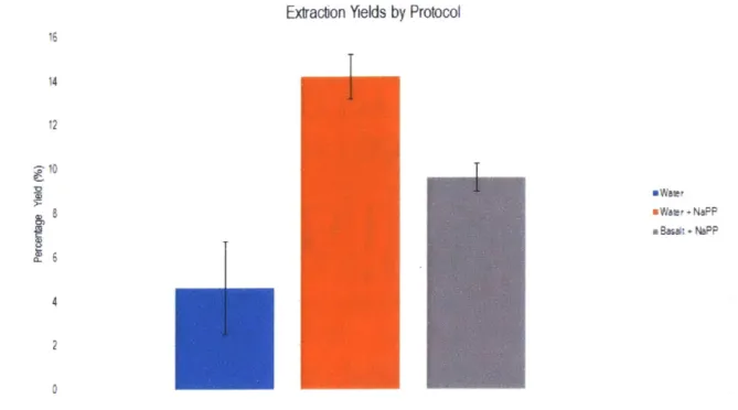
Sodium pyrophosphate (NaPP) is known to inhibit binding of nucleic acids to surfaces; the molecules occupy the same charge sites that DNA would, reducing the number of sites that DNA could bind to while traveling through tubes. By flushing the system with NaPP prior to extraction, we would allow many of the binding sites inside the tubing of the system to be bound to NaPP molecules, allowing more DNA to pass through to the final elution. After implementing this step, I saw our yields increase. With spores in water, I was able to attain yields on par with manual extractions (Figure 3-6). Initial tests with basalt were also promising, potentially leading to developments that could allow the automated system to surpass manual handling. Unfortunately, the introduction of regolith began to damage one of the valves in the 8-way BioChem valve, rendering that port inoperable. Automated regolith testing has been paused until a better fluid selection system has been designed or purchased. We plan for future systems to avoid moving regolith as much as possible. Additionally, an in-situ SETG instrument would process a limited number of samples, minimizing the potential for valve damage. For now, future integration testing will continue to use water, as this does not damage the flow selection valves in the testbed.
Extraction Yields by Protocol
I
a Bas* + No-P: 4 2 0Figure 3-6: Extraction Yields with Water, before and after using NaPP as a pre-wash. Basalt data is included to compare with water. Water extractions and basalt extractions with NaPP match manual extraction yield numbers.
to automated extractions, providing a path to the next version of SETG, there is additional work to be done. Desalting has not been implemented into the system, since neither water nor basalt regolith need desalting for extraction. Additionally, manual research suggests that heating the OmniLyse device during elution is better than delivering a heated elution buffer; that has yet to be implemented, as well. Looking ahead, the current testbed could have future issues with clogging, since it cannot dynamically account for clogs in the system. While manual handling allows for simple dynamic pressure and speed adjustment based on visual and tactile data, the testbed would have to evolve and implement several more sensors and a more sophisticated feedback control loop to achieve the same result. For now, however, the subsystem has successfully demonstrated spore extraction from water and basalt, with sufficient yields to meet system requirements.
16 14 12 -10 CD